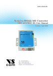
1
Vorne Industries
87/003
87 Handheld Terminal
User's Manual
1445 Industrial Drive
• Itasca, IL 60143-1849
• (630) 875-3600
• Telefax (630) 875-3609
. 3
Chapter 1 Setting Up Your Display For Operation . . . . . . . . . . . . . . . . . . . . . . . . . . .
1.1 Operation . . . . . . . . . . . . . . . . . . . . . . . . . . . . . . . . . . . . . . . . . . . . . . . . . . . . . . . . . . . . . . . . . . 3
1.2 Wiring . . . . . . . . . . . . . . . . . . . . . . . . . . . . . . . . . . . . . . . . . . . . . . . . . . . . . . . . . . . . . . . . . . . . . . 3
1.3 RS-232 Communication To A Single 87/232, 87/708, 87/712 or 87/719 Display . 4
Selecting RS-232 Communication on an 87/232 Series Display. . . . . . . . . . . . . . . . . . . . . . . . . 4
Wiring Diagram For RS-232 Communications from an 87 Terminal To One Display . . . . . 4
1.4 RS-232 Communication To A Single 87/256, 87/415, 87/705 or 87/805 Display . 4
Wiring Diagram For RS-232 Communication From An 87 Terminal To One Display . . . . . 4
1.5 Guidelines For Wiring RS-232 Devices . . . . . . . . . . . . . . . . . . . . . . . . . . . . . . . . . . . . . . 5
1.6 RS-422 Or RS-485 Communication To One Or More 87/232 Displays . . . . . . . . . 5
Selecting RS-422/RS-485 Communication . . . . . . . . . . . . . . . . . . . . . . . . . . . . . . . . . . . . . . . . . . . . . 5
Wiring Diagram For RS-422 Or RS-485 Communication From An 87 Terminal To One . 5
Display . . . . . . . . . . . . . . . . . . . . . . . . . . . . . . . . . . . . . . . . . . . . . . . . . . . . . . . . . . . . . . . . . . . . . . . . . . .
Wiring Diagram For RS-422 Or RS-485 Communication From An 87 Terminal To More . 6
Than One 87/232 Display . . . . . . . . . . . . . . . . . . . . . . . . . . . . . . . . . . . . . . . . . . . . . . . . . . . . . . . . .
1.7 RS-422 Or RS-485 Communication To One Or More 87/256 Displays . . . . . . . . . 7
Selecting RS-422/RS-485 Communication . . . . . . . . . . . . . . . . . . . . . . . . . . . . . . . . . . . . . . . . . . . . . 7
Wiring Diagram For RS-422 Or RS-485 Communication From An 87 Terminal To One . 7
Display . . . . . . . . . . . . . . . . . . . . . . . . . . . . . . . . . . . . . . . . . . . . . . . . . . . . . . . . . . . . . . . . . . . . . . . . . . .
Wiring Diagram For RS-422 Or RS-485 Communication From An 87 Terminal To More . 8
Than One 87/256 Display . . . . . . . . . . . . . . . . . . . . . . . . . . . . . . . . . . . . . . . . . . . . . . . . . . . . . . . . .
1.8 Guidelines For Wiring RS-422 Or RS-485 Devices . . . . . . . . . . . . . . . . . . . . . . . . . . . . 9
1.9 Addressing Multiple Displays . . . . . . . . . . . . . . . . . . . . . . . . . . . . . . . . . . . . . . . . . . . . . . . . 9
Unit Address . . . . . . . . . . . . . . . . . . . . . . . . . . . . . . . . . . . . . . . . . . . . . . . . . . . . . . . . . . . . . . . . . . . . . . . . . . . 9
1.10 Relay Output . . . . . . . . . . . . . . . . . . . . . . . . . . . . . . . . . . . . . . . . . . . . . . . . . . . . . . . . . . . . . 10
Relay Connectors . . . . . . . . . . . . . . . . . . . . . . . . . . . . . . . . . . . . . . . . . . . . . . . . . . . . . . . . . . . . . . . . . . . . . 10
Activate Relay . . . . . . . . . . . . . . . . . . . . . . . . . . . . . . . . . . . . . . . . . . . . . . . . . . . . . . . . . . . . . . . . . . . . . . . . 10
Chapter 2 Communicating With The 87 Terminal . . . . . . . . . . . . . . . . . . . . . . . . . . . .
11
2.1 Establishing a connection between an 87 Terminal and an 87 Display . . . . . . . 11
2.2 Viewing User Setup Parameters . . . . . . . . . . . . . . . . . . . . . . . . . . . . . . . . . . . . . . . . . . . . 11
Display Value . . . . . . . . . . . . . . . . . . . . . . . . . . . . . . . . . . . . . . . . . . . . . . . . . . . . . . . . . . . . . . . . . . . . . . . . . 12
Preset One And Preset Two . . . . . . . . . . . . . . . . . . . . . . . . . . . . . . . . . . . . . . . . . . . . . . . . . . . . . . . . . . 12
Initial Value . . . . . . . . . . . . . . . . . . . . . . . . . . . . . . . . . . . . . . . . . . . . . . . . . . . . . . . . . . . . . . . . . . . . . . . . . . . 12
Input 1 Factor And Input 2 Factor . . . . . . . . . . . . . . . . . . . . . . . . . . . . . . . . . . . . . . . . . . . . . . . . . . . . . 13
Pacing Time . . . . . . . . . . . . . . . . . . . . . . . . . . . . . . . . . . . . . . . . . . . . . . . . . . . . . . . . . . . . . . . . . . . . . . . . . . 13
2.3 Changing User Setup Parameters . . . . . . . . . . . . . . . . . . . . . . . . . . . . . . . . . . . . . . . . . . 13
87/003 Terminal Users Manual
1
Numeric keys 1 thru 9 and 0 . . . . . . . . . . . . . . . . . . . . . . . . . . . . . . . . . . . . . . . . . . . . . . . . . . . . . . . . . . 13
Escape . . . . . . . . . . . . . . . . . . . . . . . . . . . . . . . . . . . . . . . . . . . . . . . . . . . . . . . . . . . . . . . . . . . . . . . . . . . . . . .
13
Delete . . . . . . . . . . . . . . . . . . . . . . . . . . . . . . . . . . . . . . . . . . . . . . . . . . . . . . . . . . . . . . . . . . . . . . . . . . . . . . . .
13
Colon . . . . . . . . . . . . . . . . . . . . . . . . . . . . . . . . . . . . . . . . . . . . . . . . . . . . . . . . . . . . . . . . . . . . . . . . . . . . . . . .
13
Minus sign . . . . . . . . . . . . . . . . . . . . . . . . . . . . . . . . . . . . . . . . . . . . . . . . . . . . . . . . . . . . . . . . . . . . . . . . . . . .
13
Space . . . . . . . . . . . . . . . . . . . . . . . . . . . . . . . . . . . . . . . . . . . . . . . . . . . . . . . . . . . . . . . . . . . . . . . . . . . . . . . .
13
Decimal Point . . . . . . . . . . . . . . . . . . . . . . . . . . . . . . . . . . . . . . . . . . . . . . . . . . . . . . . . . . . . . . . . . . . . . . . . 14
Enter . . . . . . . . . . . . . . . . . . . . . . . . . . . . . . . . . . . . . . . . . . . . . . . . . . . . . . . . . . . . . . . . . . . . . . . . . . . . . . . . .
14
Function keys . . . . . . . . . . . . . . . . . . . . . . . . . . . . . . . . . . . . . . . . . . . . . . . . . . . . . . . . . . . . . . . . . . . . . . . . 14
Reset Display . . . . . . . . . . . . . . . . . . . . . . . . . . . . . . . . . . . . . . . . . . . . . . . . . . . . . . . . . . . . . . . . . . . . . . . . . 14
Log Out . . . . . . . . . . . . . . . . . . . . . . . . . . . . . . . . . . . . . . . . . . . . . . . . . . . . . . . . . . . . . . . . . . . . . . . . . . . . . .
15
Next Unit . . . . . . . . . . . . . . . . . . . . . . . . . . . . . . . . . . . . . . . . . . . . . . . . . . . . . . . . . . . . . . . . . . . . . . . . . . . . .
15
Password . . . . . . . . . . . . . . . . . . . . . . . . . . . . . . . . . . . . . . . . . . . . . . . . . . . . . . . . . . . . . . . . . . . . . . . . . . . . .
15
Unit ID . . . . . . . . . . . . . . . . . . . . . . . . . . . . . . . . . . . . . . . . . . . . . . . . . . . . . . . . . . . . . . . . . . . . . . . . . . . . . . .
15
2.4 Error Messages . . . . . . . . . . . . . . . . . . . . . . . . . . . . . . . . . . . . . . . . . . . . . . . . . . . . . . . . . . . . 16
UNIT NOT RESPONDING . . . . . . . . . . . . . . . . . . . . . . . . . . . . . . . . . . . . . . . . . . . . . . . . . . . . . . . . . . . . 16
Out of Range . . . . . . . . . . . . . . . . . . . . . . . . . . . . . . . . . . . . . . . . . . . . . . . . . . . . . . . . . . . . . . . . . . . . . . . . . 16
Function is: Not Programmed . . . . . . . . . . . . . . . . . . . . . . . . . . . . . . . . . . . . . . . . . . . . . . . . . . . . . . . . . 16
User Setup Parameter Not supported . . . . . . . . . . . . . . . . . . . . . . . . . . . . . . . . . . . . . . . . . . . . . . . . . 16
Communication errors . . . . . . . . . . . . . . . . . . . . . . . . . . . . . . . . . . . . . . . . . . . . . . . . . . . . . . . . . . . . . . . . 16
Appendix A Operating Specifications . . . . . . . . . . . . . . . . . . . . . . . . . . . . . . . . . . . . . . .
Appendix B Terminal Dimensions . . . . . . . . . . . . . . . . . . . . . . . . . . . . . . . . . . . . . . . . . .
17
18
Notice Of Disclaimer
While the information in this manual has been carefully reviewed for accuracy, Vorne
Industries, Inc. assumes no liability for any errors, or omissions in the information. Vorne
Industries also reserves the right to make changes without further notice to any products
described in this manual.
2
87/003 Terminal Users Manual
Chapter 1 Setting Up Your Display For Operation
This chapter describes how to set up the terminal hardware for operation with an 87 Series
Display, including connecting power, and wiring to the serial communication port.
1.1 Operation
The 87/003 Terminal is a handheld remote entry Terminal designed to interface with 87 Series
displays. The 87 Terminal can communicate with an 87 Display using either the RS232 or RS422
serial port. Two types of features can be remotely accessed by the 87 Terminal, Display
Parameters and Function key features. Display parameters consist of Display Value, Preset One,
Preset Two, Initial Value, Input 1 Factor, Input 2 Factor and Pacing Value. Function key features
consist of Jog Input One, Jog Input Two, Relay On, Relay Off and Flash Data. There are four
Function keys which can be programmed to use these features.
1.2 Wiring
The 87 Terminal receives power and serial data thru a male DB-9 connector located at the bottom
of the unit. The 87 Terminal can be powered by the 87 Series Displays 12VDC output.
Caution: Reversing the +12VDC and ground connections may damage the 87 Terminal.
87 Terminal DB-9 Connector Pinout
DB9 MALE
+12V DC In
RS232 In (RxD)
RS232 Out (TxD)
No Connection
Signal Ground
1
2
6
3
7
4
8
5
9
RS422 Out RS422 Out +
RS422 In RS422 In +
WARNING - SHOCK HAZARD
Always completely disconnect power from the display before
opening the user access plate. Do not reapply power to the
display until the access plate has been reinstalled and
securely closed.
87/003 Terminal Users Manual
3
1.3 RS-232 Communication To A Single 87/232, 87/708, 87/712 or 87/719 Display
This section provides the information necessary to successfully interface an 87 Terminals RS-232
port to one 87/232 display. 87/232, 87/708, 87/712, and 87/719 Displays share the same wiring.
Selecting RS-232 Communication on an 87/232 Series Display.
A printed circuit board mounted COM PORT slide switch, located beside the COM PORT
terminal strip, is used to select between RS-232 and RS-422/RS-485 communication. Set this
switch to the RS-232 position.
Wiring Diagram For RS-232 Communications from an 87 Terminal To One Display
The only connections necessary for two way communication between an 87 Terminal and an
87/232 display are the ones shown in the diagram below. Please refer to section 1.5 Guidelines For
Wiring RS-232 Devices for important wiring recommendations.
P2
Vorne Industries 87 Terminal
87 Counter
Unit 0
Display Value is:
12345678
1
+12V DC IN
2
Receive Data (RxD)
3
Transmit Data (TxD)
4
F1
F2
Escape
Reset
Display
F3
Log
Out
1
2
3
Display
Value
Preset
One
Preset
Two
4
5
6
Initial
Value
Input 1
Factor
Input 2
Factor
7
8
9
F4
Next
Unit
Delete
:
Pacing
Time
0
Space
.
Enter
87 Terminal
5
Signal GROUND
12V DC
0V DC
RS232 Transmit Data (TxD)
1
RS232 Receive Data (RxD)
Isolated GROUND
4
RS422 Transmit Data (TxD)+
6
RS422 Transmit Data (TxD)-
7
RS422 Receive Data (RxD)+
RS422 Receive Data (RxD)-
8
2
3
5
9
87 SERIES DISPLAY
1.4 RS-232 Communication To A Single 87/256, 87/415, 87/705 or 87/805 Display
This section provides the information necessary to successfully interface an 87 Terminals RS-232
port to one 87/256 display. 87/256, 87/415, 87/705, and 87/805 Displays share the same wiring.
Note: Units with RS-422 Add on boards must have the COM PORT slide switch set to RS-232,
and must have a jumper connected from pin 5 of P2 to pin 3 of P3.
Wiring Diagram For RS-232 Communication From An 87 Terminal To One Display
The only connections necessary for two way communication between an 87 Terminal and an
87/256 display are the ones shown in the diagram below. Please refer to section 1.5 Guidelines For
Wiring RS-232 Devices for important wiring recommendations.
4
87/003 Terminal Users Manual
P2
Vorne Industries 87 Terminal
87 Counter
Unit 0
Display Value is:
12345678
F1
F2
F3
F4
Escape
Reset
Display
Log
Out
Next
Unit
1
2
3
Display
Value
Preset
One
Preset
Two
Delete
4
5
6
Initial
Value
Input 1
Factor
Input 2
Factor
8
9
7
:
Pacing
Time
0
Space
.
1
+12V DC IN
2
Receive Data (RxD)
3
Transmit Data (TxD)
4
RESET
1
IN 1
2
IN 2
3
12V DC
0V DC
4
Transmit Data (TxD)
1
Receive Data (RxD)
2
Enter
5
Signal GROUND
Isolated GROUND
5
3
P3
87 Terminal
87 SERIES DISPLAY
1.5 Guidelines For Wiring RS-232 Devices
For best results when wiring RS-232 devices please follow these guidelines:
1. Use a 50 foot maximum cable length.
2. Use a baud rate of 19,200 or less.
3. Use a shielded cable with the shield connected to Earth Ground only at the 87 Series
display. Belden 9842 is a recommended cable.
4. Carefully check your equipment and cable to ensure that Earth Ground is not connected at
both ends of the cable. If there is a significant difference in Earth Ground potential between
the two ends of the cable, it could cause data transmission errors, or even damage to the
RS-232 communication ports.
5. Keep the cable length as short as possible, and do not run the RS-232 cable parallel to any
power cables.
1.6 RS-422 Or RS-485 Communication To One Or More 87/232 Displays
This section provides the information necessary to successfully interface an 87 Terminals RS-422
port to one or more 87/232 displays. The RS-422/RS-485 port of the 87/232 Display is fully
opto-isolated and is available through the five pins of the communication port terminal strip
(marked P2).
Selecting RS-422/RS-485 Communication
A printed circuit board mounted COM PORT slide switch, located beside the COM PORT
terminal strip, is used to select between RS-232 and RS-422/RS-485 communication. To enable
the 87 series display to receive data via the RS-422 port, set this switch to the RS-485 position.
Wiring Diagram For RS-422 Or RS-485 Communication From An 87 Terminal To
One Display
The diagram on the next page shows how to wire RS-422 (or RS-485) from an 87 Terminal to one
87/232 display. Please refer to section 1.8 Guidelines For Wiring RS-422 Devices for important
wiring recommendations. Take special note of the two terminating resistors shown in the diagram.
87/003 Terminal Users Manual
5
P2
Vorne Industries 87 Terminal
1
87 Counter
Unit 0
Display Value is:
12345678
+12V DC IN
2
3
4
F1
F2
F3
F4
Escape
Reset
Display
Log
Out
Next
Unit
Delete
1
2
3
Display
Value
Preset
One
Preset
Two
4
5
6
Initial
Value
Input 1
Factor
Input 2
Factor
8
9
7
0
.
Space
1
0V DC
2
RS232 Transmit Data (TxD)
3
RS232 Receive Data (RxD)
4
5
5
Signal GROUND
Isolated GROUND
RS422 Transmit Data (TxD)+
6
RS422 In +
RS422 Transmit Data (TxD)-
7
7
RS422 In -
RS422 Receive Data (RxD)+
8
8
RS422 Out +
RS422 Receive Data (RxD)-
9
9
RS422 Out -
:
Pacing
Time
12V DC
6
Enter
87 Terminal
87 SERIES DISPLAY
Wiring Diagram For RS-422 Or RS-485 Communication From An 87 Terminal To
More Than One 87/232 Display
Below is a diagram which shows how to wire RS-422 (or RS-485) from an 87 Terminal to
multiple 87/232 displays. Please refer to section 1.8 Guidelines For Wiring RS-422 Devices for
important wiring recommendations. Take special note of the two terminating resistors shown in the
diagram.
VorneIndustries
F1
F2
Escape
Reset
Display
1
Display
Value
4
Initial
Value
7
2
Preset
One
5
Input 1
Factor
8
F3
Log
Out
3
Preset
Two
6
Input 2
Factor
F4
Next
Unit
0
P2
+12V DC IN
2
12V DC
1
3
0V DC
RS232 Transmit Data (TxD)
2
RS232 Receive Data (RxD)
4
5
4
5
Signal GROUND
3
6
RS422 In +
Isolated GROUND
RS422 Transmit Data (TxD)+
7
RS422 In -
RS422 Transmit Data (TxD)-
7
8
RS422 Out +
8
9
RS422 Out -
RS422 Receive Data (RxD)+
RS422 Receive Data (RxD)-
:
9
.
0
Delete
Pacing
Time
Space
1
87 Terminal
87 Counter
Unit
Display Value is:
12345678
6
Enter
87 Terminal
1ST 87/232 DISPLAY
9
P2
Isolated GROUND
5
RS-422 Transmit Data (TxD) +
6
RS-422 Transmit Data (TxD) -
7
RS-422 Receive Data (RxD) +
8
RS-422 Receive Data (RxD) -
9
2ND 87/232 DISPLAY
P2
Isolated GROUND
5
RS-422 Transmit Data (TxD) +
6
RS-422 Transmit Data (TxD) -
7
RS-422 Receive Data (RxD) +
8
RS-422 Receive Data (RxD) -
9
LAST 87/232 DISPLAY
6
87/003 Terminal Users Manual
1.7 RS-422 Or RS-485 Communication To One Or More 87/256 Displays
This section provides the information necessary to successfully interface an 87 Terminals RS-422
port to one or more 87/256 displays. Note that the 87/256 display requires an optional
communication board for RS-422 (or RS-485) communication. The RS-422/RS-485 port is fully
opto-isolated and is available through the five pins of the communication port terminal strip
(marked P4).
Selecting RS-422/RS-485 Communication
A printed circuit board mounted COM PORT slide switch, located beside the COM PORT
terminal strip, on the optional communication board, is used to select between RS-232 and
RS-422/RS-485 communication. To enable the 87 series display to receive data via the RS-422
port, set this switch to the RS-485 position.
Wiring Diagram For RS-422 Or RS-485 Communication From An 87 Terminal To
One Display
Below is a diagram which shows how to wire RS-422 (or RS-485) from an 87 Terminal to one
87/256 display. Please refer to section 1.8 Guidelines For Wiring RS-422 Devices for important
wiring recommendations. Take special note of the two terminating resistors shown in the diagram.
P2
Vorne Industries 87 Terminal
87 Counter
Unit 0
Display Value is:
12345678
1
+12V DC IN
2
3
F1
F2
Escape
Reset
Display
F3
F4
Log
Out
Next
Unit
1
2
3
Display
Value
Preset
One
Preset
Two
Delete
4
5
6
Initial
Value
Input 1
Factor
Input 2
Factor
8
9
7
0
.
1
IN 2
3
12V DC
4
0V DC
5
2
5
Signal GROUND
6
RS422 In +
Isolated GROUND
1
7
RS422 In -
RS422 Transmit Data (TxD)+
2
8
RS422 Out +
RS422 Transmit Data (TxD)-
3
9
RS422 Out -
RS422 Receive Data (RxD)+
4
RS422 Receive Data (RxD)-
5
:
Pacing
Time
Space
4
RESET
IN 1
Enter
87 Terminal
87 SERIES DISPLAY
P4
87/003 Terminal Users Manual
7
Wiring Diagram For RS-422 Or RS-485 Communication From An 87 Terminal To
More Than One 87/256 Display
Below is a diagram which shows how to wire RS-422 (or RS-485) from an 87 Terminal to
multiple 87/256 displays. Please refer to section 1.8 Guidelines For Wiring RS-422 Devices for
important wiring recommendations. Take special note of the two terminating resistors shown in the
diagram.
F1
Escape
1
Display
Value
F2
Reset
Display
F3
F4
Log
Out
Next
Unit
2
3
Preset
One
Preset
Two
Delete
4
5
6
Initial
Value
Input 1
Factor
Input 2
Factor
7
8
9
0
.
0
2
2
12VDC
4
3
0V DC
5
Isolated GROUND
RS422 Transmit Data (TxD)+
1
3
5
+12V DC IN
5
Signal GROUND
6
RS422 In +
7
RS422 In -
8
RS422 Out +
RS422 Transmit Data (TxD)RS422 Receive Data (RxD)+
9
RS422 Out -
RS422 Receive Data (RxD)-
Enter
87 Terminal
3
P2
4
:
Pacing
Time
Space
1
IN 1
IN 2
1
Vorne Industries 87 Terminal
87 Counter
Unit
Display Value is:
12345678
RESET
2
4
P4
1ST 87/256 DISPLAY
P4
Isolated GROUND
1
RS-422 Transmit Data (TxD) +
2
RS-422 Transmit Data (TxD) -
3
RS-422 Receive Data (RxD) +
4
RS-422 Receive Data (RxD) -
5
2ND 87/256 DISPLAY
P4
Isolated GROUND
1
RS-422 Transmit Data (TxD) +
2
RS-422 Transmit Data (TxD) -
3
RS-422 Receive Data (RxD) +
4
RS-422 Receive Data (RxD) -
5
LAST 87/256 DISPLAY
8
87/003 Terminal Users Manual
1.8 Guidelines For Wiring RS-422 Or RS-485 Devices
For best results when wiring RS-422 or RS-485 devices please follow these guidelines:
1. Use a 4,000 foot maximum total cable length.
2. Use a maximum of 10 displays connected to one RS-422 host port, or 32 displays
connected to one RS-485 host port unless your host device specifies a higher number.
3. Use a shielded cable with the shield connected to Earth Ground only at the 87 Series
display. Belden 9843 is a recommended cable.
4. Carefully check your equipment and cable to ensure that Earth Ground is not connected at
both ends of the cable. If there is a significant difference in Earth Ground potential between
the two ends of the cable, it could cause data transmission errors, or even damage to the
RS-422 or RS-485 communication ports.
5. Terminate the cables. In all RS-422 and RS-485 installations, the cable must be correctly
terminated with two sets of resistors, one set at each end of the network. This applies even
if you are only using one display connected to one host device. The terminating resistors
prevent reflection problems that can interfere with data transmission. The resistance value
of the terminating resistors should match the characteristic impedance of the cable. A
typical value is 120 ohms. The terminating resistors must be placed at the two farthest ends
of the RS-422 or RS-485 network, regardless of where the host device is. In some cases
host device RS-422 and RS-485 ports have built in or optional terminating resistors. Take
care to check that your network (whether it has one display or 32 displays) has only two
sets of terminating resistors. The 87 Terminal has built in terminator resistors. Therefore it
is only necessary to place a pair of terminating resistors at the farthest end of the RS-422 or
RS-485 network.
6. In applications with multiple displays, bring the communication wiring point to point. In
other words do not run stubs from the "backbone" network wiring to each display. If you
find it absolutely necessary to run a stub from the backbone network wiring, make sure it is
under one foot in length.
1.9 Addressing Multiple Displays
Using a RS-422 or RS-485 network together with addressing allows an 87 Terminal to
communicate with specific individual displays in a network. Each display in the network may be
assigned an unit address. If you do not need to address individual displays, simply leave the
displays set to their default address of 0 and skip this section.
Unit Address
Unit Address is a programmable selection in the 87 Series Displays that allows you to select an
individual unit address. Individual unit addresses can range from 0 to 255, allowing up to 256
displays to be individually addressed in a network.
If data is directed to a specific unit address, only units set to that address will respond to the data.
It is not recommended to set more than one display to the same unit address when communicating
with the 87 Terminal..
87/003 Terminal Users Manual
9
1.10 Relay Output
WARNING
Use the relay for annunciator applications only.
Do not use it for control.
Relay Connectors
An optional SPDT Relay is available on all 87 Series Units. The relay is a single pole double throw
(SPDT), rated 120VAC @ 1A. The relay can be controlled remotely by the 87 Terminal.
3 Pin Relay Terminal Strip (P5)
Pins 1 to 3
Relay Terminal Strip
1
2
Pin
Function
1
NC Normally Closed Relay Contact
2
Relay Common
3
NO Normally Open Relay Contact
3
Activate Relay
An 87 series display can be programmed to activate the relay when a trigger point is reached. The
relay can also be activated serially by programming the function keys for the 87 Terminal to issue
the Relay command.
Action
Turn relay on
Turn relay off
Sequence A
Relay Sequence A is user definable as either a Delay On Relay or Cycle Relay. VDP4 is required to
change this parameter. The Delay On Relay selection allows adjustment of the delay and duration
time. These settings are adjustable from .1 to 25.5 seconds. The Cycle Relay selection allows
specifying the ON time (.1 to 25.5 seconds), OFF time (.1 to 25.5 seconds), and number of cycles
to perform (adjustable from 1 to 255 times).
10
87/003 Terminal Users Manual
Chapter 2 Communicating With The 87 Terminal
This chapter describes how to use the 87 Terminal with an 87 Series Display.
2.1 Establishing a connection between an 87 Terminal and an 87 Display
Upon power up, the 87 Terminal will attempt to establish a connection with an 87 Series display
set to unit address 0. If no response is received from an 87 Series display, the Terminal will display
an error message and will prompt the user to enter a new address value. If an 87 Series Display
responds, the 87 Terminal will prompt the user for the units password if applicable. If no password
is defined, or the password is correctly entered, the 87 Terminal will display the Unit ID and Unit
address on the top line of the LCD display. The text “Display Value is:” will appear on the second
line of the LCD display. The third line of the LCD display will show the actual display value of the
87 Display set to the selected address. The display value will be periodically updated on the 87
Terminals display.
Unit ID
Vorne Industries
Unit Address
Miniterm
87 Display
Unit 0
Display Value is:
0
Press
[Ù to change.
Function selected
Display or current value
User prompt and entry line
2.2 Viewing User Setup Parameters
Depending on the type of 87 series Display that the 87 Terminal is attached to, certain User Setup
parameters can be viewed and edited by the 87 Terminal. An User Setup parameter can be viewed
by pressing the appropriate numeric key. To view a different User Setup parameter, simply press
the desired key. The table below shows the User Setup parameters that are available, and which
values each model supports. X indicates supported. If an unsupported User Setup parameter is
chosen, the 87 Terminal will display the message "Not supported.".
Key Function
87/232 87/256 87/415 87/705 87/708 87/712 87/719 87/805
1
Display Value
X
2
Preset One
X
X
X
X
X
X
3
Preset Two
X
X
X
X
X
X
4
Initial Value
X
X
X
5
Input 1 Factor
X
X
6
Input 2 Factor
X
X
8
Pacing Time
87/003 Terminal Users Manual
X
X
X
X
X
11
Note: To use Preset One or Preset Two, the 87 Series Display must be programmed to accept
Preset values.
Function Keys
User Setup
Parameters
F1
F2
F3
F4
Escape
Reset
Display
Log
Out
Next
Unit
Delete
1
2
3
Display
Value
Preset
One
Preset
Two
4
5
6
Initial
Value
Input 1
Factor
Input 2
Factor
8
9
7
:
Pacing
Time
0
Space
.
Enter
Display Value
The Display Value parameter specifies the numeric value to display on the 87 Series Display. For
counters and timers this is the value that the unit will count or time from.
Preset One And Preset Two
Preset One and Preset Two are the trigger values used by the 87 Series Display. When Preset One
or Preset Two has been reached, the unit can be programmed to flash the display slow, flash the
display fast, turn on the relay, turn off the relay, initiate a relay cycle, change the color of the
display (bi-color units only), stop counting / timing, or reset the display value to the Initial Value
setting. The 87 Series Display can be programmed to perform any combination of the above
functions when the preset is reached. Note: Preset Functions must be programmed using VDP4. If
the 87 Series Display is set to DIP switch settings (DIP switch 2 ON), the preset feature is
disabled.
Initial Value
The Initial Value setting is the display value to be displayed at power up, or after a reset input. For
87/256 Displays, the Initial Value is only used after a reset input is received. The Initial value
setting on an 87/415 refers to the Initial count setting, not the initial rate setting. The Initial rate
value is always zero for the 87/415 Rate Display.
12
87/003 Terminal Users Manual
Input 1 Factor And Input 2 Factor
The Input Factor specifies the value of each input. The 87 Series Display will display the product
of the input count and the Input Factor. A separate Factor can be assigned to each input. If the 87
Series Display is set to DIP switch settings (DIP switch 2 ON), only whole number factors can be
entered.
Pacing Time
Pacing Time is only used by the 87/805 Production Monitor. The Pacing Time specifies the
amount of time between increments or decrements of the display value. The Pacing Time is entered
in seconds.
2.3 Changing User Setup Parameters
Once the desired user setup parameter is displayed on the 87 Terminal, the 87 Terminal will
prompt the user to press Enter to change the value. When the enter key is pressed, a data entry
field will appear on the bottom line of the LCD display. Pressing the Enter key again accepts the
entry. Numeric values that are out of range will not be accepted, and the Terminal will display an
Out Of Range error.
Numeric keys 1 thru 9 and 0
Pressing one of the numeric keys will place that number in the data entry field.
Escape
Pressing the escape key will exit the data entry field with no change to the value. The escape key
can be pressed at any time to update the Display value on the 87 Terminals display.
Delete
Pressing the delete key deletes the previous numeric key entry and moves the cursor one position
to the left.
Colon
The colon key is only available for entering values for 87/705 Elapsed Timer Displays and 87/708
Clock Displays. For Elapsed Timers where a timer format with a colon is selected, the colon is a
required entry (i.e. MM:SS, HH:MM, HH:MM:SS, etc...). The colon is an optional entry for
87/708 Clock Displays. To set the Clock to 12:34:56, either 123456 or 12:34:56 will be accepted.
Minus sign
The minus sign can be placed at any character position on an 87/232 Serial display. For all other
displays a minus will only be accepted if it is entered before the number.
Space
The space key can be placed at any character position on an 87/232 Serial display. The space key
can also be used to blank an 87/232 Series Display. For all other displays the space key is accepted
as a leading zero before numeric entries.
87/003 Terminal Users Manual
13
Decimal Point
For an 87/232 Serial display a decimal point can be placed at any character position for the Display
Value. For all other displays the decimal point will only be supported if the 87 Series display has
been set up to display a decimal point otherwise the value will be rounded to the nearest whole
number.
Enter
Pressing the enter key will accept the new value and store the new setting in the 87 Series Display.
There are two exceptions. If an out of range value has been entered, the 87 Terminal will display
an error message indicating that the value is out of range. Also, if no value is entered, the entry will
be ignored.
Function keys
Four function keys are available on the 87 Terminals keypad (F1, F2, F3, and F4). These keys can
be programmed to Simulate Input 1, Simulate Input 2, Turn an optional relay on or off, or change
the display color on bi-color displays. The operation of the function keys is programmed into the
87 series Display and not the 87 Terminal. This allows wiring different 87 Terminals to the same
87 Series Display and always having the same functions available. The operation of the Function
keys is programmable with the help of VDP4 (A Windows based Utility for programming 87 series
Displays). The Function keys are set at the factory to:
Model Number
87/232, 87/708
87/712, 87/719
87/256, 87/415
87/705, 87/805
F1
F2
F3
F4
Not Programmed Not Programmed Not Programmed Not Programmed
Simulate Input 1
Simulate Input 2
Relay ON
Relay OFF
When the 87 Series Display acknowledges receiving a Function command, the 87 Terminal will
display "Function accepted. Press any key.". Pressing the Escape key will return the Terminals
display to the "Display value is:" screen.
Reset Display
Pressing the Reset Display key will display the “Reset Display” message on the 87 Terminal. The
command can be canceled by pressing the Escape key. To execute the command, the Enter key
must be pressed. For 87/708, 87/712, and 87/719 displays the command will have no effect. For
87/256 and 87/705 Displays, executing the Reset Display command will Reset the 87 series
Display to the Initial Value setting. For 87/232, 87/415, and 87/805 Displays, executing the Reset
Display command will Reset the 87 Series Display to zero. When the 87 Series Display
acknowledges receiving the Reset command, the 87 Terminal will display "Function accepted.
Press any key.". Pressing the Escape key will return the Terminals display to the "Display value is:"
screen.
14
87/003 Terminal Users Manual
Log Out
The Log Out key is used only with 87 Series displays that have the password function enabled. The
Log Out key can be used to discontinue communication with an 87 Series Display without
having to physically disconnect the 87 Terminal from the 87 Series Display. After the Log Out key
has been pressed, the 87 Terminal will display the message “LOGGED OUT Enter Password:”.
Once the unit has been logged out, the 87 Terminal can no longer edit or view values from the 87
series display. This comes in handy if you want to make sure that values are not accidentally
changed, or where a password is used by a Supervisor so that only a supervisor can edit the user
setup parameters. A operator can Log In by entering the correct password.
Next Unit
The Next Unit key is used to disconnect from the current 87 Series Display, and/or to establish a
connection with another 87 Series display on the same serial RS-485 network. 87 series Displays
connected to an 87 Terminal via a four wire RS-485 network must be set to different addresses.
Having two or more displays set to the same address can cause communication errors. When the
Next Unit key is pressed the user will be prompted to enter the new unit address. Once a new
address is entered, the 87 Terminal will attempt to connect to that Unit address. If an 87 Series
Display responds, the 87 Terminal will prompt the user for the units password if applicable. If no
password is defined, or the password is correctly entered, the 87 Terminal will display the Unit ID
and Unit address on the top line of the LCD display. The Unit Address is set to a factory default
setting of 0. VDP4 can be used to change the Unit Address.
Password
A password of up to 8 characters can be programmed into an 87 Series Display. Note: The
password is stored in the 87 series Display not in the 87 Terminal. Therefore if more than one unit
is attached to the same serial network, it is possible to have each unit set to a different password.
All 87 Series displays are shipped with no Password defined (feature disabled). Use VDP4 to
change the Password. Programming an 87 Series Display with a password automatically enables
the password function. Note: If the 87 Series Display is set to DIP switch settings (DIP switch 2
ON), the password feature is disabled. If the Password feature is enabled, the 87 Terminal will
prompt the operator to enter the Password before allowing editing or viewing of the User Setup
parameters with the 87 Terminal.
Unit ID
The Unit ID can be used to identify an 87 Series Display by assigning the unit a descriptive name
such as “Stacker”, “Production“, etc. An Unit ID of up to 11 characters can be programmed into
an 87 Series Display. Note: The Unit ID is stored in the 87 Series Display not in the 87 Terminal.
VDP4 can be used to change the Unit ID. The Unit ID is set to a Factory default of “87 Display”.
87/003 Terminal Users Manual
15
2.4 Error Messages
UNIT NOT RESPONDING
This error message is displayed if the 87 Terminal cannot establish a connection with the specified
Unit Address. At power up the 87 Terminal attempts several times to establish a connection with
Unit Address 0. If this message appears at power up and an unit set to address 0 is attached to the
87 Terminal, Check the following:
1. 87 Series Display set to the correct COM setting (RS-232 or RS-485).
2. Check the wiring of the COM port between the 87 Terminal and the 87 Series Display.
3. Is there more than one unit set to address 0 in the RS-485 network.
4. Check for broken wires.
5. Check that the 0VDC terminal is connected to the ISO GND terminal.
If this message appears when attempting to establish a connection with an unit with an address
other than 0, Check the following:
1. Is an unit with the specified Unit Address connected to the 87 Terminal via the RS-485
network?
2. 87 Series Display set to the correct COM setting. RS-485 for network .
3. Check the wiring of the COM port between the 87 Terminal and the 87 Series Display.
4. Is there more than one unit set to the same Unit Address in the RS-485 network.
5. Check for broken wires.
6. Check that a common ground is wired between 87 Series Displays at the ISO GND
terminal.
Out of Range
This error message informs the user that the value entered is illegal for that particular User Setup
parameter. Trying to set an eight digit number to a four digit display will produce this type of
message. To reenter the value, press the enter key, retype the value, and press the enter key again.
Function is: Not Programmed
This error message will appear if a function key is pressed, and the function key has not been
defined in the 87 Series Display, or DIP switch 2 on the 87 Series Display is turned on. This error
can be cleared by pressing any key.
User Setup Parameter Not supported
If an User Setup parameter is chosen, which is not supported by the type of 87 Series Display that
the 87 Terminal is connected to, the 87 Terminal will display the message "Not supported.".
Communication errors
Severe EMI disturbances can cause communication errors. The 87 Terminal will reattempt
communication several times before displaying the UNIT NOT RESPONDING message.
Note: 87 Series Displays programmed to transmit serial data can cause communication errors
when the 87 Terminal is connected.
16
87/003 Terminal Users Manual
Appendix A Operating Specifications
LCD Life
100,000 hours typical
Serial Input
RS-232, RS-485
Power Supply
12 VDC +/- 5% @ 50mA
Temperature Range
Operating
32 to 122 degrees F (0 to 50 degrees C)
Humidity
5% to 95% non-condensing
87/003 Terminal Users Manual
17
Appendix B Terminal Dimensions
1.50
4.44
Vorne Industries87 Terminal
87 Counter
Unit 0
Display Value is:
12345678
8.75
F1
F2
F3
F4
Escape
Reset
Display
Log
Out
Next
Unit
Delete
1
2
3
Display
Value
Preset
One
Preset
Two
4
5
6
Initial
Value
Input 1
Factor
Input 2
Factor
8
9
7
:
Pacing
Time
0
.
Space
3.25
18
Enter
1.2
87/003 Terminal Users Manual