1
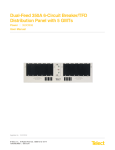
Dual-Feed 600A Load Center Frame
Power :: Models 600CB10 and 600CB12
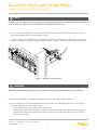
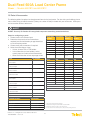
15. Also, test fuse alarm relay contacts at CB-F alarm terminals.
• Expect continuity (0Ω) between Terminals C and NC.
• Expect an open circuit (∞Ω) between Terminals C and NO.
16. Repeat Steps 13 and 14 to power up Side B. A PWR and B PWR LEDs must both be green.
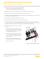
17. Make sure input power is off again before installing output wiring to this device.
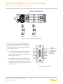
18. For output wiring, crimp dual-hole lugs onto one end of #10 to #2/0 AWG copper output wires, as required by
NEC. (Work with one output wire at a time.)
19. Insulate lug barrels with UL94 V-0 rated heat shrink tubing.
20. Clean the panel terminal and lugs with non-abrasive, non-metallic pad.
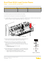
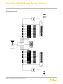
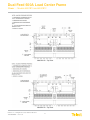
21. If required, lightly coat anti-oxidant on lugs and output BATT and RTN terminals, and then connect lugs to
terminals, as shown in Figure 10. (NEC specifies only one lug and load at each output terminal.) Tighten nuts
to no more than 50-in./lb. (5.6 N•m), max., and then connect other end of output wire to load.
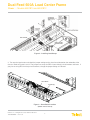
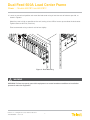
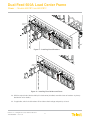
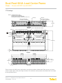
22. Install circuit breakers or fuses, as shown in Figures
11 and 12.
a. Use screws provided with circuit breaker or fuse
holder to attach cover to breaker or holder. (Use
the cover removed previously for circuit breakers.
The fuse holder requires a cover.)
b. Insert a breaker in the load center frame. ("Line"
is on top. Breaker is "upside down" so ON toggle
is up.) Or, insert holder in load center frame
("Load" is on top).
c. Fasten the cover to the load center using the
screw previously removed with the cover in Step 1.
d. If applicable, install fuse.
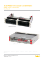
Figure 10 - Output Lug Connections
© Telect, Inc., All Rights Reserved, 136429-1 A0 07.14
1.509.926.6000 :: telect.com
10