1
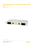
50A Dual-Feed 5/5 GMT
Total Front Access Fuse Panel
Power :: GMT05FA
User Manual
Applys to : GMT05FA
© Telect, Inc., All Rights Reserved, 131927-7-A0
1.509.926.6000 :: telect.com
50A Dual-Feed 5/5 GMT TFA Fuse Panel
Power :: Model GMT05FA
Table of Contents
1.1 Overview�������������������������������������������������������������������������������������������������������������������������3
1.2 Rack-mounting Considerations���������������������������������������������������������������������������������������4
1.3 Specifications������������������������������������������������������������������������������������������������������������������4
1.4 Installation�����������������������������������������������������������������������������������������������������������������������6
1.4.1 Installation Considerations�������������������������������������������������������������������������������������������6
1.4.2 Mounting the Panel�������������������������������������������������������������������������������������������������7
1.5 Accessories�������������������������������������������������������������������������������������������������������������������12
1.6 Assembly Drawing��������������������������������������������������������������������������������������������������������13
1.7 Schematic���������������������������������������������������������������������������������������������������������������������14
List of Figures
Figure 1 - Brackets Oriented for Wall Mounting�������������������������������������������������������������������� 3
Figure 2 - Brackets Oriented for Rack Mounting������������������������������������������������������������������ 3
Figure 3 - 23” Rack Mount,���������������������������������������������������������������������������������������������������7
Figure 4 - 19” Rack Mount,���������������������������������������������������������������������������������������������������7
Figure 5 - 19” Rack Mount Flush������������������������������������������������������������������������������������������7
Figure 6 - 23” Rack Mount Flush������������������������������������������������������������������������������������������7
Figure 7 - Rack Mounting�����������������������������������������������������������������������������������������������������8
Figure 8 - Wall Mounting�������������������������������������������������������������������������������������������������������8
Figure 9 - Ground Lug Connection���������������������������������������������������������������������������������������9
Figure 10 - Input Connections����������������������������������������������������������������������������������������������9
Figure 11 - Status LEDs & Alarm Terminals������������������������������������������������������������������������ 10
Figure 12 - Output Connections������������������������������������������������������������������������������������������ 11
Figure 13 - Installing GMT Fuses��������������������������������������������������������������������������������������� 11
© Telect, Inc., All Rights Reserved, 131927-7-A0
1.509.926.6000 :: telect.com
ii
50A Dual-Feed 5/5 GMT TFA Fuse Panel
Power :: Model GMT05FA
1.1 Overview
Figure 1 - Brackets Oriented for Wall Mounting
Figure 2 - Brackets Oriented for Rack Mounting
Telect’s 50A Dual-Feed 5/5 GMT Total Front Access Fuse Panel is a compact 1RU, EIA panel enabling
±24 and -48 Vdc power protection for a variety of local/remote central office, datacenter, and cell-tower
telecommunications equipment.
The panel provides total front access to inputs, outputs, alarms, LED indicators, and fuses. Its small form
factor — less than 2 in. (~ 50 mm) in depth — makes it ideal for mounting to either front or rear rack flange.
Re-orient mounting brackets to install on a wall.
Each of the 50A feeds provides power for up to 5 GMT-protected loads of up to 15A each. The GMT fuse blocks
are mounted upside-down so that the GMT indicator flag flips downward when activated, making identification
and detection easier, especially on tall racks. Holes for color coded fuse designation pins are located above each
fuse position.
© Telect, Inc., All Rights Reserved, 131927-7-A0
1.509.926.6000 :: telect.com
1
50A Dual-Feed 5/5 GMT TFA Fuse Panel
Power :: Model GMT05FA
Other features include power and fuse fail LEDs for each feed plus dry Form-C alarm connections for both power
and fuse failures. Visit our website (telect.com) or see Page 10 to order GMT fuses and fuse designation pins.
GMT05FA is listed by UL for USA and Canada, and NEBS (Level 3) certified.
1.2 Rack-mounting Considerations
1. Elevated Operating Ambient - If the equipment is installed in a closed or multi-unit rack assembly, the
operating ambient temperature of the rack environment may be greater than room ambient. Therefore, give
consideration to installing the equipment in an environment compatible with the maximum ambient temperature
(Tma) specified by the manufacturer.
2. Reduced Air Flow - Installation of the equipment in a rack should be such that the amount of air flow required
for safe operation of the equipment is not compromised.
3. Mechanical Loading - Mounting of the equipment in the rack should be such that a hazardous condition is not
achieved due to uneven mechanical loading.
4. Circuit Overloading - Consider the connection of the equipment to the supply circuit and the effect that
overloading of the circuits might have on overcurrent protection and supply wiring. Use appropriate consideration of equipment nameplate ratings when addressing this concern.
5. Maintain reliable earthing of rack-mounted equipment. Pay particular attention to supply connections other
than direct connections to the branch circuit (e.g., use of power strips).
1.3 Specifications
Inputs:
Specifications:
Max. Input Load Rating
50A
Voltage & Range
±20 VDC to -60 VDC @ 20°C
±22 VDC to -58 VDC @ 55°C
Max. Power Dissipation at Full Load
11W per side
% of Full Load Power Dissipation
less then 1%
Max. Input Interruption Device
60A
Input Terminals
Dual M5 studs on 5/8-in. centers. Torque KEPS nut
(using 5/16-in. or 8-mm socket) to ~20 in.-lb (~2.3
N•m).
Input Wire Size
© Telect, Inc., All Rights Reserved, 131927-7-A0
1.509.926.6000 :: telect.com
8 AWG for a 50A feed
2
50A Dual-Feed 5/5 GMT TFA Fuse Panel
Power :: Model GMT05FA
Outputs:
Specifications:
Max. GMT Output Load (ea.)
12A continuous
Max. GMT Output Fuse (ea.)
Max. Total GMT Output Per Side
Output Terminals
GMT Output Wire Size Range
15A
50A
10 Pairs of 6-32 panhead compression/wire-binding
terminals
#26 to #14 AWG, depending on output fuse (1/4A to 15A)
Alarms:
Specifications:
Max. Alarm Power Rating
@24V: 24 mA (0.58W)
@48V: 48 mA (2.30W)
Alarm Relay Contacts
Alarm Wire Size
Alarm Terminals
Amphenol-Type Connector (Unshielded) 64 Pins
Dry Form-C contacts (1A @ 30 Vdc)
Up to 16 AWG
# 3 panhead screws with wire-binding plates
Environmental:
Environmental: Specifications:
Physical (Nominal):
Specifications:
Weight (Installed)
3.6 lb (1.6 kg)
Operating Temperature Range
Width x Height x Depth
Weight (Shipping)
Material & Color
Mounting Options
Grounding:
Chassis GND Terminal Studs (With
KEPS Nuts) for Single-Hole Compression Lug
© Telect, Inc., All Rights Reserved, 131927-7-A0
1.509.926.6000 :: telect.com
-10°C (14°F) to 55°C (131°F)
17.25 x 1.75 x 2 in. (438 x 44 x 50 mm). See Page 11 for
details.
~4.0 lb (~1.8 kg)
Steel (grey powder coat)
Wall or EIA Rack (19 in. and 23 in.)
Specifications:
1/4”-20 stud. Torque KEPS nut (using 7/16-in. socket) to
~20 in.-lb (~2.3 N•m).
3
50A Dual-Feed 5/5 GMT TFA Fuse Panel
Power :: Model GMT05FA
1.4 Installation
!
ALERT
ALERT! Install this product within a restricted access location where access is through the use of a tool,
lock and key, or other means of security, and is controlled by the authority responsible for the location.
Only qualified personnel may install and maintain this product
!
ALERT
ALERT! Verify that all connections meet requirements specified in local electric codes or
operating company guidelines before supplying power. Protect this equipment with a fuse
or breaker sufficient to interrupt power levels specified under “Inputs” on the preceding
table of specifications.
1.4.1 Installation Considerations
Please read and understand all instructions before starting installation. If you have questions, contact Telect
Technical Support at [email protected] or call 1.509.926.6000.
When you receive the equipment, carefully unpack it and compare it to the packaging list. Please report any
defective or missing parts to Telect Quality at [email protected] or call 1.509.926.6000.
Telect is not liable for transit damaged. If the product is damaged, please report it to the carrier and contact
Telect Quality.
© Telect, Inc., All Rights Reserved, 131927-7-A0
1.509.926.6000 :: telect.com
4
50A Dual-Feed 5/5 GMT TFA Fuse Panel
Power :: Model GMT05FA
1.4.2 Mounting the Panel
NOTE: Panel brackets provide flush or extended mounting on an EIA, 19-in. or 23-in. rack. The
mounting brackets also allow for flush or extended mounting on a wall.
Procedure steps:
1. Install the brackets using the four screws included with brackets, as shown in the following illustrations.
2. Mount the panel using the screws provided, as shown.
Figure 3 - 23” Rack Mount,
Extended or Wall-Mounted
Figure 4 - 19” Rack Mount,
Extended or Wall-Mounted
Figure 6 - 23” Rack Mount Flush
Figure 5 - 19” Rack Mount Flush
© Telect, Inc., All Rights Reserved, 131927-7-A0
1.509.926.6000 :: telect.com
5
50A Dual-Feed 5/5 GMT TFA Fuse Panel
Power :: Model GMT05FA
• For rack mounting, locate an unused EIA rack
position, normally at the top of the rack. Mount the
panel to the rack using the four, 12-24 thread-cutting
screws and washers provided, as shown on the
right. Tighten the screws to 35 in.-lb (4.29 N•m).
• For wall mounting, use four appropriate fasteners
(and anchors, if needed) along with the #12
washers provided.
Figure 7 - Rack Mounting
It is best to mount the panel on a plywood board that
has been securely anchored to the wall. If you mount
the panel on a metal strut, in a cabinet, or onto other
metal objects, make sure to ground the metal object
along with the panel
Figure 8 - Wall Mounting
!
WARNING
WARNING! Failure to properly ground this equipment can create hazardous conditions to installation
personnel and to the equipment.
!
ALERT
ALERT! Only use components and crimping tools approved by agencies or certifying bodies recognized
in your country or region such as Underwriter’s Laboratories (UL), TUV, etc.
© Telect, Inc., All Rights Reserved, 131927-7-A0
1.509.926.6000 :: telect.com
6
50A Dual-Feed 5/5 GMT TFA Fuse Panel
Power :: Model GMT05FA
3. Use a listed (approved) crimping tool to attach a listed (approved), single-hole compression lug for a #10 stud
onto 14 AWG ground wire.
Figure 9 - Ground Lug Connection
4. If desired (highly recommended), lightly coat anti-oxidant on lug, grounding terminal, and surrounding
contacting surface.
5. Connect the lug using the M5 KEPS nut provided, as shown on the right. Tighten the KEPS nuts to
~20 in.-lb (~2.3 N•m).
6. The installer should verify that a readily accessible 60-amp maximum overcurrent protection device is part of
the building installation wiring feeding the fuse panel.
7. Make sure the input power is OFF (open breaker, dummy fuse, or open fuse holder at power distribution unit
[PDU]) before connecting this panel’s input cables to the PDU.
!
WARNING
WARNING! Before connecting input power cables, make sure input power to panel is turned off.
8. For input wiring — wiring used as inputs to this distribution panel — crimp the dual-hole compression lugs
onto #10 to #6 AWG conductors (min. 8 AWG for a 50A feed).
9. Insulate the lug barrels with UL94 V-0 rated heat-shrink tubing.
Dummy Fuses
Figure 10 - Input Connections
© Telect, Inc., All Rights Reserved, 131927-7-A0
1.509.926.6000 :: telect.com
7
50A Dual-Feed 5/5 GMT TFA Fuse Panel
Power :: Model GMT05FA
10. Remove (pull off) the input terminal covers.
11. Clean terminals and lugs with a nonabrasive, nonmetallic cloth, or pad.
12. If desired (highly recommended), lightly coat anti-oxidant on lugs, terminals, and contacting surfaces, and
then connect lugs to input terminals on panel.
13. Torque the KEPS nuts to ~20 in.-lb (~2.3 N•m).
14. Re-install the input terminal covers.
15. Make sure the GMT fuse positions are either empty or contain dummy fuses (phoney, inoperative all-plastic slugs).
16. Enable the fuse or breaker at the PDU (60A max.) to turn on Feed A to Side A of panel and then check voltage
and polarity at input connectors of panel. Also, check that
• PWR A LED on front of panel turns ON (green).
• PWR B and both FUSE LEDs must be OFF.
17. With PWR A lit (green for normal operation) — but with PWR B LED off — test power-fail relay and contacts at
PWR FAIL terminals on panel:
• Expect an open circuit (00Ω) between Terminals C and NC.
• Expect continuity (0Ω) between Terminals C and NO.
18. Test the fuse alarm relay contacts at FUSE ALM terminals.
• Expect continuity (0Ω) between Terminals C and NC.
• Expect an open circuit (00Ω) between Terminals C and NO.
19. Repeat Steps 16 and 17 to power up Side B.
• PWR A and PWR B must both be green.
20. With PWR A and B lit, test power-fail relay and contacts at PWR FAIL terminals.
• Expect continuity (0Ω) between Terminals C and NC.
• Expect an open circuit (∞Ω) between Terminals C and NO.
21. Make sure none of the fuse positions contain real, operable fuses.
Figure 11 - Status LEDs & Alarm Terminals
© Telect, Inc., All Rights Reserved, 131927-7-A0
1.509.926.6000 :: telect.com
8
50A Dual-Feed 5/5 GMT TFA Fuse Panel
Power :: Model GMT05FA
22. For GMT output wiring, use #24 to #14 AWG
copper wire. (Work with one wire at a time.) At this
end of the wire, either
• Crimp a single-hole ring or fork lug, as required by NEC.
OR
• Strip 3/8 in. (10 mm) of insulation for a bare-wire
connection.
23. Clean the panel terminals and lug (if applicable) with
a nonabrasive, non metallic cleaning pad.
24. If required, lightly coat anti-oxidant on lug/wire and
output BATTERY and RETURN terminals, and then
connect to the terminals. (NEC specifies only one
load at each output terminal.)
Figure 12 - Output Connections
25. Tighten the panhead screws to no greater than 8 in.-lb
(~1 N•m) and then connect the other end of the
output wire to load.
!
ALERT
ALERT! GMT fuses have a small inherent electrical resistance resulting in a small inherent power loss.
For this reason, the GMT fuse manufacturer recommends that the load for GMT fuses up to and including
7.5A not exceed 80% of the fuse rating and that the load for GMT fuse sizes between 10A and 15A
not exceed 70% of the fuse rating. For example, the load for a 15A GMT fuse should not exceed 10.5A
(15A x .70 = 10.5A).
The TOTAL LOAD FOR ALL FUSE OUTPUTS ON EACH SIDE must NOT exceed 50A.
26. Make sure load devices are off (disabled) and then
install the GMT fuses. Remember to install the GMT
fuses so that the failure indication flags are at the
bottom, as shown in the following illustration.
Holes are for Colored
Fuse Designation Pins
27. Test power and polarity at input of each equipment load.
28. If possible, replace one of the operable GMT
fuses with a blown fuse to verify that the FUSE
Alarm LED and FUSE ALM terminals are also as
specified above.
Dummy Fuse
29. Re-install the operable GMT fuse before proceeding.
30. If desired, connect the remote external audio/
visual alarm indicator wires (solid or tinned wires,
#22 to #18 AWG) to PWR ALARM and FUSE
ALM terminals.
GMT Fuse
Figure 13 - Installing GMT Fuses
31. Enable the equipment loads one at a time to verify
proper operation of loads.
This procedure is complete
© Telect, Inc., All Rights Reserved, 131927-7-A0
1.509.926.6000 :: telect.com
9
50A Dual-Feed 5/5 GMT TFA Fuse Panel
Power :: Model GMT05FA
1.5 Accessories
The following lists optional and replacement items for the panel. For compression lugs, please refer to Wire Sizing
& Label Convention Chart (Telect Part No. 117995) included with your panel
!
WARNING
WARNING! Use only UL-listed fuses or UL-recognized component secondary protection devices.
For dummy fuses, order part number 132748. For GMT safety (splash/splatter) covers, order part number
116915. Telect recommends using only UL-recognized supplementary protectors.
Table 1 - GMT Fuses
GMT Fuse
.18A Yellow (YEL)
¼A Violet (VIO)
½A Red (RED)
¾A Brown (BRN)
1A Gray (GRY)
11/3A White (WHT)
1½A White/Yellow (WHT/YEL)
2A Orange (ORN)
2.5A White/Orange (WHT/ORN)
3A Blue (BLU)
3.5A White/Blue (WHT/BLU)
4A White/Brown (WHT/BRN)
5A Green (GRN)
7½A Black/White (BLK/WHT)
10A Red/White (RED/WHT)
12A Yellow/Green (YEL/GRN)
15A Red/Blue (RED/BLU)
Part Numbers
GMT Fuse
Colored Designation
Pin Part No.
100151
102435-2
130781
102435-21
004001
102435-5
004008
102435-7
100991
102435-8
004006
102435-9
004011
102435-10
004002
102435-11
130783
102435-12
004012
102435-13
130782
102435-14
004013
102435-15
004014
102435-16
004010
102435-17
004015
102435-18
102287
102435-19
102288
102435-20
Table 2 - Input Lugs for Stranded Copper Conductors
(Straight Dual-Hole Lugs for #10 Studs on 5/8” Centers)
Manufacturer
#6 AWG
#8 AWG
Panduit
LCD6-10A-L
(Panduit/T&B Die Code 24)
(Burndy Die Code 7)
LCD8-10A-L
(Panduit/T&B Die Code 21)
(Burndy Die Code 49)
T&B
Burndy
256-30695-1183
(T&B Die Code 24)
YA6CL2TC10
(Burndy Die Code 7)
© Telect, Inc., All Rights Reserved, 131927-7-A0
1.509.926.6000 :: telect.com
10
54204
(T&B Die Code 49)
YA8CL2TC10
(Burndy Die Code 49)
© Telect, Inc., All Rights Reserved, 131927-7-A0
1.509.926.6000 :: telect.com
1.72 [43.7] 1.25 [31.8]
1.98 [50.4]
2.88 [73.2]
11
TN
TT
2
3
4
5
0.32 [8.1]
GMT TYPE FUSE ONLY 15A MAX
1
17.25 [438.2]
TOP VIEW
B
BATT
FUSE RTN
PWR
0.19 [4.8]
NO C NC NO C NC
PWR FAIL
FRONT VIEW
19.00 [482.6]
2
3
4
5
RTN
BATT
#3 Slot-Head Screws
0.63 [15.9]
GMT TYPE FUSE ONLY 15A MAX
1
10-32 Studs with
KEPS Nuts & Washers
B
INPUT
MAX
50A
+/-24/48
VDC
Lug must be no wider
than 0.50 in. (12.8 mm)
0.25 [6.4]
1.6 Assembly Drawing
18.31 [465.1]
#6-32 Slot-Head Screws
A
FUSE ALM
www.telect.com
PWR
RTN FUSE
BATT
M5 Ground Stud with KEPS Nut & Washer
NOTE: All dimensions are in in. [mm].
50A Dual-Feed 5/5 GMT TFA Fuse Panel
Power :: Model GMT05FA
50A Dual-Feed 5/5 GMT TFA Fuse Panel
Power :: Model GMT05FA
1.7 Schematic
BATT
INPUT A
RTN
C GND
1
2
3
GMT OUTPUT A
BATT
4
5
1
2
3
4
NO
INPUT A PWR
C
FUSE ALARM A
ALARM PCB
FUSE ALARM B
INPUT B PWR
PWR FAIL
GMT OUTPUT A
RTN
5
NC
NC
C
FUSE ALARM
NO
1
2
3
GMT OUTPUT B
RTN
4
5
1
2
3
GMT OUTPUT B
BATT
4
5
BATT
INPUT B
RTN
Telect assumes no liability for the application or use of these products. Neither does Telect convey any license
under its patent rights or the patent rights of others. This document and the products described herein are subject
to change without notice.
© Telect, Inc., All Rights Reserved, 131927-7-A0
1.509.926.6000 :: telect.com
12