1
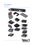
Dual-Feed 350A 6-Circuit Breaker/TFD
Distribution Panel with 5 GMTs
Power :: 350CB06
User Manual
Applies to : 350CB06
© Telect, Inc., All Rights Reserved, 138661-3 A0 07/14
1.509.926.6000 :: telect.com
Table of Contents
1.1 Overview .........................................................................................................................3
1.2 Important Installation Guidelines .....................................................................................4
1.3 Specifications ..................................................................................................................5
1.4 Inspection ........................................................................................................................7
1.5 Installation .......................................................................................................................7
1.6 Parts & Accessories ...................................................................................................... 15
1.7 Schematic Drawing ....................................................................................................... 17
1.8 Drawings ....................................................................................................................... 18
List of Figures
Figure 1 - 350CB06 Distribution Panel..................................................................................3
Figure 2 - Bracket Orientation ...............................................................................................7
Figure 3 - Rack Mounting ......................................................................................................8
Figure 4 - Ground to Chassis ................................................................................................9
Figure 5 - Input Lug Connections ........................................................................................ 10
Figure 6 - Alarm Faceplate .................................................................................................. 10
Figure 7 - CB/TFD Output Lug Connections ....................................................................... 11
Figure 8 - GMT Output Lug Connections ............................................................................ 12
Figure 9 - Installing Circuit Breaker ..................................................................................... 13
Figure 10 - Installing GMT Fuses ........................................................................................ 13
Figure 11 - Designation Card .............................................................................................. 14
Dual-Feed 350A 6-Circuit Breaker/TFD
Distribution Panel with 5 GMTs
Power :: 350CB06
1.1 Overview
Telect’s Dual-Feed 350A Circuit Breaker/TFD Panel
provides high-capacity protection for secondary power
distribution, co-locations, and data and communications
equipment. In addition, the provided GMT fuses enhance
power distribution for applications that require 15A or
less. Each of the dual feeds contains six interrupter
positions for either bullet-style REC switch (ON/OFF)
circuit breakers or TFD holders. Each feed also includes
five GMT fuses. Go to telect.com to order circuit breakers,
TFD holders, and GMT fuses:
Figure 1 - 350CB06 Distribution Panel
• TLS fuses up to 70A rated, continuous current 80% of rated
• TPS fuses up to 125A rated, continuous current 80% of rated
• GMT fuses up to 15A rated, continuous current 70% of rated
• Circuit breakers up to 100A rated, continuous current 80% of rated
This panel ships with solid covers over the circuit breaker/TFD holder positions and with fuse-slot fillers in the
GMT holders.
Sides A and B are electrically isolated except for the replaceable alarm card, which contains power and alarm
LEDs. The panel features separate power status LEDs and a single-alarm LED for breaker trips or fuse failures.
Power and alarm relay connections are controlled on-board and provide dry Form-C contacts.
All input, output, and alarm terminals are on the rear, and all are covered by a single, full-size transparent terminal
cover. Separate input terminal sub-covers maintain protection for the other terminals when you are only working
with the load and/or alarm terminals. Two pairs of ground studs on the rear panel provide flexibility in grounding
from either side of the rack. The input,output, and ground studs support the following cable gauges:
• Input terminals support up to a 750-MCM cable.
• Output terminals support up to a 2-AWG cable.
• Ground studs support up to a 1-AWG cable.
© Telect, Inc., All Rights Reserved, 138661-3 A0 07/14
1.509.926.6000 :: telect.com
3
Dual-Feed 350A 6-Circuit Breaker/TFD
Distribution Panel with 5 GMTs
Power :: 350CB06
1.2 Important Installation Guidelines
• Elevated Operating Ambient - If installed in a closed or multi-unit rack assembly, the operating ambient
temperature of the rack environment may be greater than room ambient. Therefore, consideration should be
given to installing the equipment in an environment compatible with the maximum ambient temperature (Tma)
specified by the manufacturer.
• Reduced Air Flow - Installation of the equipment in a rack should be such that the amount of air flow required
for safe operation of the equipment is not compromised.
• Mechanical Loading - Mounting of the equipment in the rack should be such that a hazardous condition is
not achieved due to uneven mechanical loading.
• Circuit Overloading - Consideration should be given to the connection of the equipment to the supply circuit
and the effect that overloading of the circuits might have on overcurrent protection and supply wiring.
Appropriate consideration of equipment nameplate ratings should be used when addressing this concern.
• Reliable Earthing - Reliable earthing of rack-mounted equipment should be maintained. Particular attention should be given to supply connections other than direct connections to the branch circuit (e.g. use of power
strips).
• Disconnect Device - A readily disconnect device shall be incorporated in the building installation wiring.
© Telect, Inc., All Rights Reserved, 138661-3 A0 07/14
1.509.926.6000 :: telect.com
4
Dual-Feed 350A 6-Circuit Breaker/TFD
Distribution Panel with 5 GMTs
Power :: 350CB06
1.3 Specifications
Inputs:
Specifications:
Voltage Range (Nominal Voltage)
±20V to ±30V (Nominal ±24Vdc)
-40V to -60V (Nominal -48Vdc)
Max Input Load Rating
350A @ +50°C
300A @ +55°C
Short Circuit Withstand Rating
5000A
Nominal Power Loss at Full Load
Less than 40W per side @ 16,800W full load per
side (350Ax48V)
Max. Input Interrupt Device
440A
Input Terminal Studs (With Nuts, Flat Washers, &
Spring Washers) for Dual-Hole Compression Lugs
3/8-16 studs on 1 in. centers [max lug width of
1.625 in. (41.3mm)]. Torque nuts (using 9/16 in.
or 15 mm wrench) to 140 in-lb (15.5 N • m).
Input Wire Size
#1 AWG to 750 MCM
Breaker/Fuse Outputs:
Specifications:
Max. Output Single-Pole, Long-Delay
Circuit Breaker (ea.)
100A
Max. Output TFD Holder, Schematic C
125A (TLS fuse)
70A (TPS fuse)
Max Continuous Output Load (each)
80% of rated
Min. Short Circuit Interrupt Rating
5000A
Max. Total Output Load
300A per side
Output Terminal Studs (With KEPS Nuts and
Washers) for Dual-Hole Compression Lugs
10-32 studs on 5/8 in. centers [max lug width of
0.6 in. (15.2 mm). Torque nuts (using 3/8 in. or
10 mm wrench) to 20 in-lb (2.27 N • m).
Output Wire Size
#6 AWG to #2 AWG
GMT Outputs:
Specifications:
Max. Rated Output GMT Fuse (each)
15A
Max. Continuous Output Load (each)
70% of rated
Max. Total Output Load
50A per side
Output Terminals for Compression Lugs
6-32 pan-head screws [max lug width of 0.32 in.
(8.1 mm)]. Torque to 6.3 in-lb (0.7 N • m).
Output Wire Size*
#22 AWG to #12 AWG
© Telect, Inc., All Rights Reserved, 138661-3 A0 07/14
1.509.926.6000 :: telect.com
5
Dual-Feed 350A 6-Circuit Breaker/TFD
Distribution Panel with 5 GMTs
Power :: 350CB06
Grounding:
Specifications:
Earth GND Terminal Studs for Dual-Hole
Compression Lugs
¼-20 studs on 5/8 in. centers. Torque nuts
(using 7/16 in. or 12 mm wrench) to 25 in-lb
(2.83 N • m).
Ground Wire Size
Up to #1 AWG
Alarms:
Specifications:
Alarm Relay Contacts
2A @ 30Vdc
0.6A @ 60Vdc
Max. Alarm Card Power Rating
@24V: 40 mA (.96W)
@48V: 58 mA (2.78W)
Alarm Wire Size
#18 AWG to #22 AWG
Alarm Terminals
Wire wrap
Dimensions:
Specifications:
Nominal, without brackets:
Width: 17.25 in. (438 mm)
Height: 5 in. (127 mm)
Depth: 8 in. (203 mm)
Weight:
Specifications:
Without Packaging and Accessories
19 lb (8.6 kg)
Shipping
22 lb (10 kg)
Environment:
Specifications:
Operating Temperature
-10°C (14°F) to 55°C (131°F)
Humidity
90% and noncondensing
!
ALERT
ALERT! Verify that all connections meet requirements specified in local electric codes or operating
company guidelines before supplying power. Protect this equipment with a fuse or breaker sufficient to
interrupt power levels specified on the preceding pages.
Install this product within a restricted access location where access is through the use of a tool, lock
and key, or other means of security and is controlled by the authority responsible for the locaiton. Only
qualified technicians may install and maintain this product.
© Telect, Inc., All Rights Reserved, 138661-3 A0 07/14
1.509.926.6000 :: telect.com
6
Dual-Feed 350A 6-Circuit Breaker/TFD
Distribution Panel with 5 GMTs
Power :: 350CB06
1.4 Inspection
Please read and understand all instructions before starting installation. If you have questions, contact Telect
Technical Support at [email protected] or call 1.509.926.6000.
When you receive the equipment, carefully upack it and compare it to the packaging list. Please report any
defective or missing parts to Telect Quality at [email protected] or call 1.509.926.6000.
Telect is not liable for transit damaged. If the product is damaged, please report it to the carrier and contact
Telect Quality.
1.5 Installation
Panel brackets provide flush, 2-in. extended, or 4-in. extended EIA, or WECO mounting in a 19-or 23-in. rack.
Procedure steps:
1.
Use the six screws provided to fasten the brackets to the panel, as shown in the following two illustrations.
Figure 2 - Bracket Orientation
© Telect, Inc., All Rights Reserved, 138661-3 A0 07/14
1.509.926.6000 :: telect.com
7
Dual-Feed 350A 6-Circuit Breaker/TFD
Distribution Panel with 5 GMTs
Power :: 350CB06
Figure 3 - Rack Mounting
2. Locate an unused rack position and mount the panel using at least two sets of fasteners (screws and star
washers provided) per side, as shown in Figure 3. (Mount the panel as high as possible on the rack.)
3. Tighten the screws to 35 in.-lb (4.29 N•m).
If you intend on installing more than one panel per rack, you need to plan a rack arrangement that dissipates
heat efficiently, as suggested on the following page.
4. Loosen (you need not remove) the two screws securing the transparent terminal cover to the rear of the panel.
5. Remove the cover.
!
WARNING
WARNING! Failure to properly ground this equipment can create hazardous conditions to installation personnel and to the equipment.
© Telect, Inc., All Rights Reserved, 138661-3 A0 07/14
1.509.926.6000 :: telect.com
8
Dual-Feed 350A 6-Circuit Breaker/TFD
Distribution Panel with 5 GMTs
Power :: 350CB06
!
ALERT
ALERT! Only use components and crimping tools
approved by agencies or certifying bodies
recognized in your country or region such as
Underwriter’s Laboratories (UL), TUV, etc.
6. Use a listed (approved) crimping tool to attach a
listed (approved), dual-hole compression lug onto
suitable ground wire. (The size of the ground
depends on the input interruption device.)
7.
If required, lightly coat an anti-oxidant on the lug
and grounding surface on the rear of the panel.
8. Connect using ¼ - 20 hex nuts and flat washers
provided, as shown in Figure 4.
9. Tighten the bolt to 25 in.-lb (2.83 N•m), max.
!
WARNING
WARNING! Before connecting input power cables,
make sure input power to panel is turned off.
10. Make sure the input power is off (open breaker,
dummy fuse, or open fuse holder at primary power
distribution unit or battery) before connecting this
panel’s input cables to the PDU or battery.
Figure 4 - Ground to Chassis
11. For input wiring — wiring used as inputs to this load
center — crimp dual-hole compression
lugs onto #1-AWG to 750-MCM copper wires.
The choice of input wiring depends on the
following criteria:
• The input interrupt device rating affects the size of
the input wiring.
• Ambient operating temperature affects the type of
input wire insulation. For further information consult
the National Electrical Code (NEC).
© Telect, Inc., All Rights Reserved, 138661-3 A0 07/14
1.509.926.6000 :: telect.com
9
Dual-Feed 350A 6-Circuit Breaker/TFD
Distribution Panel with 5 GMTs
Power :: 350CB06
12. Insulate lug barrels with UL94 V-0-rated heat
-shrink tubing.
13. Clean the terminals and lugs with a nonabrasive,
nonmetallic pad.
14. If required, lightly coat an anti-oxidant on the lugs
and input BATT and RETURN terminals.
15. Connect the lugs to input terminals on the back of
the panel, as shown in Figure 5.
16. Tighten the lugs to 140 in.-lb (~15.5 N•m), max.
17. Make sure all interrupter positions are either empty,
off, or contain dummy fuses (phoney, inoperative
all-plastic slugs).
18. Enable the fuse or breaker at the primary distribution unit or battery (440A max.) to turn on Feed A
to Side A of the panel and then check the voltage
and polarity at input connectors of panel. Also, check
that
Figure 5 - Input Lug Connections
• POWER A LED on the front of the panel turns
on (green).
• POWER B LED is off.
19. Repeat the previous step with Feed B and verify
POWER B LED.
POWER
20. With POWER A and B LEDs green (normal operation),
test power-fail relay and contacts at POWER FAIL
alarm terminals on the rear of the panel:
A
• Expect continuity (0Ω) between Terminals C and
NC.
ALARM
• Expect an open circuit (00Ω) between Terminals C
and NO.
POWER
21. Test fuse alarm relay contacts at ALARM (CB/Fuse
Alarm) terminals on the rear of the panel.
B
• Expect continuity (0Ω) between Terminals C and
NC.
• Expect an open circuit (00Ω) between Terminals C
and NO.
© Telect, Inc., All Rights Reserved, 138661-3 A0 07/14
1.509.926.6000 :: telect.com
Figure 6 - Alarm Faceplate
10
Dual-Feed 350A 6-Circuit Breaker/TFD
Distribution Panel with 5 GMTs
Power :: 350CB06
22. Make sure none of the interrupter positions contains operable devices.
23. For circuit breaker, or TPS/TLS output wiring, crimp dual-hole lugs onto one end of the #6- to #2-AWG
copper output wires, as required by NEC. (Work with one output wire at a time.)
24. Insulate lug barrels with UL 94V-0-rated heat-shrink tubing.
25. Clean panel terminals and lugs with a nonabrasive, nonmetallic pad.
26. If required, lightly coat anti-oxidant on the lugs and output BATT and RETURN terminals, and then connect
the lugs to the terminals, as shown in Figure 7. (NEC specifies only one lug and load at each output terminal.)
27. Tighten nuts to 20 in.-lb (~2.3 N•m), max.
28. Connect the other end of the output wire to load.
Compression
lug
1
1
2
Combination
nuts
Torque 10 32 KEPS nuts
to 20 in-lb [2.27 N-m]
Note: Clean all
contact surfaces
Figure 7 - CB/TFD Output Lug Connections
© Telect, Inc., All Rights Reserved, 138661-3 A0 07/14
1.509.926.6000 :: telect.com
11
Dual-Feed 350A 6-Circuit Breaker/TFD
Distribution Panel with 5 GMTs
Power :: 350CB06
29. For GMT output wiring, use #22- to #12-AWG
copper wire. (Work with one wire at a time.) At the
panel end of the wire, crimp a single-hole ring or
fork lug, as required by the NEC.
30. Clean the panel terminals and lug (if applicable)
with a nonabrasive, nonmetallic pad.
31. If required, lightly coat anti-oxidant on the lug/wire
and output BATT and RETURN terminals, and then
connect to terminals, as shown in Figure 8. (NEC
specifies only one load at each output terminal.)
32. Tighten the panhead screws to no more than 6.3
in.-lb. (~0.7 N•m).
Figure 8 - GMT Output Lug Connections
33. Connect the other end of the output wire to load.
!
ALERT
ALERT! GMT fuses have a small inherent electrical resistance resulting in a small inherent power
loss. For this reason, the GMT fuse manufacturer recommends that the load for GMT fuses up to and
including 7.5A not exceed 80% of the fuse rating and that the load for GMT fuse sizes between 10A
and 15A not exceed 70% of the fuse rating. For example, the load for a 15A GMT fuse should not
exceed 10.5A (15A x .70 = 10.5A).
34. Make sure the circuit breakers or fuse holders are switched off, empty, or contain dummy devices. Also make
sure load devices and/or distribution units are disabled. (Normally, circuit breakers are OFF when the switch
operator [handle] is down.) Then install circuit breakers or fuse holders and fuses for the dual-hole lug outputs,
as shown in Figure 9.
35. Again, make sure the load devices are disabled and then install the GMT fuses, as shown.
© Telect, Inc., All Rights Reserved, 138661-3 A0 07/14
1.509.926.6000 :: telect.com
12
Dual-Feed 350A 6-Circuit Breaker/TFD
Distribution Panel with 5 GMTs
Power :: 350CB06
If possible, avoid placing high-current circuit breakers side-by-side. Not doing so causes concentrated heat
collection and subsequent power loss. Also, if not all circuit breaker positions are occupied, allow non-populated
positions between breakers.
Cover plate
Circuit
breaker
Mounting
screw
Breaker cover plate
Figure 9 - Installing Circuit Breaker
Figure 10 - Installing GMT Fuses
Install the GMT fuses so that the failure indicator flags are at the top.
36. Do one of the following:
• Switch breakers to ON, or
• Install fuses.
Then test power and polarity at input of each equipment load or distribution unit fed by a circuit breaker or fuse.
© Telect, Inc., All Rights Reserved, 138661-3 A0 07/14
1.509.926.6000 :: telect.com
13
Dual-Feed 350A 6-Circuit Breaker/TFD
Distribution Panel with 5 GMTs
Power :: 350CB06
37. If possible, temporarily replace one of the operable GMT fuses with a blown fuse to check that the applicable
ALARM LED lights up red. Also, check the ALARM terminal on the rear of the panel:
• Expect an open circuit (00Ω) between Terminals C and NC.
• Expect continuity (0Ω) between Terminals C and NO.
Re-install the operable GMT fuse before proceeding.
38. Record circuit assignments in accordance with operating company procedures and guidelines.
The manufacturer’s designation card, shown below, is a 10-in. (254 mm) by 2¼-in. (57 mm) card that folds in
half to fit a card holder located to the right of the status LEDs.
SIDE A
POS AMP
FUSE TYPE
DESCRIPTION
POS AMP
RACK/BAY #
DESCRIPTION
SIDE B
POS AMP
FUSE TYPE
DESCRIPTION
POS AMP
RACK/BAY #
DESCRIPTION
Figure 11 - Designation Card
39. Re-install the terminal cover.
40. Lastly, enable equipment loads one at a time to verify the proper operation of loads.
41. This procedure is complete.
NOTE: For service or warranty, see our telect.com website and click on the “Support” tab, email inquiries to
[email protected], or phone us at 800-551-4567 (domestic only) or 509-926-8915.
© Telect, Inc., All Rights Reserved, 138661-3 A0 07/14
1.509.926.6000 :: telect.com
14
Dual-Feed 350A 6-Circuit Breaker/TFD
Distribution Panel with 5 GMTs
Power :: 350CB06
1.6 Parts & Accessories
The following tables list optional and replacement items for the panel. For wire sizing and labeling, please refer to
Wire Sizing & Label Convention Chart (Telect Part No. 117995) included with your panel.
!
WARNING
WARNING! Use only UL-listed or UL-recognized component secondary protection devices.
Table 1 - Accessories
Item
Description
Part Number
Alarm card
Standard
400223
Face plate
Circuit breaker face plate
090-0001-0002
Face plate blank
Replacement face plate blank
090-0001-0003
Circuit breakers
10 amp long delay
090-0052-0010
20 amp long delay
090-0052-0020
30 amp long delay
090-0052-0030
40 amp long delay
090-0052-0040
50 amp long delay
090-0052-0050
60 amp long delay
090-0052-0060
70 amp long delay
090-0052-0070
80 amp long delay
090-0052-0080
90 amp long delay
090-0052-0090
100 amp long delay
090-0052-0100
Input terminal
compression lugs
1/0 AWG or #1 Weld Wire
116108
2/0 AWG or 1/0 Weld Wire
116109
3/0 AWG or 2/0 Weld Wire
116110
2 AWG
114552
4 AWG
110516
6 AWG
101686
TFD Fuse Holder Kit
For TPS/TLS fuses
090-0001-0033
GMT Fuse Puller (Recommended)
Medium-Duty, Tweezer-Style
Tool for Removing GMT Fuses
06113-03
GMT Phoney Fuse
Dummy Plastic Slug
132748
GMT Fuse Safety Cover
Solder Splash Protection
116915
Ground and output terminal
compression lugs
Telect assumes no liability from the application or use of these products. Neither does Telect convey any license
under its patent rights or the patent rights of others. This document and the products described herein are subject
to change without notice.
© Telect, Inc., All Rights Reserved, 138661-3 A0 07/14
1.509.926.6000 :: telect.com
15
Dual-Feed 350A 6-Circuit Breaker/TFD
Distribution Panel with 5 GMTs
Power :: 350CB06
!
ALERT
ALERT! Only use components and crimping tools approved by agencies or certifying bodies recognized
in your country or region such as Underwriter’s Laboratories (UL), TUV, etc.
Table 2 - TPS Fuse
Item
Description
Part Number
TPS Fuse
5A
129816
10A
130481
15A
130485
20A
130487
25A
130489
30A
130476
40A
130478
50A
130484
60A
130486
70A
130488
Table 3 - GMT Fuses
Item
Description
GMT Fuses
.18A Yellow (YEL)
130781
102435-21
.25A Violet (VIO)
100151
102435-2
.5A Red (RED)
004001
102435-5
.75A Brown (BRN)
004008
102435-7
1A Gray (GRY)
100991
102435-8
1.33A White (WHT)
004006
102435-9
1.5A White/Yellow (WHT/YEL)
004011
102435-10
2A Orange (ORN)
004002
102435-11
2.5A White/Orange (WHT/ORN)
130783
102435-12
3A Blue (BLU)
004012
102435-13
3.5A White/Blue (WHT/BLU)
130782
102435-14
4A White/Brown (WHT/BRN)
004013
102435-15
5A Green (GRN)
004014
102435-16
7.5A Black/White (BLK/WHT)
004010
102435-17
10A Red/White (RED/WHT)
004015
102435--18
12A Yellow/Green (YEL/GRN)
102287
102435-19
15A Red/Blue (RED/BLU)
102288
102435-20
© Telect, Inc., All Rights Reserved, 138661-3 A0 07/14
1.509.926.6000 :: telect.com
Part Number
of Fuse
16
Part Number of Colored
Designation Pin
Dual-Feed 350A 6-Circuit Breaker/TFD
Distribution Panel with 5 GMTs
Power :: 350CB06
1.7 Schematic Drawing
BATT
RTN
6
A
Input
5
4
3
RTN
2
1
6
5
4
BATT
3
2
1
C GND
INPUT POWER A
GREEN
BREAKER ALARM
RED
NO
ALARM
CIRCUIT
INPUT POWER B
c
NC
NC
C
NC
POWER
ALARM
Note: Relays shown
in alarm condition
BREAKER
FAIL
GREEN
C GND
1
2
3
BATT
4
5
6
1
2
3
4
RTN
5
B
6
RTN
BATT
© Telect, Inc., All Rights Reserved, 138661-3 A0 07/14
1.509.926.6000 :: telect.com
17
Input
Dual-Feed 350A 6-Circuit Breaker/TFD
Distribution Panel with 5 GMTs
Power :: 350CB06
1.8 Drawings
( 19.000 )
( 17.250)
( 4.970 )
Front View
( 9.855 )
( 8.140 )
Top View
Rear View
© Telect, Inc., All Rights Reserved, 138661-3 A0 07/14
1.509.926.6000 :: telect.com
18