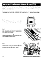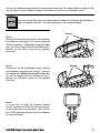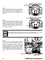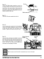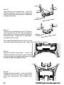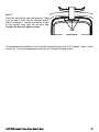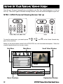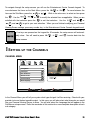
1
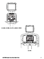
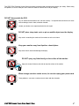
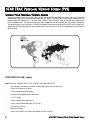
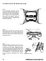
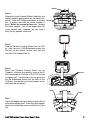
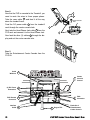
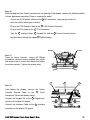
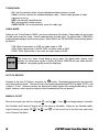
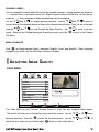
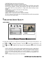
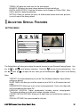
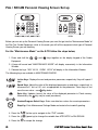
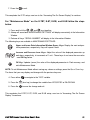
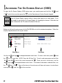
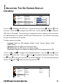
STAR TRAC FITNESS
TM
PERSONAL VIEWING SCREEN
OWNER’S MANUAL
TABLE
OF
CONTENTS
Introduction . . . . . . . . . . . . . . . . . . . . . . . . . . . . . . . . . . . . . . . . . . . . . . . . . . . . . . . . . . . . . . . . . . . . . . . . . . . . . . . . . . . . . .
About This Manual . . . . . . . . . . . . . . . . . . . . . . . . . . . . . . . . . . . . . . . . . . . . . . . . . . . . . . . . . . . . . . . . . . . . . . . . .
Before You Get Started . . . . . . . . . . . . . . . . . . . . . . . . . . . . . . . . . . . . . . . . . . . . . . . . . . . . . . . . . . . . . . . . . . . . . . . . . . . . .
Check Facilities Preparedness . . . . . . . . . . . . . . . . . . . . . . . . . . . . . . . . . . . . . . . . . . . . . . . . . . . . . . . . . . . . . . .
Equipment Layout . . . . . . . . . . . . . . . . . . . . . . . . . . . . . . . . . . . . . . . . . . . . . . . . . . . . . . . . . . . . . . . . . . . . . . . . .
Input Signals . . . . . . . . . . . . . . . . . . . . . . . . . . . . . . . . . . . . . . . . . . . . . . . . . . . . . . . . . . . . . . . . . . . . . . . . . . . . .
Cabling . . . . . . . . . . . . . . . . . . . . . . . . . . . . . . . . . . . . . . . . . . . . . . . . . . . . . . . . . . . . . . . . . . . . . . . . . . . . . . . . . .
Power Receptacles . . . . . . . . . . . . . . . . . . . . . . . . . . . . . . . . . . . . . . . . . . . . . . . . . . . . . . . . . . . . . . . . . . . . . . . .
Warnings and Cautions . . . . . . . . . . . . . . . . . . . . . . . . . . . . . . . . . . . . . . . . . . . . . . . . . . . . . . . . . . . . . . . . . . . . . . . . . . . . .
STAR TRAC Personal Viewing Screen (PVS) . . . . . . . . . . . . . . . . . . . . . . . . . . . . . . . . . . . . . . . . . . . . . . . . . . . . . . . . . . .
Unpack Your PVS . . . . . . . . . . . . . . . . . . . . . . . . . . . . . . . . . . . . . . . . . . . . . . . . . . . . . . . . . . . . . . . . . . . . . . . . .
NTSC/ATSC Kit . . . . . . . . . . . . . . . . . . . . . . . . . . . . . . . . . . . . . . . . . . . . . . . . . . . . . . . . . . . . . . . . . . . . . . . . . . .
PAL/SECAM Kit . . . . . . . . . . . . . . . . . . . . . . . . . . . . . . . . . . . . . . . . . . . . . . . . . . . . . . . . . . . . . . . . . . . . . . . . . . .
Tools Needed . . . . . . . . . . . . . . . . . . . . . . . . . . . . . . . . . . . . . . . . . . . . . . . . . . . . . . . . . . . . . . . . . . . . . . . . . . . . .
Installing Your STAR TRAC Personal Viewing Screen (PVS) . . . . . . . . . . . . . . . . . . . . . . . . . . . . . . . . . . . . . . . . . . . . . .
E-UB, E-RB, E-TBT, and E-ST . . . . . . . . . . . . . . . . . . . . . . . . . . . . . . . . . . . . . . . . . . . . . . . . . . . . . . . . . . . . . . .
E-TR . . . . . . . . . . . . . . . . . . . . . . . . . . . . . . . . . . . . . . . . . . . . . . . . . . . . . . . . . . . . . . . . . . . . . . . . . . . . . . . . . . . .
Setting Up Your STAR TRAC Personal Viewing Screen (PVS) . . . . . . . . . . . . . . . . . . . . . . . . . . . . . . . . . . . . . . . . . . . . .
NTSC/ATSC (typically US, Japan) . . . . . . . . . . . . . . . . . . . . . . . . . . . . . . . . . . . . . . . . . . . . . . . . . . . . . . . . . . . . .
Accessing the Menus . . . . . . . . . . . . . . . . . . . . . . . . . . . . . . . . . . . . . . . . . . . . . . . . . . . . . . . . . . . . . . . . . . . . .
Setting Up the Channels . . . . . . . . . . . . . . . . . . . . . . . . . . . . . . . . . . . . . . . . . . . . . . . . . . . . . . . . . . . . . . . . . .
Adjusting Image Quality . . . . . . . . . . . . . . . . . . . . . . . . . . . . . . . . . . . . . . . . . . . . . . . . . . . . . . . . . . . . . . . . . . .
Adjusting Audio Quality . . . . . . . . . . . . . . . . . . . . . . . . . . . . . . . . . . . . . . . . . . . . . . . . . . . . . . . . . . . . . . . . . . .
Adjusting Special features . . . . . . . . . . . . . . . . . . . . . . . . . . . . . . . . . . . . . . . . . . . . . . . . . . . . . . . . . . . . . . . . .
PAL/SECAM (typically Europe, Middle East) . . . . . . . . . . . . . . . . . . . . . . . . . . . . . . . . . . . . . . . . . . . . . . . . . . . . .
Maintenance Mode for E-TRi . . . . . . . . . . . . . . . . . . . . . . . . . . . . . . . . . . . . . . . . . . . . . . . . . . . . . . . . . . . . . .
Maintenance Mode for E-TBTi, E-STi, E-RBi, and E-UBi . . . . . . . . . . . . . . . . . . . . . . . . . . . . . . . . . . . . . . . . .
Accessing On Screen Display Menus (OSD) . . . . . . . . . . . . . . . . . . . . . . . . . . . . . . . . . . . . . . . . . . . . . . . . . .
Adjusting the On Screen Display . . . . . . . . . . . . . . . . . . . . . . . . . . . . . . . . . . . . . . . . . . . . . . . . . . . . . . . . . . . .
Setting The Signal Source . . . . . . . . . . . . . . . . . . . . . . . . . . . . . . . . . . . . . . . . . . . . . . . . . . . . . . . . . . . . . . . . .
Setting Up the Channels . . . . . . . . . . . . . . . . . . . . . . . . . . . . . . . . . . . . . . . . . . . . . . . . . . . . . . . . . . . . . . . . . .
Adjusting Picture Quality . . . . . . . . . . . . . . . . . . . . . . . . . . . . . . . . . . . . . . . . . . . . . . . . . . . . . . . . . . . . . . . . . .
FAQ’s and Troubleshooting . . . . . . . . . . . . . . . . . . . . . . . . . . . . . . . . . . . . . . . . . . . . . . . . . . . . . . . . . . . . . . . . . . . . . . . . .
Cleaning the PVS . . . . . . . . . . . . . . . . . . . . . . . . . . . . . . . . . . . . . . . . . . . . . . . . . . . . . . . . . . . . . . . . . . . . . . . . . .
Troubleshooting . . . . . . . . . . . . . . . . . . . . . . . . . . . . . . . . . . . . . . . . . . . . . . . . . . . . . . . . . . . . . . . . . . . . . . . . . . .
Replace the Headphone Jack . . . . . . . . . . . . . . . . . . . . . . . . . . . . . . . . . . . . . . . . . . . . . . . . . . . . . . . . . . . . . . . .
Regulatory Information . . . . . . . . . . . . . . . . . . . . . . . . . . . . . . . . . . . . . . . . . . . . . . . . . . . . . . . . . . . . . . . . . . . . . . . . . . . . .
4
4
5
5
5
5
5
5
6
8
8
8
8
9
10
10
18
24
24
24
25
27
28
29
30
30
31
32
33
34
33
36
37
37
37
39
40
Copyright 2007. Star Trac by Unisen, Inc. All rights reserved, including those to reproduce this book or parts thereof in any form without first obtaining written permission
from Star Trac.
Every effort has been made to keep this information current; however, periodically, changes are made to the information herein, and these changes will be incorporated into
new editions of this publication. All product names and logos are trademarks of their respective owners. Printed in the USA.
2
STAR TRAC PERSONAL VIEWING SCREEN OWNER’S GUIDE
i PULSE
TM
E-UBi, E-RBi, E-STi, AND E-TBTi
i PULSE
TM
E-TRi
STAR TRAC PERSONAL VIEWING SCREEN OWNER’S GUIDE
3
INTRODUCTION
Thank you for adding the STAR TRAC PERSONAL VIEWING SCREEN (PVS) to your Star Trac Purchase. The Personal
Viewing Screen has been designed to provide the user with the most rewarding experience based upon the carefully
planned features it possess. The design elements of this Personal Viewing Screen will provide you with a comfortable, intuitive, safe and reliable experience, guiding you to a habit-forming lifestyle. Star Trac's mission is to provide products to mold
lifelong habits for health and fitness.
ABOUT THIS MANUAL
This manual is applicable to the STAR TRAC E-UB UPRIGHT BIKE, E-RB RECUMBENT BIKE, E-ST STEPPER, E-TBT
TOTAL BODY TRAINER, and the E-TR TREADMILL. The manual is divided into eight sections, as follows:
Introduction
Provides an overview of each section within the manual.
Before You Get Started
Provides guidelines to help you have a successful installation.
Warnings and Cautions
Helpful safety tips to keep you out of harms way.
STAR TRAC Personal Viewing Screen (PVS)
Provides a description of what you will find in your PVS kit.
Installing Your STAR TRAC Personal Viewing Screen (PVS)
Provides a step-by-step instruction set for installing your PVS on the E-UB, E-RB, E-ST, E-TBT and E-TR.
Setting Up Your STAR TRAC Personal Viewing Screen (PVS)
Provides step-by-step instruction set for configuring your PVS with either the NTSC/ATSC or PAL/SECAM screen.
FAQ’s and Troubleshooting
Frequently asked questions and troubleshooting methods to help solve problems that may occur with your PVS.
Regulatory Information
Provides regulatory information for the Star Trac Personal Viewing Screen.
4
STAR TRAC PERSONAL VIEWING SCREEN OWNER’S MANUAL
BEFORE YOU GET STARTED
CHECK FACILITIES PREPAREDNESS
For a proper installation, please read this guide thoroughly and follow the instructions. Star Trac’s goal is to help you have
a successful and reliable installation, for this reason we have come up with some helpful tips and check list to accomplish
this goal.
EQUIPMENT LAYOUT
Check to see that the equipment you will be adding the PVS to are place where they will be used. It is recommended that
you follow your installation guides for each one of your Star Trac pieces of equipment in making sure that there is ample
space around them to insure a safe and enjoyable experience.
INPUT SIGNAL
In the world of entertainment today you have many choices. Star Trac recommends you know what type of video signal
(cable, analogue, digital, satellite, antenna) is in the club facility and if it has a good signal. Don’t forget every installation
is different. Check to see that you have ample video coaxial cable connections to the locations where the PVS will be
installed.
CABLING
When Radio Frequency signals travel through cabling the signal will degrade over distance. Connectors may degrade the
signal as well. Check each output before connecting to your PVS and make sure you have a clean strong signal to insure
an enjoyable experience. The Star Trac PVS requires a minimum signal strength of 45dBmV for analogue channels, and
40% for digital channels. Your club may require signal amplifiers to achieve a good strong signal. Star Trac recommends
you use a qualified installer for your Audio Visual needs.
ELECTRICAL RECEPTACLES
The Personal Viewing Screen requires a plug-in 60 watt power supply to operate (included). Check with your club facility
to ensure ample electrical receptacles are placed next to the equipment for a safe and proper install. Check with your contractor to make sure you have enough power.
STAR TRAC PERSONAL VIEWING SCREEN OWNER’S MANUAL
5
WARNINGS
AND
CAUTIONS
ATTENTION
RISQUE DE CHOC ELECTRIQUE,
NE PAS OUVRIR
PRECAUCION
RIESGO DE CHOQUE ELECTRICO
NO ABRIR
CAUTION: TO REDUCE THE RISK OF ELECTRIC SHOCK,
DO NOT REMOVE COVER ( OR BACK).
NO USER-SERVICEABLE PARTS INSIDE.
REFER SERVICING TO QUALIFIED SERVICE PERSONNEL.
This lighting flash with arrowhead symbol, within an equilateral triangle, is intended to alert the user
to the presence of uninsulated “dangerous voltage” within the product’s enclosure that may be of
sufficient magnitude to constitute a risk of electric shock to persons.
This exclamation point within an equilateral triangle is intended to alert the user to the presence of
important operating and maintenance (servicing) instruction in the literature accompanying the
appliance.
WARNING:
To reduce the risk of fire or electric shock, do not expose this appliance
to rain or moisture.
CAUTION:
These service instructions are for use by qualified service personnel only, to reduce the risk of electric shock, DO NOT
perform any servicing other than that contained in the operating instructions unless you are qualified to do so.
6
STAR TRAC PERSONAL VIEWING SCREEN OWNER’S MANUAL
This STAR TRAC Personal Viewing Screen has been engineered and manufactured to assure your safety. Before using
this product, be sure to read your user’s manual in order to maximize the life of your display.
DO NOT disassemble the PVS.
Any Un-authorized maintenance will void the warrenty. Un-experienced technicians can cause
serious damage, electric shock, and other hazards.
Contact your dealer or an experienced technician for repair.
DO NOT place sharp tools such as pin or metallic object near the display.
May result in scratching the surface of the monitor as well as the frame.
Keep your monitor away from liquid or a humid place.
May cause electric shock and damage the display.
DO NOT spray any fluid directly on the surface of the monitor.
Spray the cleaner fluid on a soft cloth to wipe the surface of the monitor.
When strange sound or smoke occurs, be sure to unplug your power cord.
These problems can cause a serious electric shock and other hazards.
STAR TRAC PERSONAL VIEWING SCREEN OWNER’S GUIDE
7
STAR TRAC PERSONAL VIEWING SCREEN (PVS)
UNPACK YOUR PERSONAL VIEWING SCREEN
Inspect the shipping carton for any parts that may be missing BEFORE discarding the carton. Items can shift during
transportation, and may be accidentally discarded with the carton. If any parts are missing, please contact Star Trac
Product Support at 800-503-1221. Have the serial number of the PVS, and a list of the missing parts ready so they
may be shipped to you. The Personal Viewing Screen is shipped in one box separate from your exercise equipment.
The following items will be in the box. PVS kits are available in two different signal formats; NTSC/ATSC (typically US,
Japan) and PAL/SECAM (typically Europe, Middle East), make sure the kit you have is appropriate for the country of
the club facility.
NTSC/ATSC Kit (US, Japan)
NOTE: there are 4 different kits ie. E-TRi, E-TBTi/E-UBi, E-RBi, AND E-STi.
•
PVS assembly with Mounting Bracket, Cables, and Display Cap with Grommet
(There are 5 cables in the neck)
•
Center Console Keypad Assembly
•
Entertainment Headphone Jack and Mount
•
(2) 5” Tie straps
•
(2)M8 x 20mm Buttonhead Screws
•
(1)M8 x 20mm Buttonhead screw (E-TRi only)
•
(1)M8 Nut (E-TRi only)
•
60w Power Supply
•
Power Cord, AS/NZS 3112 (NOT INCLUDED IN THE E-TRi KIT)
8
STAR TRAC PERSONAL VIEWING SCREEN OWNER’S MANUAL
•
Power Cord, Nema 6-15 (NOT INCLUDED IN THE E-TRi KIT)
•
Power Cord, Nema 5-15 (NOT INCLUDED IN THE E-TRi KIT)
•
Owners Manual
PAL/SECAM Kit (Europe, Middle East)
NOTE: there are 4 different kits ie. E-TRi, E-TBTi/E-UBi, E-RBi, AND E-STi.
•
PVS assembly with Mounting Bracket, Cables, and Display Cap with Grommet
(There are 5 cables in the neck)
•
Center Console Keypad Assembly
•
Entertainment Headphone Jack and Mount
•
(2) 5” Tie straps
•
(2)M8 x 20mm Buttonhead Screws
•
(1)M8 x 20mm Buttonhead screw (E-TRi only)
•
(1)M8 Nut (E-TRi only)
•
60w Power Supply
•
F-Type to PAL/SECAM Coaxial Adapter
•
Power Cord, CEE 7/7 (NOT INCLUDED IN THE E-TRi KIT)
•
Power Cord, Nema 6-15 (NOT INCLUDED IN THE E-TRi KIT)
•
Power Cord, BS 1363 (NOT INCLUDED IN THE E-TRi KIT)
•
Owners Manual
Required Tool for Installation
Supplied
•
5MM Hex Allen Key
Not Supplied
•
#2 Phillips Screwdriver
•
1/2” Wrench (for E-TRi Kits only)
•
Wire Cutters
•
Step Stool
STAR TRAC PERSONAL VIEWING SCREEN OWNER’S GUIDE
9
INSTALLING YOUR PERSONAL VIEWING SCREEN (PVS)
The Star Trac Personal Viewing Screen is different for each of your Star Trac E-Series Cardio products. Make sure you have the proper kit for the E-Series product you are installing. The E-UBi, E-RBi,
E-TBTi, and the E-STi will follow the same basic steps for installation. For the E-TRi turn, to the appropriate page later in this section.
To install on the E-UB, E-RB, E-TBT, and the E-ST, follow these steps:
STEP 1
Using a #2 Phillips screwdriver, remove the (8)
screws on the back of the display plastic. Set the
screws aside, you will need them for reassembly.
STEP 2
After the screws have been removed, carefully
open the display plastic, so as to not detach the
inner cables from the display.
1
Disconnect the ground wire
between the Heart
Rate board and the display mount.
1
2
STEP 3
Disconnect the 12-pin serial connector
the Heart Rate cable
10
3
2
3
and
from the display.
STAR TRAC PERSONAL VIEWING SCREEN OWNER’S MANUAL
After all the cable/harnessing has been disconnected, place the front display plastics aside for later
use. Be careful with the display and place it face down on top of a non-scratching surface
You can use the foam bag that ships inside the Personal Viewing Screen package to
place the display face onto. This will help protect it from being damaged.
Screws
STEP 4
Remove the cap cover with the Star Trac logo from
the plastics by removing the (2) screws using a #2
Phillips screwdriver. Retain the screws for later
use. You will no longer need the cap cover and, if
desired, you can store it away for any possible
future use.
STEP 5
Remove the (2) M8 buttonhead screws retaining
the crossbrace using the 5mm Hex Key. Found in
the hardware kit. Retain the screws for later use.
You will no longer need the crossbrace and, if
desired, you can store it away for any possible
future use.
Screws
STEP 6
It is now time to install the Personal Viewing
Screen. Remove the PVS with its mounting bracket and cables from the packaging. Also remove
the (2) M8 buttonhead screws from the hardware
kit in the packaging.
STAR TRAC PERSONAL VIEWING SCREEN OWNER’S GUIDE
11
M8 Buttonhead
STEP 7
Install the (4) M8 Buttonhead Screws through the
PVS mounting bracket into the display mount.
Note: (2) of the screws are in the PVS kit, (2)
retained from eairlier step. Do not tighten them at
this time.
Screws
STEP 8
Adjust the cap with the grommet into place. Using
the 5mm Hex Key, tighten the M8 Buttonhead
Screws to 190 lb-in (21.5 N-m) of torque. Take the
(2) Phillips head screws you removed from the
original cap and snugly tighten screws down using
a #2 Phillips screwdriver.
Cap
Check the back side of the display to see that the cap is seated properly. If not, loosen
the two Phillips Head Screws, adjust the cap and then retighten the screws.
STEP 9
It is now time to make changes to the front display.
Disconnect the center console ribbon cable from
the back of the display PC board. Using a #2
Phillips screwdriver remove (4) screws that hold
the center console to the main display. Retain
screws for later use. Detach the center console
from the display. You will no longer need this item
and it can be stored away for any possible future
use.
(4) Screws
Ribbon Cable
12
STAR TRAC PERSONAL VIEWING SCREEN OWNER’S GUIDE
STEP 10
Using a #2 Phillips head screwdriver, remove the
screw that holds in the blank cover where the new
Head Phone Jack mount will go. Next remove the
blank cover. You will no longer need this item and
it can be stored away for any possible future use.
Retain screw for later use.
Screw
Blank cover
STEP 11
Take the PVS center console from the kit.
STEP 12
Insert the new center console into the front display.
Using a #2 Phillips screwdriver, screw in the (4)
screws that were saved from the original center
console. Tighten the screws so they are snug.
SCREWS
Center Console
STEP 13
With the center console now installed, it is time to Ribbon
attach the interface cable and center console ribbon. Take the seven pin interface cable from the
center console and attach it to the display PC
board. Next take the center console ribbon cable
and attach it to the display PC board.
Interface
Cable
Make sure pin one on the cable is connected to pin one on the board.
STAR TRAC PERSONAL VIEWING SCREEN OWNER’S GUIDE
13
With the changes now completed on the display, it is now time to re-install the display to the base unit.
There are the (3) cables from the PVS mount that will need to be attached to the display. One cable
from the PVS mount will be fed through the display which will be connected to the head phone jack
later. The fifth cable from the PVS mount, which is the coax, will be connected to the coax on the base
unit. There are (2) cables from the base unit that will be connected to the display. Use the image
below to help reference the needed points on the display.
Heart Rate Ground
12 Pin
1 Connector
4
RCA Connector
2 Connector
Center Console
5 Ground Connector
STEP 14
Take the coax cable from the PVS mount and
attach it to the coax cable on the base unit.
Tighten the connectors snug to each other.
(2) DC Power
6 Connectors
Heart Rate
3 Connector
7
PVS Remote
Connector
Coax
Cable
STEP 15
Take the 5” piece of tape from the PVS kit and
wrap the connectors so that all of the metal surface
is covered.
14
STAR TRAC PERSONAL VIEWING SCREEN OWNER’S GUIDE
STEP 16
Using a tie wrap from the PVS kit, bind the cables
from the PVS neck to one side of the display
mount. Take the tie and put it through the hole on
one of the display mount tubes.
Tie Wrap
STEP 17
Now, take the front display plastics with the new
Center Console to the base unit. Hold the front
display plastics at the top with one hand while connecting the cables/harnesses with the other. There
is no particular order in connecting the
cables/harnessing. However, it may be best to start
off connecting the cables/harnessing coming from
the neck of the base unit.
STEP 18
CABLES to be connected. (Refer to drawing on previous page for connection points on the display
front.)
• Connect the 12 pin serial cable from the base frame neck to the 1 12 pin socket on
the display.
• Connect the Heart Rate cable from the display support tube to the 3 Heart Rate board
on the display.
• Connect the DC power from the base frame neck to either one of the 6 DC connectors on the front display center console board.
• Connect the DC power from the PVS display neck to the other 6 DC connector on the
front display center console board.
• Connect the Remote cable from the PVS display neck to the 7 Remote connector on
the front display center console board.
• Connect the RCA cable from the PVS display neck to the 4 RCA connector on the
front display center console board.
• Connect the Ground cable from the front display 2 Heart Rate board to one of the terminals on the display mount.
• Connect the Ground cable from the front display 5 Center Console to one of the terminals on the display mount.
STAR TRAC PERSONAL VIEWING SCREEN OWNER’S GUIDE
15
STEP 19
Feed the Head Phone Jack cable from the PVS
display neck through the hole in the front display
plastics where the blank cover was removed earlier.
STEP 20
Now that all the cables are in there places, and
confined to the post on the display mount. Place
the display front plastic onto the back. Make sure
the bottom of the display front is under the 2 tabs
on the display mount. Press the front display
against the round tube and rotate it to the back. Be
careful not to pinch any wires.
2
1
Screws
Screws
STEP 21
Using a #2 Phillips screwdriver, secure the front
display to the back with the (8) screws you previously removed and saved.
STEP 22
Take the Entertainment Head Phone Jack from the
PVS kit and attach it to the cable that is hanging
out of the front of the display. Make sure the connector is seated all the way into the jack. Now
slide the jack into the front of the display. Using a
#2 Phillips screwdriver, fasten the head phone jack
into the front display with the screw that was saved
from the earlier step.
16
Screw
STAR TRAC PERSONAL VIEWING SCREEN OWNER’S GUIDE
STEP 23
Now with the Personal Viewing Screen installed on
your Star Trac equipment, it is time to connect your
entertainment cable and power to the unit Look at
the bottom of the neck, next to the floor. Connect
your in-house Entertainment cable to the RF input.
Take the power supply from the PVS kit and plug
the small barrel connector to the DC input. Now
take the appropriate Power Adapter Cable from the
kit and plug it into the power supply and the electrical receptacle.
Only use the power supply that was provided in your Personal Viewing Screen Kit. Using
the wrong supply may damage your PVS.
This completes the installation of the Personal Viewing Screen. Now it is time to set it up. Turn to the
appropriate section for your Personal Viewing Screen.
STAR TRAC PERSONAL VIEWING SCREEN OWNER’S GUIDE
17
To install on the E-TR, follow these steps:
STEP 1
Using a #2 Phillips screwdriver, remove
the (8) screws from the upper back of
the display. Place the cover somewhere
safe to keep it from being damaged.
Next, remove the (6) screws from the
lower back of the display. Place the
cover with the other one. Retain all the
screws for later use.
Screws
Screws
Screws
Screws
STEP 2
Now remove the upper cap cover that has the
STAR TRAC logo on it. This cap is held in by the
upper back cover. You will no longer need this cap
cover and, if desired, you can store it away for any
possible future use.
STEP 3
Using a #2 Phillips screwdriver, remove the screw
that holds in the Blank Head Phone Jack Cap at
the lower front of the display. Retain the screw.
You will no longer need the cap and, if desired, you
can store it away for any possible future use. Now
take the Entertainment Head Phone Jack from the
PVS hardware kit. Use the previously retained
screw to reinstall the Headphone Jack. Tighten
snugly.
18
Cap
Blank
Cap
Screw
New Head Phone Jack
STAR TRAC PERSONAL VIEWING SCREEN OWNER’S GUIDE
Ribbon
STEP 4
Detach the Center Console Ribbon Cable from the
display board by gently pulling on the ribbon connector. Using a #2 Phillips screwdriver to remove
the (4) screws that hold the center console in
place. Retain the screws for later use. Remove
the center console. You will no longer need this
center console and, if desired, you can store it
away for any possible future use.
Screws
Screws
STEP 5
Take the Personal Viewing Screen from the PVS
kit. Next, take the (3) M8 Buttonhead screws, the
M8 Hex nut with washer, and the 5mm Hex key
from the PVS hardware tool kit.
STEP 6
Mount the Personal Viewing Screen on the
Treadmill. Using the 5mm hex key, screw in the (2)
M8 Buttonheads at the base of the PVS first (do
not tighten yet). Using the 5mm hex key put one of
the M8 Buttonhead screws into the hole on the
PVS neck, then put the hex nut with washer on the
back side (do not tighten).
Screws
Align
Align
STEP 7
Adjust the display cap up or down to align with the
holes on the display front. Once the cap is aligned,
tighten the buttonhead screws with the 5mm hex
key.
STAR TRAC PERSONAL VIEWING SCREEN OWNER’S GUIDE
19
STEP 8
Now that the PVS is mounted to the Treadmill, you
need to route the wires to there proper places.
2
4
Take the coax cable 1 and feed it all the way
down the treadmill neck.
Feed the DC power cable 2 from the treadmill
neck through the center console hole.
Center Console
Hole
1
Next take the Head Phone Jack cable 3 from the
PVS neck and connect it to the Head Phone Jack.
3
Bottom View
Now feed the other (3) cables 4 through the display and out the center console hole.
STEP 9
Take the Entertainment Center Console from the
PVS Kit.
Cable
Windows
1
(2) DC Power
Connectors
2
PVS Remote
Connector
3
Interface
Cable
4
20
5
Keypad Tail
7
Center
Console
Ground
6
RCA
Connector
Backside of
Entertainment
Center Console
STAR TRAC PERSONAL VIEWING SCREEN OWNER’S GUIDE
STEP 10
While holding the New Center Console near the opening of the display, connect the following cables
to there approprate connector.(There is no particular order)
2
Plug in the (2) DC power cables to the
DC connectors, (they are the same so it
does not matter which goes to which).
Plug in the PVS Remote Cable to the
Plug in the RCA Cable to the
Take the
4
Interface Cable,
3
PVS Remote Connector.
6
RCA Connector.
5
Keypad Tail, and the
1
and feed them through the upper
7
Center Console Ground
Cable Window.
Screws
Screws
STEP 11
Close the Center Console. Using a #2 Phillips
screwdriver, take the screws retained from earlier
and screw in the (4) screws from below that hold in
the center console. Tighten the screws snug.
7
5
4
STEP 12
From below the display, connect the Center
Console
Ground
Cable
to
7
the
Quick
Disconnect Tab on the display mount.
Connect the Keypad Tail to the
5
Keypad con-
nector on the display PC board.
Connect the Interface Cable to the
4
Interface
connector on the display PC board.
STAR TRAC PERSONAL VIEWING SCREEN OWNER’S GUIDE
21
Screws
STEP 13
Go to the base of the treadmill neck. Using a #2
Phillips screwdriver, remove the (2) screws that
hold in the RF cable Mounting Bracket. Retain the
screws for later use.
F-Type
Connector
STEP 14
Remove the nut and washer from the F-Type connector on the end of the coax cable you fed down
the treadmill neck, then put connector through the
Mounting Bracket. Replace the nut and washer,
and tighten the nut snugly.
Mounting
Bracket
Next replace Mounting Bracket into the neck, using
the screws retained from previous step. Tighten with a #2 Phillips screwdriver.
STEP 15
Replace the bottom back plastic. Using a #2
Phillips screwdriver insert the (6) screws, retained
from earlier step, into the plastic and tighten snug.
Screws
Caution: Do Not over tighten screws.
Screws
Screws
Screws
STEP 16
Replace the top back plastic. Using a #2 Phillips
screwdriver insert the (8) screws, retained from
earlier step, into the plastic. Do Not tighten at this
time.
22
STAR TRAC PERSONAL VIEWING SCREEN OWNER’S GUIDE
STEP 17
Check the cap with the neck and grommet. Make
sure the cap is flush with the top back plastic.
Adjust if necessary. Use the screwdriver to tighten the screws snug from the previous step.
Caution: Do Not over tighten screws.
Flush
This completes the installation of the Personal Viewing Screen on the E-TR treadmill. Now it is time
to set it up. Turn to the appropriate section for your Personal Viewing Screen.
STAR TRAC PERSONAL VIEWING SCREEN OWNER’S GUIDE
23
SETTING UP YOUR PERSONAL VIEWING SCREEN
Now that your Personal Viewing Screen is installed on your Star Trac Cardio Equipment, it is time to
set it up. There are 2 types of Personal Viewing Screens, turn to the section that applies to your unit.
NTSC / ATSC Personal Viewing Screen Set up
E-UBi, E-RBi, E-STi, AND E-TBTi
E-TRi
To enter the setup menu, you need to press
pad, at the same time.
,
, and
, on the Center Console key-
Below you will see the basic screen for the NTSC/ATSC unit, with its window descriptions. Follow the
step by step directions to set up your screen.
Sub Menu
Main Menu
Tuning Band
Small Video Window
Air
DTV Signal
Auto CH Search
Manual CH Set
Channel Labels
Menu Language
English
move
Basic Functions
24
select
exit
Explanation Window
STAR TRAC PERSONAL VIEWING SCREEN OWNER’S MANUAL
To navigate through the setup screens you will use the Entertainment Center Console keypad. To
move between the items on the Main Menu, press the
items on the Sub Menu, press the
the
. Use the
,
or
or
. To move between the
. While in the sub menu, to select an item press
to modify the selected item as applicable. When you are
satisfied with that selection press the
and
or
to exit that selection. Use the
and
or
to get to your next selection. When you are finished modifying your Personal
Viewing Screen settings, press any number key in the Entertainment Center Console keypad to exit.
If no keys are pressed on the keypad for 30 seconds, the setup screen will automatically close. You will need to press
,
, and
to enter back into the
NTSC
setup screens
SETTING
UP THE
CHANNELS
CHANNEL MENU
Tuning Band
Air
DTV Signal
Auto CH Search
Manual CH Set
Channel Labels
Menu Language
English
move
select
exit
In the Channel Menu you will tell your system what type of signal it will be receiving. Check with your
provider to insure the best possible output. In this menu you will also select what channels you would
like your Personal Viewing Screen to show. You will also select the Language that will appear in the
Sub Menus setup screens. Refer the remainder of this section for a more complete description of each
sub category.
STAR TRAC PERSONAL VIEWING SCREEN OWNER’S GUIDE
25
TUNING BAND
Air: Use this selection when a terrestrial(indoor/outdoor) antenna is used.
Cable: Use this selection for standard analogue cable. Consult cable provider of cable
type prior to set up.
HRC: Harmonically related carriers.
IRC: Incrementally related carriers.
CABLE AUTO: Use to automatically sense the cable type.
CABLE MODE
When you set Tuning Band to CABLE, your menu selections will change. Cable mode will set the type
of cable service you are using. Consult cable provider for cable type. For digital cable, VSB/QAM is
supported depending on transmission system. When QAM is set, 64/256 QAM is automatically detected and set.
VSB: When transmission is 8VSB, set cable mode to VSB.
QAM: When transmission is 64/256 QAM, set cable mode to QAM.
NONE: When Digital cable is not used, set cable mode to NONE
This works only when Tuning Band is set to cable. For digital cable, please check
whether the transmission system is 8VSB, 64QAM or 256QAM with your cable provider.
In addition, encrypted signals cannot be displayed.
AUTO CH SEARCH
Navigate to the Auto CH Search, and push the
button. Broadcasting frequencies are automatically searched and saved. The search starts from analog broadcasting(NTSC) to digital (ATSC), and
it takes 2~10 min. Channel numbers are allocated for weak signals from analog broadcasting. As for
digital, however, weak signals or signals without broadcasting info are ignored.
MANUAL CH SET
Move to a channel you want by using
and
. Push
to change between Viewable,
Not Viewable, and Favorite (Favorite will act the same as Viewable). When you are finished modifying the Channel set, press
,
, and
, at the same time, to exit this menu and return
to the Channel Sub Menu.
26
STAR TRAC PERSONAL VIEWING SCREEN OWNER’S GUIDE
CHANNEL LABELS
You can change the channel labels for each of the viewable channels. Analog channels are shown as
------ because there is no channel name info. Digital channels without channel info will also be displayed as ------. Some channels of digital broadcasting may be misnamed.
Use the
and
to navigate between channels. Use the
and
to move to
the next letter of the selected channel, or back to the channel selection area. Once you are in the label
area use
and
to scroll through the Alpha Numeric. Use
to move to the next
space. When you are finished labeling the channels you want, press the
to return to the Channel
Sub Menu.
MENU LANGUAGE
NTSC
Push
to change between Menu Languages (English, French and Spanish). Menu Language
changes as you select, but the Main Menu remains in English.
ADJUSTING IMAGE QUALITY
VIDEO MENU
Contrast
75
Brightness
45
Sharpness
22
Color
67
Tint
50
Color Temperture
Normal
Aspect Ratio
Normal
Setting
Preset
move
select
exit
The Video Menu on you Personal Viewing Screen is much like any standard Video display.
This section will allow you to change the visual look of the screen. Use the
or
between selections. Press the
and
to enter the the selected item. Use the
adjust the item, when you are finished press
STAR TRAC PERSONAL VIEWING SCREEN OWNER’S GUIDE
move
to
to return to the Video Menu.
27
NTSC
CONTRAST: Adjust the white level of the picture.
BRIGHTNESS: Adjust to brighten or darken the picture.
SHARPNESS: Further you go left, more the screen softens, and further you go right,
more the screen sharpens. Caution: When sharpness is too high, video noise soars in
some videos which may cause problems in image quality. Normal setting is recommended.
COLOR: Adjust to increase or decrease the Color intensity.
TINT: Adjust color tone.
COLOR TEMPERATURE: Default to NORMAL
ASPECT RATIO: Image size on screen, Default to NORMAL.
SETTING: When you execute this menu, all video-related values which were previously
set will reset to the factory default.
ADJUSTING AUDIO QUALITY
AUDIO MENU
Audio Language
English
Bass
50
Treble
75
Balance
50
Digital Audio Output
Setting
Raw
Preset
move
select
exit
The Audio Menu will allow you to adjust the sound features for your Personal Viewing Screen. Use
the
or
the
and
move between selections. Press the
to enter the the selected item. Use
to adjust the item, when you are finished press
to return to the Audio
Menu.
AUDIO LANGUAGE: Audio Language supports digital broadcast audio, as digital broadcasts may include several channels of audio. Note: In some digital channels, audio language is not English, although English is set as audio language. It can be regarded as
an error in terms of broadcasting information, but there should not be any problem functioning.
BASS: Will adjust the bass tone of the sound output.
28
STAR TRAC PERSONAL VIEWING SCREEN OWNER’S GUIDE
NTSC
TREBLE: Will adjust the treble tone for the sound output.
BALANCE: Will adjust the sound volume between the right and left ear.
DIGITAL AUDIO OUTPUT: Push the OK button, and it changes to PCM or RAW. Note:
RAW is default in digital broadcasting.
SETTING: When you execute this menu, all Audio-related values which were previously set will reset to the factory default.
ADJUSTING SPECIAL FEATURES
SETTING MENU
Time Set
Sleep Timer
Off
Password Set
Parental Control
Closed Caption Options
Special Options
move
select
exit
The Setting Menu will allow you to adjust the special features for your Personal Viewing Screen. Use
the
or
the
and
move between selections. Press the
to enter the the selected item. Use
to adjust the item, when you are finished press
to return to the Setting
Menu.
TIME SET: It is recommended that you set the Time Set Mode to Manual. Adjust all other
settings as desired.
SLEEP TIMER: Will allow you to tell the screen to turn of 30, 60, or 90 minutes from activation.
PASSWORD SET: Allows you to put a menu access password. Enter a four digit code
with the keypad and then press OK.
PARENTAL CONTROL: Digital broadcasting includes several ratings/grades.
This feature will allow you to set which ratings or grades to block.
CLOSED CAPTION OPTIONS: Allows you to adjust how you would like the captions to
appear.
SPECIAL OPTIONS: Not recommended for club use.
STAR TRAC PERSONAL VIEWING SCREEN OWNER’S GUIDE
29
PAL / SECAM Personal Viewing Screen Set up
E-UBi, E-RBi, E-STi, AND E-TBTi
E-TRi
Before you can set up the Personal Viewing Screen you must first get into the “Maintenance Mode” of
the Star Trac Cardio Equipment, while is this mode you will tell the equipment what type of Personal
Viewing Screen you are installing.
For the “Maintenance Mode” on the E-TR follow the steps below;
1. Press and hold the
Equipment.
,
, and
keys together on the display keypad of the Cardio
2. A beep will sound and “MAINTENANCE MODE” will display momentarily in the Information
Window.
3. Release the keys. “MCI VX.XX CKSM XXXX” will display in the Information Window.
The following keys are available in MAINTENANCE MODE:
Incline Keys: Displays the next and previous parameter, respectively. Keys will repeat if
held.
Speed Keys: Adjust the value of the displayed parameter up and down, respectively, in
increments of 1 unit or 0.01 unit, as appropriate for the parameter. These keys do not
save the new value - see
Key below.
Enter Key: Updates (saves) the value of the displayed parameter in Flash memory.
Alternatively, the
key may be used (see above).
Number/Program Select Keys: Enter new data item values for numeric parameters.
Stop Key: Exits Maintenance Settings Mode and restarts the treadmill greeting.
4. Press the
(incline up) to navigate to the “PVS” variable.
5. Press the
(speed up) to change the variable from ATSC/NTSC to PAL/SECAM.
6. Press the
30
to accept the change.
STAR TRAC PERSONAL VIEWING SCREEN OWNER’S GUIDE
7. Press the
to exit.
This completes the E-TR setup, now turn to the “Accessing The On Screen Display” to continue.
For “Maintenance Mode” on the E-TBT, E-ST, E-RB, and E-UB follow the steps
below.
1. Press and hold the
and
keys together.
,
2. A beep will sound and “MAINTENANCE SETTINGS” will display momentarily in the Information
Window.
3. Release all keys. “SERIAL NUMBER” will display in the Information Window.
The following keys are available in MAINTENANCE SETTINGS:
Upper and Lower Data Information Window SCROLL Keys: Display the next and previous parameters, respectively. Keys will repeat if held.
Increase and Decrease LEVEL Keys: Adjust the value of the displayed parameter up
and down, respectively, in increments of 1 unit . These keys do not save the new value
- see OK Key below.
OK Key: Updates (saves) the value of the displayed parameter in Flash memory, and
exits Maintenance Mode.
NOTE: To exit Maintenance Mode without saving any values or settings, press the QUICK START key.
The items that you may display and change with the previous keys are:
4. Press either
to navigate to the “PVS” variable.
5. Press the
(level up) to change the variable from ATCS/NTSC to PAL/SECAM.
6. Press the
to save the change and exit.
This completes the E-TBT, E-ST, E-RB, and E-UB setup, now turn to “Accessing The On Screen
Display” to continue.
STAR TRAC PERSONAL VIEWING SCREEN OWNER’S GUIDE
31
PAL/SECAM
ACCESSING THE ON SCREEN DISPLAY (OSD)
To enter the On Screen Display (OSD) setup menu, you need to press and hold the
, and at the same time press the
and
, on the Entertainment Center Console keypad.
The On Screen Display requires either a strong video signal or no video signal. If you
are unable to get into the On Screen Display, try changing the channel, if that does not
work, disconnect the RF cable at the base of the unit.
Below you will see the setup screen for the PAL/SECAM unit, with its window descriptions. Follow the
step by step directions to set up your screen.
Color
Contrast
50 -
+
Video ADJ
Brightness
50 -
+
TV
Color Adjust
OSD Menu
Color Temp.
9300 6500 5800 User
Misc.
Main Menu
Use the
the
and
, and at the same time press the
and
and
. Once you are in a sub menu, use the
to navigate between menu items. To increase or decrease a selected item, use
and
menus press
32
to navigate between menu items. To enter a sub menu press
at the same time. NOTE: Press the OK key First. To exit a sub menu press and hold the
and
the
Sub Menu
. Some of the items in the sub menu will have sub menus, to enter these
and the
at the same time.
STAR TRAC PERSONAL VIEWING SCREEN OWNER’S GUIDE
PAL/SECAM
ADJUSTING THE ON SCREEN DISPLAY
OSD MENU
Use the
English
Color
Language
Video ADJ
OSD H.Pos.
50 -
+
TV
OSD V.Pos.
50 -
+
OSD Menu
OSD Timer
60 -
+
Misc.
Translucent
5 -
+
to navigate to the OSD menu. To enter the sub menu press
same time. Use the
to navigate to the OSD Timer. Use the
and the
or
at the
to change the
OSD Timer to 60 seconds. This is the time out setting for the menus, meaning, if you do not touch
any adjustment keys in 60 seconds, the OSD menu will be turned off. If you find this is not enough
time you can increase it to 100 seconds.
The other menus are as follows:
Language: Select the OSD language. (English, French, German, Spanish, Italian,
Korean, Polski)
OSD H.Pos: Move the OSD screen to the left or right.
OSD V.Pos: Move the OSD screen to the below or upper.
Translucent: Change the transparent or opaque status of the background of the OSD.
Use the
or
to navigate to the Language SUB Menu, Press the
same time to enter this menu. Use the
the
hold the
and
or
and
at the
to navigate to the desired Language. Press
at the same time to select the desired Language. To exit a sub menu press and
and
, and at the same time press the
.
Color
English
Italian
Video ADJ
French
䚐ạ㛨
TV
German
Polski
OSD Menu
Spanish
Misc.
STAR TRAC PERSONAL VIEWING SCREEN OWNER’S GUIDE
33
PAL/SECAM
SETTING THE SIGNAL SOURCE
MISC MENU
Color
Signal Source
Video ADJ
Mode
TV
Reset
OSD Menu
Volume
TV
PC
Game
YES
Movie
NO
15 -
+
Misc.
This menu is for adjusting the following items.
Signal Source: Setting input signal source, Default to TV.
Mode: Select PC, Game or Movie for your screen status. (not used)
Reset: Returns back all setting values to original factory values.
Volume: Adjust the Speaker Volume. (Adjustable at Center Console)
To make any adjustment, use the
menu press
and the
or
to navigate to the MISC. menu. To enter the sub
at the same time. Use the
or
to navigate to the desired
item you would like to change. The Signal Source is a SUB Menu, to enter this sub menu press
and the
at the same time. While in this menu use the
desired item you would like to choose. To select this item press
or
to navigate to the
and the
at the same time.
Color
ANALOG
S-VIDEO
Video ADJ
DIGITAL
TV
TV
VIDEO
OSD Menu
Misc.
34
STAR TRAC PERSONAL VIEWING SCREEN OWNER’S GUIDE
PAL/SECAM
SETTING UP THE CHANNELS
TV ADJ MENU
Color
Channel ADD
YES
NO
Video ADJ
Channel DEL
YES
NO
TV
Channel Tune
181.25Mhz
OSD Menu
Channel Scan
YES
Misc.
TV System
NO
This menu will allow you to choose what channels you would like your Personal Viewing Screen to display. The menus are as follows:
Channel ADD: Add the selected channel.
Channel DEL: Delete the selected channel.
Channel Tune: Tune each channel precisely.
Channel Scan: Scan TV channel automatically.
TV System: Select your proper broadcasting system ( PAL BG,DK,I and SECAM)
To make any adjustment, use the
menu press
and the
or
to navigate to the TV menu. To enter the sub
at the same time. Use the
item you would like to change. To change this item press
or
to navigate to the desired
. Use the
or
to adjust
Channel Tune.
The TV System is a SUB Menu, to enter this sub menu press
While in this menu use the
To select this item press
or
and the
at the same time.
to navigate to the desired item you would like to choose.
and the
at the same time.
Color
Pal BG
Video ADJ
Pal I
TV
Pal / Secam DK
Secam L
Secam LP
OSD Menu
Misc.
AUTO Scan the Channels
Use this feature to automatically scan your service and add channels to the PVS. To do this follow
this procedure. Use the
or
to navigate to the Channel Scan, then press the
to
start the Auto Scan. This will scan for channels and exit the OSD.
STAR TRAC PERSONAL VIEWING SCREEN OWNER’S GUIDE
35
PAL/SECAM
ADJUSTING THE PICTURE QUALITY
VIDEO ADJ MENU
Color
Contrast
50 -
+
Video ADJ
Brightness
50 -
+
TV
Hue
50 -
+
OSD Menu
Saturation
50 -
+
Misc.
Sharpness
50 -
+
This menu is like that of any monitor screen, you will be able to adjust the look to fit your needs. The
following settings can be changed in this menu.
Contrast: Adjust the white level of the picture.
Bright: Adjust to brighten or darken the picture.
Hue: Adjust to the Color tone of picture.
Saturation: Adjust Saturation of the picture.
Sharpness: Adjust to sharpen or soften the picture.
To make any adjustment, use the
sub menu press
and the
or
to navigate to the Video ADJ menu. To enter the
at the same time. Use the
desired item you would like to change. Use the
or
level. To exit a sub menu press and hold the
and
or
to navigate to the
to change that item to your desired
, and at the same time press the
.
36
STAR TRAC PERSONAL VIEWING SCREEN OWNER’S GUIDE
MAINTENANCE
AND
TROUBLESHOOTING
Your Star Trac Personal Viewing Screen is designed with little maintenance in mind and rarely should
you experience a problem once it is installed. However, you may find the cleaning and troubleshooting information in this section useful.
We will also explain how to replace the headphone jack when it no longer provides good audio quality.
Cleaning the Personal Viewing Screen
Periodically dust the Personal Viewing Screen with a clean soft cloth.
For your Star Trac Cardio equipment, refer to the owners manual for daily cleaning instructions and
cautions information.
Caution: DO NOT use liquid cleaners or aerosol cleaners to clean screen. DO NOT
use any solvents such as alcohol and paint thinner, or any acidic cleaners to clean
screen. This will void the warrenty.
Each week or as needed, clean the Center Console keypad with a mild soap and water solution.
Lightly dampen a clean cloth with the solution and wipe the keypad. Do not use too much solution on
the cloth or spray cleaning solution onto the center console. Doing this could cause moisture to enter
the controller and cause damage.
The following information may help you understand and troubleshoot any problems the you may
encounter with your Star Trac Personal Viewing Screen. If the suggestions in this table do not help
solve the problem that you encounter please contact Star Trac’s Service Hotline at (800) 503-1221, or
USA 1-714-669-1660.
No Power
No Picture
Make sure that all the power cables are connected and secure.
Check that the plug is in a functional outlet.
Check the power supply at the base of the unit and see if the green LED
is lit. Push the
Power button on the Center Console.
Make sure the PVS has power. Make sure the correct INPUT is selected
by pushing the
INPUT button. Make sure your signal source is properly connected. Try changing channels, it may be a station problem. Turn
off the PVS, and then back on after one minute.
No Audio
Increase the audio level with the
. Make sure the Headphone jack
is secure. Replace Headphone jack if necessary.
STAR TRAC PERSONAL VIEWING SCREEN OWNER’S MANUAL
37
Poor Picture
Check the input signal cable, make sure it is in good shape and is connected snug to the RF input. Adjust the Brightness, Hue, Sharpness, and
Contrast in the Video Setup of the PVS.
Bars or Snow on the Check the input signal cable, make sure it is in good shape and is conscreen
nected snug to the RF input. Try a new channel; it may be the station is
having difficulties. Check for local interference.
Poor TV reception
Check the input signal cable, make sure it is in good shape and is connected snug to the RF input. Try a new channel; it may be the station is
having difficulties. Check for local interference. Try adjusting the
Sharpness in the PVS video setup.
Ghost in the picture
Check the input signal cable, make sure it is in good shape and is connected snug to the RF input. Try a new channel; it may be the station is
having difficulties. Check for local interference.
Missing TV Channels
Check the Channel setup of the PVS. The specific channel may not be
programmed. If necessary, rerun the Auto Channel feature in the PVS
setup.
Center Console Keypad Check to see that the ribbon cables are connected firmly and properly (ribseems unresponsive
bon may be reversed). Check Center console PC board LED (will be
green or red), if there is no light the center console, it is not receiving any
power. Check to see if the “Maintenance Settings, PVS value” is set to
the proper PVS type, (See “Setting up your Star Trac PVS”).
“No Signal” displayed on See
“NO
PICTURE”,
screen.
You may have to rerun the setup routine for the display. Check that all
input values are correct for you service provider.
Press the
(input) to change from AV input to RF input.
“PAL/SECAM Display” Push Channel UP or Down to see if you are getting any clean channels.
Unable to get into the Turn Display off, then wait for a minute and turn back on. Disconnect the
OSD
RF cable, get into the OSD and reconnect the RF cable.
38
STAR TRAC PERSONAL VIEWING SCREEN OWNER’S GUIDE
Headphone Jack Replacement.
When you are experiencing poor audio output from your PVS, you should check the entertainment
headphone jack to see if it needs replacement. The headphone jack was designed for an easy and
quick replacement. Before you begin, make sure your have the proper replacement part available.
For the E-TRi use part number 715-3668. For the E-TBTi, E-STi, E-RBi, and E-UBi use part number
718-5098 .
Headphone Jack
Screw
Look under the Display unit, in the front you will
see a printed headphone screw logo. Use a #2
Phillips screwdriver to remove the screw holding
the headphone jack in place. Retain the screw
for later use.
Gently pull the Headphone jack out of the display.
Be careful, the headphone is connected to a cable.
Disconnect the cable.
Take the new Headphone jack and connect the
cable.
Slide new Headphone jack into the Display plastic
front, using the screwdriver, re-install the screw.
This completes the Headphone replacement.
39
STAR TRAC PERSONAL VIEWING SCREEN OWNER’S GUIDE
REGULATORY INFORMATION
Radio Frequency Interference (RFI)
Federal Communications Commission, Part 15
Warning: To prevent fire or electrical shock, do not expose this equipment to
rain, moisture or excessive heat.
The unit has been tested and found to comply with the limits for Part 15 of the FCC Rules. These
limits are designed to provide reasonable protection against harmful interference when the equipment is operated in a commercial environment.
The Personal Viewing Screen generates, uses, and can radiate radio frequency energy and, if not
installed and used in accordance with the assembly, installation and maintenance instruction manuals, may cause harmful interference by one or more of the following measures:
• Reorient or relocate the receiving antenna.
• Increase the separation between the equipment and the receiver.
• Connect the equipment into a separate outlet that uses a different circuit than the
receiver.
Consult a Star Trac Service Representative or an experienced radio/TV technician for help.
Warning: Per FCC rules, changes or modifications not expressly approved by
Star Trac could void the user’s authority to Operate the equipment.
40
STAR TRAC PERSONAL VIEWING SCREEN OWNER’S MANUAL
41
STAR TRAC PERSONAL VIEWING SCREEN OWNER’S GUIDE
STAR TRAC
14410 Myford Road
Irvine, California 92606
Telephone: (800) 228-6635, (714) 669-1660
Fax: (714) 508-3303
http://www.startrac.com
Part Number 620-7691 REV B, July 2008