1
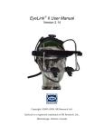
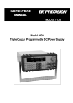
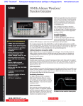
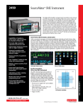
DC POWER
SUPPLY GUIDE
Keithley 2230-30-1
Department of
Electrical & Computer
Engineering
Keithley 2230-30-1 DC Power Supply Guide v1.0
Portland State University
1 – Introduction
This guide provides instructions for operating the Keithley 2230-30-1 DC power supply. The unit outputs
DC voltage and current to supply external electrical circuits with power.
Features:
•
Triple isolated DC output channels. Each is independently adjustable.
o
CH1, CH2 : 0 to 30 V, 0 to 1.5 A
o
CH3
: 0 to 6 V, 0 to 5 A
•
Overvoltage protection
•
Four-digit voltage and current displays
•
Push-button controls, numeric keypad, multipurpose knob
•
Double voltage and double current modes
•
Setup memory
•
Programmable
1
Keithley 2230-30-1 DC Power Supply Guide v1.0
Portland State University
2 – Instrument Front Panel
Arrow keys &
Enter button
Readout display
Readings or
settings
Top: voltage
Bot: current
Multipurpose
knob
Channel
select
buttons
Power
button
V-Set, I-Set,
Menu (LOCAL),
OUTPUT On/Off
function buttons
Keypad
Save, Recall
function buttons
CH1, CH2, CH3
output
connectors
Figure 1: Keithley 2230-30-1 front panel
Copyright © Keithley Instruments, Inc.
Power button
This switch turns the entire power supply either on or off.
CH1, CH2, CH3 output connectors
The power supply has three sets of output connectors – one for each output channel. Each set consists
of positive (+) and negative (-) terminal posts.
2
Keithley 2230-30-1 DC Power Supply Guide v1.0
Portland State University
Readout display
A two line alphanumeric readout shows the state of the output channels CH1, CH2, and CH3. The top
row displays the voltage (in volts), while the bottom row shows the current (in amperes).
Underline Cursor
Voltage
Current
Figure 2: Sample readout (output off, CH1 selected)
•
If the outputs are disabled (off), then one row displays the <OFF> message.
•
If the outputs are enabled (on), the power supply senses the output values. The readout shows the
measured output voltage and the measured load current for each channel, along with a CV or CC
message to indicate if the channel is operating in constant voltage or constant current mode.
•
If a voltage or current limit is being adjusted, the readout temporarily displays the new value, which
blinks to indicate input mode. Once entered, the readout reverts to showing the measured value.
•
An underline cursor highlights the channel that is selected for adjustment.
•
If the settings menu is accessed, the readout shows the existing values and options.
Channel select buttons (CH1, CH2, CH3)
Press one of these buttons to select an output channel for adjustment, such as changing the voltage
limit or current limit. The selected channel is highlighted by an underline cursor on the readout.
Keypad
Use the keypad to enter numeric values for the voltage or current limits of the selected output channel.
Keys for the digits 0 through 9 and the decimal point are available.
Enter key
•
After inputting a numeric value, press the Enter key to complete entry.
•
For Menu, Save, or Recall, push Enter to select an item.
Esc key
Use Esc to cancel a pending operation or to exit a menu.
3
Keithley 2230-30-1 DC Power Supply Guide v1.0
Portland State University
Arrow keys
•
For adjusting a numeric value, the left and right arrows move the cursor to individual digits within
the value. The up arrow increments the selected digit, while the down arrow decrements it.
•
In Menu mode, the up and down arrows scroll through the list of available menu items.
Multipurpose knob
•
For adjusting a numeric value, rotating the knob clockwise increments the value, while rotating the
knob counter-clockwise decrements it.
•
In Menu mode, the knob scrolls through the list of available menu items.
Note:
When incrementing or decrementing a numeric value using the up/down arrow keys or knob, the
currently underlined digit determines the step size.
Menu, OUTPUT On/Off function buttons
•
Menu
Accesses the settings menu. The up and down arrow keys scroll through the menu, while the Enter
key selects a menu item. The Esc key exits the menu.
•
OUTPUT On/Off
Enables or disables the DC outputs. Each press of the button toggles the output state. All three
outputs are turned on or off simultaneously, regardless of which channel is selected.
V-Set, I-Set function buttons
•
V-Set
Sets the desired output voltage.
•
I-Set
Sets the maximum output current.
Notes:
1. I-Set determines the maximum current that an attached load is allowed to draw. The actual load
current may be any value between zero and the current limit. If the load current exceeds the limit,
then the power supply switches to constant current mode.
2. V-Set and I-Set can be accessed at any time, regardless if the output is enabled or disabled.
3. Voltage and current limits for all three outputs are stored in non-volatile memory, so the power
supply retains its last used settings even when it is turned off.
4
Keithley 2230-30-1 DC Power Supply Guide v1.0
Portland State University
Save, Recall function buttons
•
Save
Up to 30 setups can be saved to non-volatile memory. Each setup consists of the voltage limit,
current limit, and protection setting. When Save is pressed, this message appears on the readout:
“Save (1-30) X”, where X is a memory location from 1 to 30.
Use the keypad, up/down arrow keys, or knob to pick the desired location. Press Enter to complete
the save operation, or Esc to cancel.
•
Recall
Previously saved setups can be recalled from memory. A setup consists of the voltage limit, current
limit, and protection setting. Recalling a setup will overwrite the existing limit and protection values.
When Recall is pressed, this message appears on the readout:
“Recall (1-30) X”, where X is a memory location from 1 to 30.
Use the keypad, up/down arrow keys, or knob to pick the desired location. Press Enter to complete
the recall operation, or Esc to cancel.
5
Keithley 2230-30-1 DC Power Supply Guide v1.0
Portland State University
3 – General Operating Procedure
Note: The → symbol indicates a sequence of buttons to push.
For safe operation of the DC power supply, follow this procedure:
1. Turn off the power supply.
2. Configure the output terminals as required.
(See Appendix 1: Typical Output Terminal Connections)
3. Connect your circuit to the power supply’s output terminal posts.
4. Turn on the power supply, but do not enable the outputs yet.
5. For each output you intend to use
a. Select the channel. The underline cursor highlights the selected channel.
To select
Buttons to press
Channel 1
CH1
Channel 2
CH2
Channel 3
CH3
b. Set the desired voltage limit and current limit for the selected channel:
To set
Buttons to press
Voltage
V-Set → Numeric value → Enter
Current
I-Set → Numeric value → Enter
Note: Numeric value consists of digits (and decimal point, if needed) that are entered via
the keypad, arrow keys, or knob. Data entry is completed by pushing the Enter button.
6. Enable the outputs. The <OFF> message on the readout disappears.
Button to press
OUTPUT On/Off
7. Test your circuit.
8. Once you are done testing, disable the outputs. The <OFF> message reappears.
Button to press
OUTPUT On/Off
6
Keithley 2230-30-1 DC Power Supply Guide v1.0
Portland State University
Example:
Set the voltage of CH1 to 5 volts with a current limit of 1.25 amperes.
1. Select CH1:
CH1
2. Set the voltage limit:
V-Set → 5 → Enter
3. Set the current limit:
I-Set → 1.25 → Enter
4 – Negative Voltages
To configure the 2230-30-1 to supply negative voltages, the output connectors need to be physically
wired in a specific way (See Appendix 1: Typical Output Terminal Connections). Regardless of the
expected polarities, all voltage and current limits are entered as positive numbers.
5 – Constant Voltage versus Constant Current Output
The power supply is designed to provide either a constant voltage (CV) or a constant current (CC) to an
attached load. The existing voltage limit, current limit, and load determine whether the power supply
attempts to keep the voltage constant or the current constant. The 2230-30-1 automatically switches
between these operating modes.
Example:
Suppose CH2 is set to 3.3 volts with a current limit of 0.25 amperes.
As long as the load attached to CH2 does not use more than 0.25 A of current, the power supply will
keep the supplied voltage constant at 3.3 V. The “CV” message is shown on the CH2 readout.
However, if the load attempts to draw more than 0.25 A of current, the power supply will limit the
current to 0.25 A and allow the supplied voltage level to drop below 3.3 V. In this case, the “CC”
message is displayed.
7
Keithley 2230-30-1 DC Power Supply Guide v1.0
Portland State University
6 – Overvoltage Protection
A channel’s maximum allowed output voltage can be adjusted to protect sensitive test circuits from an
accidental overvoltage condition. When protection is on, a user cannot enter a voltage limit larger than
the defined maximum. Protection can be turned on or off individually for each channel.
Here is the setup procedure:
1. Press the Menu button.
2. Select the “Protection Settings” menu item and press Enter.
3. Select the “Max Volt Set” item and press Enter.
4. Select the “Max V CH1” (or CH2 or CH3) item and press Enter.
5. Select the “On” item and press Enter.
The display will change to show this:
MaxVoltage Set
MaxVolt = value V (where value is the existing maximum in volts)
6. Adjust the MaxVolt to the desired value.
7 – Resetting the Power Supply
The power supply’s settings can be restored to their factory default values by following these steps:
1. Press the Menu button.
2. Select the “Default Set” menu item and press Enter.
3. Select the “Yes” item and press Enter.
Note:
For all channels, the default output voltage and current are 1 V and 0.1 A, respectively, with overvoltage
protection disabled.
8
Keithley 2230-30-1 DC Power Supply Guide v1.0
Portland State University
Appendix 1 – Typical Output Terminal Connections
•
Although only channels 1 and 2 are shown in the drawings, all three outputs work similarly.
•
Although not displayed in the equivalent circuit drawings, all practical power supplies have an
internal source resistance Rs.
•
The curved connections can be made by using insulated wire.
Single output (isolated)
V1 +
Load 1
+
CH1
CH2
–
–
Equivalent
Circuit
V1
+
–
Load 1
V1
+
–
Load 1
Dual outputs (isolated)
V1 +
Load 1
+ V
2
CH1
CH2
–
–
Equivalent
Circuit
Load 2
V2
+
–
Load 2
The circuits are completely isolated from each other.
Figure 3: Connections for circuits requiring isolation
9
Keithley 2230-30-1 DC Power Supply Guide v1.0
Portland State University
Dual positive outputs (common)
V1 +
Load 1
+ V
2
CH1
CH2
–
–
Equivalent
Circuit
+V1
V1
Load 2
+
–
+V2
V2
Load 1
+
–
Load 2
Common reference
Dual negative outputs (common)
Common reference
V1 +
Load 1
+ V2
CH1
CH2
–
–
Equivalent
Circuit
V1
Load 2
+
–
V2
Load 1
+
–
Load 2
−V2
−V1
Negative & positive outputs (common)
V1 +
Load 1
V1
+ V
2
CH1
CH2
–
–
+V1
+
–
Load 1
Equivalent
Circuit
Common
reference
Load 2
V2
+
–
Load 2
−V2
Figure 4: Connections for circuits requiring a common ground reference
VSS is the op-amp
supply voltage.
Vin
R2
R2
VSS +
+VSS
R1
−
+
Vout
+ V
SS
Vin
R1
−
Connection
CH1
−VSS
–
CH2
–
Common
reference
+
+VSS
−VSS
Figure 5: Example of inverting operational amplifier with bipolar power supply
10
Vout
Keithley 2230-30-1 DC Power Supply Guide v1.0
Portland State University
Appendix 2 – Technical Specifications
Table 1: Manufacturer’s specifications for 2230-30-1 model
DC Output Rating
Load Regulation
Line Regulation
Ripple and Noise
Setting
Resolution
Setting Accuracy
Meter Resolution
Meter Accuracy
Output Channel 1
Output Channel 2
Output Channel 3
Voltage
0 to 30 V
0 to 30 V
0 to 6 V
Current
0 to 1.5 A
0 to 1.5 A
0 to 5 A
Voltage
< 0.01% + 3 mV
< 0.01% + 3 mV
< 0.01% + 3 mV
Current
< 0.01% + 3 mA
< 0.01% + 3 mA
< 0.01% + 3 mA
Voltage
< 0.01% + 3 mV
< 0.01% + 3 mV
< 0.01% + 3 mV
Current
< 0.1% + 3 mA
< 0.1% + 3 mA
< 0.1% + 3 mA
Voltage
< 1 mV rms
< 3 mV p-p
< 1 mV rms
< 3 mV p-p
< 1 mV rms
< 3 mV p-p
Current
< 5 mA rms
< 5 mA rms
< 6 mA rms
Voltage
1 mV
1 mV
1 mV
Current
1 mA
1 mA
1 mA
Voltage
±0.03% + 10 mV
±0.03% + 10 mV
±0.03% + 10 mV
Current
±0.1% + 5 mA
±0.1% + 5 mA
±0.1% + 5 mA
Voltage
1 mV
1 mV
1 mV
Current
1 mA
1 mA
1 mA
Voltage
±0.03% + 10 mV
±0.03% + 10 mV
±0.03% + 10 mV
Current
±0.1% + 5 mA
±0.1% + 5 mA
±0.1% + 5 mA
11
Keithley 2230-30-1 DC Power Supply Guide v1.0
Portland State University
Appendix 3 – References
[1]
Models 2220 and 2230 Multi-Channel Programmable DC Power Supplies Data Sheet,
Keithley Instruments, Inc.
[2]
Series 2200 Multichannel Programmable DC Power Supplies User Manual,
Keithley Instruments, Inc.
12