1
INSTRUCTION
MANUAL
MODEL 9130
Model 9130
Triple Output Programmable DC Power Supply
Safety information
Please review the following safety precautions before operating our equipment.
General information
The following safety precautions should be observed before using this product and any associated
instrumentations.
This product is intended for use by qualified personnel who recognize shock hazards and are familiar
with the safety precautions required to avoid possible injury. Read and follow all installation, operation,
and maintenance information carefully before using the product. Refer to this manual for complete
product specifications.
If the product is used in a manner not specified, the protection provided by the product may be
impaired.
Before performing any maintenance, disconnect the line cord and all test cables.
Protection from electric shock
Operators of this instrument must be protected from electric shock at all times. The responsible body
must ensure that operators are prevented access and/or insulated from every connection point. In
some cases, connections must be exposed to potential human contact.
Under these circumstances personnel must be trained to protect themselves from the risk of electric
shock. If the circuit is capable of operating at or above 1000 volts, no conductive part of the circuit may
be exposed.
Definition of users
Responsible body is the individual or group responsible for the use and maintenance of equipment is
operated within its specifications and operating limits, and for ensuring that operators are adequately
trained.
This product should only be used as intended. Users must be trained in electrical safety procedures
and proper use of the instrument. Users must be protected from electric shock and contact with
hazardous live circuits.
Service is only to be performed by qualified service personnel.
Safety symbols and terms
Connect it to safety earth ground using the wire recommended in the user manual.
The symbol on an instrument indicates that the user should refer to the operating
instructions located in the manual.
Complies with the essential requirements of the European directives.
Certification
We certify that this product met its published specifications at time of shipment from the factory.
2
TABLE OF CONTENTS
1. INTRODUCTION ......................................................................................................................... 5
2. QUICK START .............................................................................................................................. 6
2.1 Front & Rear Panel ........................................................................................................................ 6
2.2 Preliminary Checkout ..................................................................................................................... 7
3. SPECIFICATIONS ...................................................................................................................... 12
3.1 Specifications ............................................................................................................................... 12
3.2 Supplemental Characteristics ...................................................................................................... 13
4. FRONT-PANEL OPERATION .................................................................................................... 14
4.1 Front-panel Operation Overview .................................................................................................. 14
4.2 Panel Description ......................................................................................................................... 15
4.3 VFD Description and Wiring Diagram .......................................................................................... 15
4.4 Menu Descriptions ....................................................................................................................... 16
4.5 Panel Operation ........................................................................................................................... 17
4.6 Menu Function.............................................................................................................................. 19
5. REMOTE OPERATION .............................................................................................................. 24
5.1 Communication cable................................................................................................................... 24
5.2 Communication between Power Supply and PC ......................................................................... 25
5.3 SCPI Command Overview ........................................................................................................... 26
5.3.1 Common IEEE488.2 commands.................................................................................................................... 26
5.3.2 Essential SCPI Commands ............................................................................................................................ 26
5.3.3 Nonstandard SCPI Commands ...................................................................................................................... 27
5.3.4 Simultaneous Control SCPI Commands (For firmware version 1.66 or above only) .................................... 28
5.4 SCPI Command Description ........................................................................................................ 30
5.4.1 SCPI Condition Register................................................................................................................................ 30
5.4.2 SCPI Command Description.......................................................................................................................... 32
6. PV9130 SOFTWARE GUIDE ..................................................................................................... 40
6.1 Introduction................................................................................................................................... 40
6.2 Installation .................................................................................................................................... 40
6.3 PV9130 basics ............................................................................................................................. 40
6.3.1 Save and Open ............................................................................................................................................... 42
6.3.2 Chart Description ........................................................................................................................................... 42
6.3.3 Status bar ....................................................................................................................................................... 43
6.4 Operation ...................................................................................................................................... 43
6.4.1 Configure the system ..................................................................................................................................... 43
6.4.2 Setting Voltage and Current ........................................................................................................................... 44
3
6.5 Test sequence generation ......................................................................................................... 44
6.5.1 Quickset ......................................................................................................................................................... 44
6.5.2 Program ......................................................................................................................................................... 45
6.5.2 Go/NG ........................................................................................................................................................... 45
4
1. Introduction
Description
The 9130 is a fully programmable triple Output DC Power Supply delivering 0-30V/0-3A on 2
outputs and 0-5V/0-3A on 1 output.
Each output is fully floating and outputs can be adjusted
independently or connected in series or parallel to produce higher voltages or currents.
The front
panel keys and the control knob provide a convenient means to adjust the voltage and current of a
selected output; enable or disable parallel or series tracking mode; store and recall operating states
or enable/disable individual outputs. The 9130 is ideally suited for applications in Electronic Test,
Production and Service, where multiple independent DC supplies are required and bench space is
at a premium.
Key Features
3 independent, fully programmable and electrically isolated outputs
Series or parallel operation
Display Voltage and Current for of all 3 channels simultaneously
Over Current (OCP) and Over Temperature (OHT) protection
Very compact foot print ( 2U x 1/2)
Bright and easy to read display (VFD technology)
High resolution, accuracy and stability
Output on/off control
Low ripple and low noise
SCPI compatible command set, communicate via USB or RS232 port
Application Software for front panel emulation and simple test sequence generation
50 memory locations for instrument state storage & recall
Convenient data entry via knob or numerical key pad
Rack mount kit available
5
2. Quick Start
This chapter will help you getting acquainted with the front panel operation of this power supply.
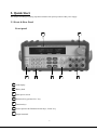
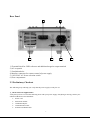
2.1 Front & Rear Panel
Front panel
2
1
3
4
5
1
VFD display
2
Rotary knob
3
Main power switch
4
Numerical key pad and “Esc” key
5
Function keys
6
Cursor position & Channel Selection keys, “Enter” key
7
Output terminals
6
6
7
Rear Panel
2
1
4
3
5
6
1) Terminal block for GND reference and additional negative output terminal
2) AC receptacle
3) Ventilation holes
4) Interface connector for remote control of power supply
5) 110V/220V AC Power selection switch
6) Fuse compartment
2.2 Preliminary Checkout
The following steps will help you verify that the power supply is ready for use.
1.Check the list of supplied items
Verify that you have received the following items with your power supply. If anything is missing, contact your
authorized B+K Precision distributor.
•
•
•
•
•
Power cord
Instruction manual
Calibration Report
Communication cable
Software installation disk
7
2.Connect the power cord and turn on the power supply
When you turn on the power supply, the front-panel display will light up briefly while the power supply
performs its power-on self-test. All the VFD annunciators will turn on at once. Check for any missing display
segments. In the event that there is no response when you turn on the power supply, refer to section 5 of this
chapter for additional information.
3. System Checkout
At power up, the instrument will automatically perform a self test routine. During this time, the following
should be displayed:
System Test, Please wait!
followed by
0.000V
<OFF>
0.000V 0.000V
<OFF> <OFF>
Or:
10.000V 11.000V 3.000V
2.000A 3.000A 3.000A
Note: The first row is the output voltage for channels 1 – 3. The second row will display the on/off state or the
output current of each channel.
In case the self test routine is not successful, you may see one of the following:
If the EEPROM is damaged, the VFD will display the following:
EEPROM Error
If the last operation data which should be stored in the EEPROM was lost you should see
Data Check Error
If the latest data about off-time in EEPROM was lost, the VFD will display
Load Off Time Fail
If the calibration data stored in the EEPROM was lost, the VFD will display
CH X Lost Calibration...
8
Note: “X” denotes the channel for which calibration data was lost.
If the calibration data in the EEPROM is corrupted or the factory calibration values are lost, the VFD will display
the following:
Lost Factory Calibration
Note: You will see a “?” on the VFD, in case of any errors are encountered during the self
test routine.
4.Output Verification
The following procedures verify that the power supply outputs the correct voltage and current levels and properly
responds to entries from the front panel.
• Voltage Output Checkout
The following steps verify basic voltage functions without load.
1) Turn on the power supply.
Turn on the outputs using the On/Off key
Note: Flashing voltage values indicates that the power supply is in “Set mode, ‘‘Set mode’’ means that
the VFD display shows the set values for voltage and current. In “meter mode” the display will
indicate the actual output voltage and current.
3) Check that the front-panel voltmeter properly responds to number key entries
Enter a different voltage value and wait a few seconds until the meter mode activates. Verify that the
actual output value voltage is identical to the set value. Also verify that the displayed current value is
close to zero.
4) Ensure that the voltage level can be adjusted from zero to the maximum rated value.
5) Verify channels 2 & 3 according to steps 1) – 4)
2)
• Current Output Current
The following steps check basic current functions with a short across the power supply’s output.
6) Turn on the power supply
7) Turn the output off
8)
9)
Press On/Off key to ensure that the outputs are off. (bottom row indicates “OFF”)
Connect the (+) and (-) output terminals of channel 1 with a short, insulated test lead. Use a wire size
sufficient to handle the maximum current.
Set the voltage value with 1V
10) Turn on the output using the On/Off key.
11) Adjust the current value
Enter a different current value, wait until the instrument is in meter mode, then make sure that the
displayed current value (actual output value) is the same as the set value.
12) Ensure that the current can be adjusted from zero to the maximum rated value.
13) Turn off the power supply and remove the short wire from the output terminals.
9
14) Verify channels 2 & 3 according to steps 1) – 8)
5.If the Power Supply Does Not Turn On
Use the following steps to help resolve problems you might encounter when turning on the instrument.
1). Verify that there is AC power applied to the power supply.
Verify that the power cord is firmly plugged into the power receptacle on the rear panel of the power supply.
Make sure the power outlet you are using is working properly and verify that the power supply is turned on.
2). Verify the power-line voltage setting.
Make sure the voltage selector switch is set according to the present line voltage (110VAC or 220VAC).
Change the voltage setting if it’s not correct.
3). Verify that the correct power-line fuse is installed.
Model
Fuse Description
9130
Fuse 3.15A T250V(220V AC)
Fuse 6.30A T250V(110V AC)
If the fuse is blown replace it according to the table above.
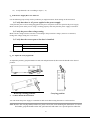
6.To Adjust the Carrying Handle
To adjust the position, grasp the handle on each side and pull outwards, then rotate the handle to the desired
position.
Bench-top viewing positions
7.
Carrying position
To Rack Mount the Instrument
You can mount the power supply in a standard 19-inch rack cabinet using the IT-E151 rack mount kit.
Note: Remove the carrying handle and the two plastic ears before rack-mounting the instrument. To remove
the handle, grasp the handle on the side, pull outwards and rotate it to a special position where the
10
arrow on the handle and the arrow on the plastic ears are in opposite directions. Now you can pull
the handle outwards. After removing the handle, you can remove the two plastic ears with a screw
driver.
11
3. Specifications
3.1 Specifications
Parameter
9130
Voltage
Current
LVP*
Voltage
Current
0~30V×2, 0~5V×1
0~3A×2, 0~3A×1
0~31V×2, 0~6V×1
≤0.01%+3mV
≤0.1%+3mA
Line Regulation
±(%of output+offset)
Voltage
≤0.01%+3mV
Current
≤0.1%+3mA
Programming
Resolution
Voltage
Current
Voltage
Current
1mV
1mA
1mV
1mA
Programming accuracy
(12 months)
±(%of output+offset)
Readback accuracy
(25 °C ± 5 °C)
±(%of output+offset)
Voltage
≤0.03%+10mV
Current
≤0.1%+5mA
Voltage
≤0.03%+10mV
Current
≤0.1%+5mA
Ripple & noise
Voltage
Transient Response
Time
Temperature coefficient
(0 °C ~ 40 °C)
±(%of output+offset)
Voltage
≤0.03%+10mV
Current
≤0.1%+5mA
Readback Temperature
Coefficient
±(%of output+offset)
Tracking Accuracy
Series Operation
Voltage
≤0.03%+10mV
Current
≤0.1%+5mA
Current
≤0.05%+10mA
Tracking Accuracy
Parallel Operation
Voltage
≤0.02%+5mV
Current
Time set
Resolution
≤0.1%+20mA
1s~999999s
1s
19.8 lbs, (9 kg)
214.5mm(W) × 88.2mm (H) × 354.6mm (D)
Output ratings
Load Regulation
±(%of output+offset)
Readback
Resolution
Output Timer
Weight
Dimensions
Ripple: ≤1mVrms/3mVp-p
Noise: ≤3mVrms
< 500 μs for CH1&2, < 200 μs for CH3
for output to recover to within 75 mV
following a change from 100 mA to 1 A
12
8.45in(W) x 3.8in(H) x 13.9in(D)
*)
LVP: Limit Voltage Protection. Limits the voltage than can be set either via the front panel or remote control command.
NOTE:
Specifications and information are subject to change without notice. Please visit www.bkprecision.com for the most
current product information.
3.2 Supplemental Characteristics
State Storage Memory
50 user-configurable stored states
Recommended Calibration Interval
1 year
AC Input Ratings (selectable via switch on the rear panel)
220AV±10%, 47~ 63Hz
110AV±10%, 47~ 63Hz
Maximum power consumption
Model
9130
Power
750VA
Cooling
Fan cooled
Operating Temperature
0 to 40 °C for max rated output
Storage Temperature
-20 to 70 °C for storage environment.
Environmental Conditions
Designed for indoor use in an installation category II, pollution degree 2 environment. Designed to operate at
maximum relative humidity of 95% and at altitudes of up to 2000 meters.
13
4. Front-panel Operation
So far we have covered the quick start chapter which briefly introduced the front panel operation and how to
check basic voltage and current functionality. This chapter describes in detail how to operate the instrument
manually via the front-panel keys.
4.1 Front-panel Operation Overview
The power supply is shipped from the factory ready for front-panel operation mode. At power-on, the power
supply will automatically enter the front-panel operation mode and the instrument can be controlled via the
font panel keys and knob.
The power supply enters remote mode as soon as a valid remote command is received via the
communication connector in the rear. Switching to remote mode does not impact the supply’s output
parameters. In remote mode, front-panel operation is disabled. If the power supply is in remote mode, and
the [LOCAL] key
●
is not disabled, you can revert to manual mode by pressing the [LOCAL] key
●
.
The power supply is in Meter mode when it is powered on. In this mode, the VFD will display the actual
voltage and current output value. If the user adjusts the knob while in this mode, the power supply will
automatically enter Set mode then revert back to meter mode and display the modified voltage and current
values.
The output of the power supply can be enabled/disabled from the front panel by pressing the
The VFD also displays operation states or error information. “
On/Off
key.
”means the power supply is in remote
mode. If an error occurred, ”?” will be displayed.
If the power supply is in Set mode, you can modify parameters using the knob. If the power supply is in
menu operation, the knob is used for menu selection. If the power supply is in the regular output mode you
can use the knob to set the voltage value.
If “?” is displayed on the VFD, please consult the submenu “error information” for more details (see chapter
4.4).
14
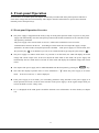
4.2 Panel Description
1
2
3
Esc
V-set
I-set
4
5
6
0
Save
Recall
7
8
9
●
Menu
On/Off
0~9
Use keys 1~3 to control the output state of the 3 channels。 Use keys 4~6 to set the
voltage and keys 7~9 to set the current value for each channel.
V-set
Set the voltage value
I-set
Set the current value
Save
Save the current setup of the power supply to internal memory
Recall
Recall the setup from internal memory
Menu
Set general parameters of the power supply
On/Off
Set the output state of the power supply
Up arrow key, select a menu or channel
Down arrow key, select a menu or a channel
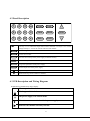
4.3 VFD Description and Wiring Diagram
Explanation of annunciators on the display
OFF
The output is off.
The key panel is locked.
The power supply is in remote mode.
?
Enter
There is some error or fault with the power supply.
Indicates the channel currently selected
15
4.4 Menu Descriptions
Press
Menu
to indicate operation mode. View the menu on the VFD, and use the
scroll through the complete menu listed below. Press
Enter
keys or the knob to
to enter the selected menu function, press
Esc
to return to the previous menu. A ”↑↓” symbol displayed on the left means that you are currently in the middle of
keys to select other menu parameter. If there is only”↑” displayed, you
a menu and you can now use the
are at the end of the currently active menu and you can only press the
key to select a different parameter.
Accordingly, ”↓” indicated that you can use the
key to select another parameter.
Symbols
enclose the currently selected menu.
Menu
Power Config...
Reset Config
System reset
Out State Set
“Remember” Output On/Off state before power off
Out Parameter Set
“Remember” parameters before power off
Key Sound Set
Knob Function Set
Enable/disable knob
Screen Brightness
Baud Rate Set
Set baud rate
Communication Parity
System Wait Time
determines duration of set mode
Local Address
Set communication address
Key Lock Set
Set password
Exit
System Set…
Out Series Set
Configure for series operation
Out Parallel Set
Configure for parallel operation
Max Voltage Set…
Set the max. voltage for each channel (LVP)
Set First Channel
Set Second Channel
Set Third Channel
Out Time Set…
Set output time for each channel
Set First Channel
Set Second Channel
Set Third Channel
Exit
Power Information…
Power Model
Display the power rating
16
…….
Power SN
display the serial number
Soft Version
Display the firmware version
Cal Information
Error Information
Exit
Exit Menu
4.5 Panel Operation
Channel Operation
When the power supply is in “METER” mode, you can select a channel using the arrow keys
.
OUT ON/OFF
Pressing On/Off toggles the output state of all 3 channels of the power supply. If the output state is ON,
press it, to turn the output state to OFF. While the output state is OFF, press On/Off and the power supply
output will turn ON.
To control channels individually, press one of the number keys
Key
1
and key
controls the output state of the first channel, key
3
2
1
,
2
3
corresponding to each channel.
controls the output state of the second channel
controls the output state of the third channel.
When the power supply is in remote mode, you can set the output state by sending SCPI command( OUTPut:
ON | OFF) The Output state operation doesn’t affect any other parameter.
Note: The On/Off
key controls the output state of all 3 channels simultaneously.
If you want to control the output state of individual channels, use the number keys 1-3.
Timer Operation
If you have set the output timer and the power supply is in “METER” mode, you can check the remaining time
by pressing
0
.
When the timer expires, the power supply will turn off the channel automatically.
Set Voltage
Solution 1: Press
V-set
, enter a numeric value (via key pad) then press
17
Enter
to confirm.
V-set
Solution 2: Press
, then use the arrow keys
to move the cursor to the desired position and
adjust the value with the knob. (Make sure the knob function is enabled in the systems menu,,
otherwise use solution 1). Press
Esc
or
Enter to return to meter mode.
(Otherwise the
cursor will remain visible indefinitely or until the system Wait time timer expires).
Solution 3: Press one of the keys 4-6, corresponding to the channel which you want to adjust (Press
5
adjust the first channel, press
to control the second channel and press
6
4
to
to control the
third channel).
4
For example, to set voltage for the first channel: Press
followed by
Enter .
using the knob. Press
Alternatively, press
Esc
Enter
or
, then enter a numerical value
to move the cursor adjust the voltage value
to escape and return to meter mode.
Set Current
Solution 1: Press
I-set
, enter a numeric value then press
Solution 2: Press
I-set
, the press
Enter
to confirm.
to move the cursor position and adjust the voltage value using the
knob. (Make sure the knob function is enabled in the systems menu,, otherwise use solution 1).
Esc
Press
or
Enter
to exit.
Solution 3: Press one of the number keys 7 – 9 corresponding to the channel for which you want to set the
current value. (Press key
key
9
to control the first channel,
8
for the second channel or press
to control the third channel). For example, if you want to set the current for the first
channel, press key
or press
7
7
, then enter a numeric value followed by the
Enter
to move the cursor and adjust the value with the knob. Press
key. Alternatively,
Esc
or
Enter
to escape and return to meter mode. (Otherwise the cursor will remain visible indefinitely or
until the system Wait time timer expires).
Save and Recall Operation
You can store up to 50 different operating states in memory locations 1 through 50. Each operating state
includes a constant voltage value, constant current value, maximum output voltage value and voltage step
value. Press
Save
followed by a number key to save the current operating state to non volatile memory.
18
Press
Recall
followed by a number 1 – 50 to recall operating state assigned to this location.
You can also use the SCPI command:*SAV、 *RCL to save and recall.
Over Temperature Protection
If the internal temperature of the power supply exceeds 80 °C, the instrument will protect itself by
automatically turning power OFF. When this happens you will hear a buzzer and the display will indicate the
following:
Over Temp
4.6 Menu Function
In menu operation, the
selection. The
Esc
keys or the knob can be used to select the menu.
Enter
is used to confirm a
key is used to exit the current menu
• Power Config
Reset Config
If you enter this menu and select “YES”, all parameters will be set to their default values.
Out State Set
This parameter sets the Output On/Off state at power up. If you select “Last Set”, the power supply will save
the output state prior to power down and revert to that state at power up. If you select “Off”, the output state is
always “OFF” when the power supply is turned on. The recommend setting is “OFF”.
If Out Parameter Set is set to “Default”, the output state of the power supply after power –up will always be off,
regardless of the settings of this parameter
Out Parameter Set
This parameter determines the state of the power supply after power up. If you select “Last Set”, the
power supply will automatically restore (“remember”) the last output parameters setting prior to power
down. If you select “default”, the default output parameter settings will be active after power up.
Recommend setting is “Last Set”.
Key Sound set
This parameter turns the beep sound for key presses “On” or “Off”.
Knob Function Set
This parameter enables (“On”) or disables (“Off”) the knob.
19
Baud Rate Set
This parameter configures the baud rate for serial communication. Possible values are 4800,9600,19200 or
38400. When operating the power supply in remote mode, make sure that you configure identical baud rate
settings for the power supply and the computer. The default setting is 9600.
Communication Parity
This parameter sets the parity bit for serial communication. Possible values are NONE, ODD and EVEN.
Default setting is NONE.
System Wait Time
This parameter determines how long the power supply will remain in set mode until it automatically reverts
back to meter mode or output mode The minimum is 4 seconds, and the maximum is 9999 seconds. Enter a
Enter or press
numerical value followed by
+
Enter
to set the wait-time. To disable the system
wait time function, set the wait time to 0 seconds. (In this case, the power supply will remain in set mode until
the ESC or ENTER key is pressed). Set mode is active when a cursor is visible.
Default setting is 0 seconds.
Note: the wait-time range is 4~9999S, if you set it with 1~3S, the wait-time will be 4S automatically.
Local Address
With this parameter, it is possible to address each instrument.
The address range is 0 to 30.
Key Lock Set
A password can be assigned (1 - 4 digits) to lock the function key operation. After setting the password, there
is a sign
On/Off
displayed on the VFD and all the function keys on the front panel will be locked except of the
key (if the knob is enabled,
keys can also can be used). You must enter the correct password to
unlock the keys. If you don’t want to lock the function keys, please set the password to 0 when entering
the >SET KEYLOCK function.
When the knob function is enabled:
You can press the
keys to move the cursor position, then enter a number and press
to select the cursor position and change the value using the password using the
the password. Or press
knob. Press +
Esc
or
Enter to set
Enter
to exit.
When the knob function is disabled:
Press number key+ Enter
to set the password or use the
• System Set
20
keys.
Out Series Set
This function configures the instrument for series operation of 2 channels. “None” means that each channel
operates independently (power supply not in series mode). “1+2” means that channel 1 and channel 2 operate
in series, 1+3 means that channel 1 and channel 3 operate in series.
Note: Channels 2 and 3 can NOT be configured for series operation.
Connection diagram example: Channels 1 and 2 connected in series
+
Load
Out Parallel Set
This function configures the instrument for parallel operation. “None” means that each channel operates
independently. “1+2” means that channel 1 and channel 2 operate in parallel, “1+3” and 2+3 means that
channels 1 and 3 or channels 2 and 3 respectively operate in parallel. ALL indicates that all 3 channels
operate in parallel.
Note: The output state of all channels will automatically be set to OFF and the voltage value
will be 0V after configuring the instrument for series or parallel operation, therefore you have to
set the parameter again after reconfiguration.
21
Connection diagram example: Channels 1 and 2 connected in parallel
+
Load
Note: When configuring for series or parallel operation, the user must wire
the terminals to match the configuration. The power supply does not
automatically connect the appropriate terminals internally based on the
configuration selected.
MaxVolt Set (LVP)
The max voltage you set should be within the range of 0V to the maximum rated voltage. You can edit this
value using the
keys or via numerical key pad followed by
maximum rated voltage for each channel.
Enter . The default setting is the
Out Time Set
This parameter sets the output timer for each channel. The range is 1~999999 seconds. If you enable this
function, and the output state of all channels is on, the timer will start counting down immediately. Once the
timer expires (count down from set value to zero) the output of the assigned channel will turn off. To disable
the timer, set the output time to zero.( 0 seconds). Default setting is 0 Seconds.
22
• Power Information
The following menus provide information about the specific power supply unit.
Power Model: the model of power supply
For example: 30V, 3A*2CH 5V, 3A*1CH
Power SN: the serial number
For example: 001001156074001165
Soft Version: the version number of the power supply
For example: Soft Version=1.00
Cal Information: calibration information of the power supply (last calibration date)
For example: 2005-8-26 17:46:13
Error Information: error information of power supply
For example: 0, No Error
Exit Menu
Note: after the error information has been displayed, you can press
Esc
or
Enter
to exit.
Afterwards the error information will be cleared out although the error condition still exists. Consult
the table below for an explanation of error codes.
0
'No Error'
There is no error.
1
'Too Many Num Suf'
The number in the ROM is too many to deal with.
10
'No Command'
The command is invalid.
14
'Num Suf Invalid'
The subscript of the number is invalid.
16
'Invalid Number'
The number is invalid.
17
'Invalid Dims'
The data dimension is invalid.
20
'Param Overflow'
Parameter overflow.
30
'Error Para Units'
Parameter unit error.
40
'Error Para Type'
Parameter type error.
50
'Error Para Count'
Parameter count error.
60
'Unmatched Quote'
The sign quoted by parameter is unmatched.
65
'Unmatched Bracket'
The bracket doesn’t match the parameter.
70
'Invalid Command'
The command is invalid.
80
'No Entry'
Command entry can not be found.
90
'Too Many Dims'
Too many data dimension.
100
'Too Many Command'
Too many commands.
101
'Command Exec Err'
An error occurred during command execution.
110
'Error Rxd Parity'
120
'Error EEPROM'
There is error when checking the EEPROM.
121
'Error Config Data'
Configuration data error.
122
'Error Cal. Data'
Calibration data error.
123
'Error Factory Data'
Calibration data supplied by factory is error.
23
5. Remote Operation
The DB9 interface connector on the rear panel of the power supply can be connected to a RS-232 or USB
interface via the included adapter cable. This chapter describes how to use a computer to control the output of the
power supply.
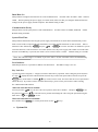
5.1 Communication cable
RS232 Communication cable IT-E131
The DB9 interface connector on the rear panel of the power supply provides a TTL voltage level interface. Use
the communication cable (IT-E131) to connect the DB9 interface connector of the power supply to the RS-232
interface connector of the computer
IT-E131 communication cable
Power
Load
supply
COMPUTER
IT
RS232
IT-E131 ISOLATED
COMMUNICATION CABLE
ISOLATION
INSTRUMENT
PC
PC
RX
TTL(5V)
TX
859666668889942311
Note: It is not possible to connect the DB9 connector of the power supply directly to a PC’s
RS232 or USB port.
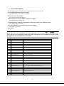
USB Communication cable IT-E132
The DB9 interface connector on the rear panel of the power supply provides a TTL voltage level interface. Use
the communication cable (IT-E132) to connect the DB9 interface connector of the power supply to the USB
interface connector of the computer.
IT-E131
communication
cable
IT-E132
communication
Power
Load
supply
COMPUTER
IT
RS232
IT-E131 ISOLATED
COMMUNICATION CABLE
ISOLATION
RX
TTL(5V)
TX
859666668889942311
INSTRUMENT
PC
PC
Note: Before you can use the USB communication cable, you must install the USB driver which
can be found on the included installation disk.
24
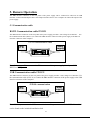
5.2 Communication between Power Supply and PC
Before putting the instrument into remote operation, make sure that the baud rate, parity bit and communication
address settings on the power supply and computer side are identical, otherwise communication will not be
possible.
1. Address Range is 0 to 30. Default setting is 0.
2. Baud rate: 4800,9600,19200 and 38400 are selectable, default setting is 9600
3. Parity and Data bits: None/8 bits (default setting)
Even/8 bits
Odd/8 bits
4. Stop bits:1 (fixed)
5. Start Bits: 1 (fixed)
Data Frame Format
Parity=None
Start
Bit
8 Data Bits
Stop
Bit
Parity=Odd,
Even
Start
Bit
8 Data Bits
Parity
Bit
Stop
Bit
End of String character is ’\n’ (0x0a)
DB9 Interface Details
The DB9 connector in the rear panel of the power supply provides a TTL level signal .It can be connected to a
standard PC interface via the IT-E131 or IT-E132 isolated communication cable.
Note: Setting of the address is optional. It is not required to communicate with the instrument. The
address can be set from the front panel and is stored in non volatile memory.
useful when connecting several instruments, e.g. via USB hub.
This feature is
In this scenario, Windows assigns
a virtual COM port to each device which is unknown prior to establishing communications with
the instrument (could be different each time).
In this case, the address will allow the user to
correlate each virtual COM port with the address assigned to each instrument.
25
5.3 SCPI Command Overview
5.3.1 Common IEEE488.2 commands
*CLS
*ESE
*ESE?
*ESR?
*IDN?
*OPC
*OPC?
*PSC
*PSC?
*RST
*SRE
*SRE?
*STB?
*SAV
*RCL
5.3.2 Essential SCPI Commands
SYSTem
:ERRor?
:VERSion?
:BEEPer[:IMMediate]
:ADDRess?
STATus
:QUEStionable
:ENABle <enable value>
:ENABle?
[:EVENt]?
:CONDition?
:OPERation
:ENABle <enable value>
:ENABle?
[:EVENt]?
:CONDition?
:INSTrumenu
[:EVENt]?
:ENABle <value>
:ENABle?
26
CONDition?
INSTrument
[:SELect] {FIRst|SECOnd|THIrd}
[:SELect]?
NSELect {1|2|3}
NSELect?
OUTPut
[:STATe] {0|1}
[:STATe]?
[SOURce:]
CURRent[:LEVel][:IMMediate][:AMPLitude] {<current>|MIN|MAX}
CURRent[:LEVel][:IMMediate][:AMPLitude]? {MIN|MAX}
VOLTage[:LEVel][:IMMediate][:AMPLitude] {<voltage>|MIN|MAX}
VOLTage[:LEVel][:IMMediate][:AMPLitude]? {MIN|MAX}
VOLTage:PROTection[:LEVel][:IMMediate][:AMPLitude]
VOLTage:PROTection[:LEVel][:IMMediate][:AMPLitude]?
5.3.3 Nonstandard SCPI Commands
CALibration
:SECure[:STATe] {ON|OFF,<quoted code>}
:SECure[:STATe]?
:VOLTage
LEVel <level>
[:DATA] <voltage value>
:CURRent
LEVel <level>
[:DATA] <current value>
:CODE
:SAVe
:INITital
OUTPut
:TIMer
:DATA <time>
:DATA?
SYSTem
:LOCal
:REMote
27
:RWLock
DISPlay:
[:WINDow][:STATe] {OFF|ON}
[:WINDow][:STATe]?
MEASure[:SCALer]
:CURRent[:DC]?
[:VOLTage][:DC]?
:POWer[:DC]?
5.3.4 Simultaneous Control SCPI Commands (For firmware version 1.66 or above only)
This section describes additional SCPI commands available for controlling parameters of all three channels
simultaneously without having to select each channel one at a time prior to setting their respective parameters.
NOTE: These commands are ONLY available for 9130 supplies with firmware version 1.66 or above. They
are not available for firmware versions below 1.66.
APPly:VOLTage[:LEVel][:IMMediate][:AMPLitude]
This command is used to set the 3 channels’ voltage at the same time.
Parameter type: three channels’ voltage setting value.
You can set the 1st ,2nd , and 3rd channels in one string.
Returned value: none.
Example: APP:VOLT 1,2,3 (set CH1, CH2, CH3 voltages as 1V,2V,3V respectively)
APPly:VOLTage[:LEVel][:IMMediate][:AMPLitude]?
This command is used to read out the 3 channels’ voltage setting value at the same time.
Parameter type:none
Returned value: The voltage setting value of the 3 channels.
Example: APP:VOLT?
APPly:CURRent[:LEVel][:IMMediate][:AMPLitude]
This command is used to set the 3 channels’ current at the same time.
Parameter type: three channels’ current setting value.
You can set the 1st ,2nd , and 3rd channels in one string.
Returned value: none.
Example: APP:CURR 1,2,3 (set CH1, CH2, CH3 current as 1A,2A,3A respectively)
28
APPly:CURRent[:LEVel][:IMMediate][:AMPLitude]?
This command is used to read out the 3 channels’ current setting value at the same time.
Parameter type: none
Returned value: The 3 channels’ current setting value.
Example: APP:CURR?
APPly:PROTvoltage[:LEVel][:IMMediate][:AMPLitude]
This command is used to set the max voltage of the 3 channels at the same time.
Parameter type: 3 channels’ max voltage setting value.
You can set the 1st ,2nd , and 3rd channels in one string.
Returned value: none
Example: APP:PROT 1,2,3 (set CH1, CH2, CH3 max. voltages as 1V,2V,3V respectively)
APPly:PROTvoltage[:LEVel][:IMMediate][:AMPLitude]?
This command is used to read out the 3 channels’ max voltage at the same time.
Parameter type: none
Returned value: The 3 channels’ max voltage value.
Example: APP:PROT?
APPly:OUT[:STATe]
This command is used to control the 3 channels’ ON/OFF status at the same time.
Parameter type: 0|1|ON|OFF
Returned value: none
Example: APP:OUT ON, OFF, ON
APP:OUT 1,0,1 (Set CH1, CH2, CH3 output to ON, OFF, ON respectively)
APPly:OUT[:STATe]?
This command is used to read out the 3 channels ON/OFF status at the same time.
Parameter type: none
Returned value: 0|1|ON|OFF
Example: APP:OUT?
MEASure[:SCALar]:VOLTage:ALL[:DC]?
This command is used to read out the measured output voltage value of the 3 channels simultaneously.
Parameter type: none
Returned value: 3 channels’ actual measured output voltage
Example: MEAS:VOLT:ALL?
MEASure[:SCALar]:CURRent:ALL[:DC]?
This command is used to read out the measured output current value of the 3 channels simultaneously.
Parameter type: none
Returned value: 3 channels’ actual measured output current
Example: MEAS:CURR:ALL?
29
MEASure[:SCALar]:POWer:ALL[:DC]?
This command is used to read out the measured output power value of the 3 channels simultaneously.
Parameter type: none
Returned value: 3 channels’ actual measured output power
Example: MEAS:POW:ALL?
5.4 SCPI Command Description
5.4.1 SCPI Condition Register
You can obtain the state of the power supply and read parameters from the operation register. The different states
of the power supply can be read from 7 condition registers. These registers are status byte register, standard event
register, quest condition register and operation status register. The status byte register stores the information of 3
other registers. The following table provides the details on each register’s meaning.
Operation status
sub register
Quest condition
register
Standard
register
bit
code
meaning
0
CAL
The power supply is calculating new calibration parameters.
1
UNR
The status of the power supply is unregulated.
2
CV
The power supply is in constant voltage condition.
3
CC
The power supply is in constant current condition.
4
RI
Not used
0
OV
Not used
1
OT
Over temperature
0
OPC
Operation of power supply is completed.
2
QYE
Query error. Data of output array is missing.
3
DDE
Device-dependent error. Data stored in register is missing or error occurs
in preliminary checkout.
4
EXE
Execution error. Command parameter overflows or the condition is not
right.
5
CME
Command error. Syntax or semantic error occurs when receiving
information.
7
PON
Power on. It is 1 when power supply is reset.
3
QUES
If a quest enable condition changes, QUES is 1.
5
ESB
If a standard event status enable register changes, ESB is 1.
6
MSS
7
OPER
If a operation event enable register changes, OPER is 1.
1
INST1
If the status of one operation status sub register changes, INST is 1
2
INST2
As above
3
INST3
As above
event
4
Status
register
byte
operation status
register
30
The Structure of the condition register is as followed:
condition
event
enable
condition
event
enable
condition
event
enable
CAL
CAL
CAL
CAL
CAL
CAL
CAL
CAL
CAL
UNR
UNR
UNR
UNR
UNR
UNR
UNR
UNR
UN
R
CV
CV
CV
CC
CC
CC
or
Operation status sub register(channel 1)
condition
event
CC
CC
CC
CV
CV
CV
Operation status sub register(channel 2)
or
CV
CV
CV
CC
CC
CC
Operation status sub register(channel 3)
enable
INST1
INST1
INST1
INST2
INST2
INST2
INST3
INST3
INST3
or
Operation status register
condition
event
enable
OPC
OPC
OPC
QYE
QYE
QYE
DDE
DDE
DDE
EXE
EXE
EXE
CME
CME
CME
PON
PON
event
or
PON
Standard event register
condition
enable
QUES
QUES
ESB
ESB
RQS
RQS
OPER
OPER
or
Status byte register
event
enable
OV
OV
OV
Lowest bit: 0
OT
OT
OT
First bit: 1
or
Note:
Second bit: 2
The bit array of each
Third bit: 3
register is as right
Forth bit: 4
table:
Fifth bit: 5
Sixth bit: 6
Highest bit: 7
Quest condition register
31
or
5.4.2 SCPI Command Description
Common IEEE488.2 Commands
*CLS
This command clears the following registers:
Standard event status register
Quest condition register
Operation status register
Operation status sub register
Status byte register
Error code
Command syntax: *CLS
Parameter: None
*ESE
This command sets the parameter of the standard event enable register. The value determines which bit
value of the standard event register is set to 1. The ESB bit in of the status byte register will change to 1 to
reflect the changes.
Command syntax: *ESE <NRf>
Parameter: 0~255
Reset value: Consult *PSC command
Example: *ESE 128
*ESR?
This command queries the standard event status register. After executing this command, the standard event
status register is reset. The bit definition of the standard event status register is identical to the standard
event status enable register
Query syntax: *ESR?
Return parameter: <NR1>
Example: *ESR?
*IDN?
This command reads information about the power supply. The return value contains 4 segments divided by a
comma.
Query syntax: *IDN?
Return parameter: <AARD>
segment
description
BK Precision
manufacturer
XXXX
model
XXXXXX
product serial number
32
VX. XX
software version number
For example: BK PRECISION, 9130, 000000000000111101,V1.66
*OPC
When all commands sent to the instrument prior to this command have been executed, OPC of the
standard event status register will be set to 1.
Command syntax: *OPC
Query syntax: *OPC ?
Example: *OPC
*PSC
This command controls if the power supply sends a query or not when it is reset.
1|ON:
When power supply is reset, operation event enable register, quest event enable register and
standard event status register are all reset.
0|OFF:
The data of operation event enable register, Quest event enable register and standard event
status enable register is stored in a nonvolatile register, and is recalled when power supply is reset.
Command syntax: *PSC
Parameter: 0|1|ON|OFF
Return parameter: data stored
Example: *PSC ON
*RST
This command resets the power supply to its default setting.
Command syntax: *RST
Example:
*RST
*SRE
This command can set the parameter of the status byte enable register. The value of this parameter determines
which bit value of the status byte register is 1 and the byte will enable RQS of status byte register is 1. The bit
definition of the status byte enable register is the same as the status byte register.
Command syntax: *SRE <parameter>
Parameter: 0~255
Reset value: consult command *PSC
Example: *SRE 110
*STB?
This command reads data from the status byte register. After executing this command, the status byte register
is reset.
Command syntax: *STB?
Return parameter: <NR1>
Example: *STB?
*SAV
This command saves the operating parameters of the power supply to non-volatile memory.
33
The
parameters include constant current, constant voltage, maximum voltage value and step voltage values.
Command syntax: *SAV
Parameter: 0~49
Example: *SAV 10
*RCL
This command recalls parameter saved previously (using the *SAV command).
Command syntax: *RCL
Parameter: 0~49
Example: *RCL 10
Essential SCPI Commands
SYSTem:ERRor
This command is used to obtain error information from the power supply.
Command syntax: SYSTem:ERRor?
Return parameter: please consult the error information table
Example: SYST:ERR?
SYSTem:VERSion
This command queries the software version.
Command syntax: SYSTem:VERSion?
Return parameter: software version
Example: SYST:VERS?
SYSTem:BEEPer
This command controls the buzzer
Command syntax: SYSTem:BEEPer[:IMMediate]
Example: SYST:BEEP
SYSTem:LOCal
This command can set the instrument to local (operate from front panel) mode
Command syntax: SYSTem:LOCal
Example: SYST:LOC
SYSTem:REMote
This command configures the power supply for remote control mode.
Command syntax: SYSTem:REMote
Example: SYST:REM
SYST:RWLock
This command also sets the instrument to remote control mode. When using this command, it is not
possible to press LOCAL key on the front panel to revert back to manual mode.
Command syntax: SYSTem:RWLock
34
Example: SYST:RWL
SYSTem:ADDRess
This command reads the communication address of the power supply.
Command syntax: SYSTem:ADDRess?
Example: SYST:ADDR?
STATus:QUEStionable:ENABle
This command sets the parameter of the quest event enable register. This parameter determines which bit of
the quest event register is set to 1. If a QUES condition changes, the QUES bit of status byte register will
be set to 1.
Command syntax: STATus:QUEStionable:ENABle <parameter>
Parameter: 0~255
Reset value: Consult PSC command
Example: STAT:QUES:ENAB 110
STATus:QUEStionable:ENABle?
This query returns a value which corresponds to the binary weighted sum of all bits enabled by
STAT:QUIES:ENAB command. After this command executed, quest event enable register is reset.
Command syntax: STATus:QUEStionable:ENABle?
Return parameter: <NR1>
Example : STAT:QUES:ENAB?
STATus:QUEStionable?
This command reads parameters from the quest event register. After this command executed, quest event
register is reset.
Command syntax: STATus:QUEStionable[:EVENt]?
Return parameter: <NR1>
Example: STAT:QUES?
STATus:QUEStionable:CONDition?
This command queries the parameter of the quest condition register. When a bit value of the quest condition
parameter changes, the corresponding bit value in the quest event register will be set to 1.
Command syntax:: STATus:QUEStionable:CONDition?
Return parameter: <NR1>
Example: STAT:QUES:COND?
STATus:OPERation ENABle
This command sets the parameter of the operation event enable register. The parameter determines which bit
value of quest event register is set to 1. If a OPER condition changes, the OPER bit of the status byte
register will be set to 1.
Command syntax: STATus: OPERation:ENABle
35
Parameter: 0~255
Reset value: consult PSC command
Example:
STAT:OPER:ENAB 110
STATus:OPERation:ENABle?
This command queries parameters from the operation enable register
Command syntax: STATus:OPERation:ENABle?
Return parameter: <parameter of operation enable register>
Example: STAT:OPER:ENAB?
STATus:OPERation?
This command queries the operation condition register. After this command executed, the operation
condition is reset.
Command syntax: STATus:OPERation[:EVENt]?
Return parameter: <parameter of operation event register>
Example: STAT:OPER?
STATus:OPERation:INSTrument?
This command queries the operation event sub register. After this command executed, the operation event
sub register is reset.
Note: this command is only valid for current channel.
Command syntax: STATus:OPERation:INSTrument[:EVENt]?
Return parameter: <parameter of operation event sub register>
Example: STAT:OPER:INST?
STATus:OPERation:INSTrument:ENABle
This command sets the parameter of operation event enable sub register. Setting parameter can determine
which bit value of operation event enable sub register is 1 and the bit will enable OPER of status byte
register is 1.
Note: this command is only valid for current channel.
Command syntax: STATus:OPERation:INSTrument:ENABle <value>
Parameter: 0~255
Reset value: consult PSC command
Example: STAT:OPER:INST:ENAB 110
STATus:OPERation:INSTrument:ENABle?
This command queries the parameter of the operation event enable sub register. After this command
executed, operation event enable sub register is reset.
Note: this command is only valid for the currently active channel.
Command syntax: STATus:OPERation:INSTrument:ENABle?
Return value: <parameter of operation event enable register>
Example: STAT:OPER:INST:ENAB?
36
STATus:OPERation:INSTrument:CONDition?
This command queries parameters from operation condition sub register. After this command is executed,
the operation condition sub register is reset.
Note: this command is only valid for current channel.
Command syntax: STATus:OPERation:INSTrument:CONDition?
Return parameter: <parameter of operation condition register>
Example: STAT:OPER:INST:COND?
INSTrument[SELect]
This command can be used to select the channel.
Command syntax: INSTrument[:SELect]
Parameter: FIRst|SECOnd|THIrd
Reset value: FIRst
Example: INST SECO
INSTrument[:SELect]?
This command returns the number of the selected channel
Command syntax: INSTrument[:SELect]?
Return parameter: FIRst|SECOnd|THIrd
Example: INST?
INSTrument:NSELect
This command is similar to the command “INSTrument[SELect]”, the only difference is that this command
uses numbers to denote the channel.
Command syntax: INSTrument:NSELect
Parameter: 1~3
Reset value: 1
Example: INST:NSEL?
OUTPut[:STATe]
This command sets the output state for the current channel to ON or OFF
Command syntax: OUTPut[:STATe] <parameter>
Parameter: 1(ON)|0(OFF)
Example: OUTP 1
OUTPut[:STATe]?
This command queries the output state of the current channel is ON or OFF
Command syntax: OUTPut[:STATe]?
Return parameter: 0|1
Example: OUTP?
OUTPut:TIMer:DATA
This command sets the time of the output-timer for the current channel.
Command syntax: OUTPut:TIMer:DATA <parameter>
37
Parameter: 0~999999S (if you set 0S,the output-timer will be disabled.)
Reset value: It is concerned about the parameter you set in the menu.
Example: OUTPut:TIMer:DATA 100
OUTPut:TIMer:DATA?
This command queries the time of the output-timer for the current channel.
Command syntax: OUTPut:TIMer:DATA?
Return parameter: 0~999999
Unit: S
Example: OUTP:TIM:DATA?
[SOURce:]CURRent[:LEVel][:IMMediate][:AMPLitude]
This command sets the current value of the power supply.
Command syntax: [SOURce:]CURRent[:LEVel][:IMMediate][:AMPLitude] <parameter>
Parameter: MIN|MAX|MIN TO MAX
Unit: A mA uA
Reset value: It is concerned about the parameter you set in the menu.
*RST value: MAX
Example: CURR 2A
[SOURce:]CURRent[:LEVel][:IMMediate][:AMPLitude]?
This command checks the current value of the power supply.
Command syntax: [SOURce:]CURRent[:LEVel][:IMMediate][:AMPLitude]? <parameter>
Parameter: MIN | MAX |None
Return parameter: MIN TO MAX
Unit: A
Example: CURR?
[SOURce:]VOLTage[:LEVel][:IMMediate][:AMPLitude]
This command sets the voltage value of the power supply.
Command syntax: [SOURce:]VOLTage[:LEVel][:IMMediate][:AMPLitude]
Parameter: MIN|MAX|MIN TO MAX
Parameter: V mV uV kV
Reset value: IN TO MAX|MIN|MAX
*RST value: MIN
Example: VOLT 10V
[SOURce:]VOLTage[:LEVel][:IMMediate][:AMPLitude]?
This command reads the voltage value of the power supply.
Command syntax: [SOURce:]VOLTage[:LEVel][:IMMediate][:AMPLitude]? <parameter>
Parameter: MIN|MAX|None
Reset value: MIN TO MAX
Unit: V
Example: VOLT?
38
[SOURce:]VOLTage:PROTection[:LEVel][:IMMediate][:AMPLitude]
This command sets the max. voltage for the current channel.
Command syntax: [SOURce:]VOLTage:PROTection[:LEVel][:IMMediate][:AMPLitude] <parameter>
Parameter: IN TO MAX|MIN|MAX
Unit: V mV kV uV
Reset value: It is concerned about the parameter you set in the menu.
*RST value: MAX
Example: VOLT:PROT 20V
MEASure[:SCALer]:CURRent[:DC]?
This command reads the actual output current of the power supply.
Command syntax: MEASure[:SCALer]:CURRent[:DC]?
Return parameter: The actual output current
Unit: A
Example: MEAS:CURR?
MEAS[:SCALer][:VOLTage][:DC]?
This command reads the actual output voltage value.
Command syntax: MEAS[:SCALer][:VOLTage][:DC]?
Return parameter: The actual output voltage
Unit: V
Example: MEAS?
MEASure[:SCALer]:POWer[:DC]?
This command reads the actual output power value.
Command syntax: MEASure[:SCALer]:POWer[:DC]?
Return parameter: The actual output power
Unit: W
Example: MEAS:POW?
DISPlay[:WINDow][:STATe]
This command turns the VFD display on/off.
Command syntax: DISPlay[:WINDow][:STATe] <parameter>
Parameter: 0(OFF)|1(ON)
Reset value: 1(ON)
*RST value: 1(ON)
Example: DISP 1
DISPlay[:WINDow][:STATe]?
This command checks the state of the display.
Return parameter: 1(ON)|0(OFF)
Example: DISP?
39
6. PV9130 Software Guide
6.1 Introduction
PV9130 is a software application for the 9130 Triple Output Programmable DC Power Supply. To use this
software communication you need either communication adapter cable IT-E131 or IT-E132. This application
software supports all the functionality available through the front panel. Additionally you can generate and
execute simple test sequences.
6.2 Installation
1.Requirements for computer
Pentium processor-based personal computer
Windows 98/2000/NT/XP/VISTA
2. Installation
Insert the included CD into the CD drive, locate PV9130 and install the software according to the onscreen
instructions.
6.3 PV9130 basics
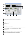
After launching software PV9130, you should see following screen:
40
1
11
2
10
3
4
5
6
1
7
8
9
Configure the software operating parameters and serial communication parameters.
2
Voltage chart
3
Voltage and current displayed for all 3 channels
4
Set the voltage value
5
Set operation mode: PC Control or Panel Control
6
Set the output state: Output On/Output Off
7
“Local Enable” allows the user to use the front panel keys while the instrument is in remote control mode.
When “Local Disable” is active, the front panel keys of the instrument are disabled.
8
Set the current value
9
Status bar: Displays the power supply model, communication status and operation status.
10
Set voltage and current value quickly and conveniently via predefined hotkeys
11
Current chart
41
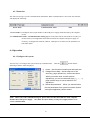
6.3.1 Save and Open
Save the program, Quick Set, voltage sweep and GO/NG settings to a PAR file.
Open the program, Quick Set, voltage sweep and GO/NG settings stored in a PAR file.
6.3.2 Chart Description
The voltage and current chart can help you to analyze voltage and current changes more easily.
If you want to observe the voltage and current change curve after you have set the voltage and current value for
one channel, please make sure that the channel’s output state is on
. If you want to observe the
voltage and current curve at the same time, you need to set voltage and current value for each channel one by one,
and turn the channel’s output state on.
Note: After you have set voltage/current values or the output state for one channel and you want to set
parameters for another channel, you can select the channel you want to configure directly via the
tabs
(blue means the channel is selected). The other channel’s state isn’t
affected.
42
6.3.3 Status bar
The status bar will give you the communication information. When communication is successful, the status bar
will display the following:
Power mode
Communication status
Time
1) Power mode: it will display the real part number of the field power supply which detected by the computer.
(9130)
2) Communication status: If Communication waiting appears in the status bar for more than 10 seconds, you
need to check your configuration and connection between computer and power supply. If
necessary, reconfigure the baud rate, address, COM port etc to make sure the parameters on
both sides match.
6.4 Operation
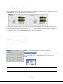
6.4.1 Configure the system
The first step is to configure the system and set up communication.
Click the
button and the
following windows will be displayed:
1) Comm: Set the communication port and baud rate
2) Voltage/Current Step: Set the step size of the
arrow key, page up/down key, and mouse-wheel.
When you set the value via knob (coarse
adjustment), you can use the arrow keys ( ↑,↓, ←, →),
page up/down keys or mouse wheel for fine
adjustment.
3) Reload last parameter: When you check this box,
the last parameters from a previous session (before
closing this application) will be loaded.
Note:When you set the communication port, please make sure that the baud rate of the computer
matches that of the power supply. Also make sure that “Parity” in the power supply menu is set to
“None” (default value).
43
6.4.2 Setting Voltage and Current
Before setting voltage/current values, you need to select a channel. If you want to set voltage and current for
several channels, you can do so by setting one channel at a time
Use the mouse to click on the rotary knob and move the mouse to change the value. You also can use the mouse
wheel, or Page Up/Down keys and arrow keys (↑, ↓,←, →) from the keyboard for fine adjustment of voltage or
current values.. The setup value will be displayed on the second line indicator.
6.5 Test sequence generation
6.5.1 Quickset
Hot Keys
Hotkey: Right-click each Hotkey Button, it will display
, Click on it, it will display as follows, change
the voltage/current value as you desired, then click “OK” button to
confirm.
Note: The voltage/current value you set should not exceed the max voltage /current value.
44
Voltage Sweep
Before this operation, please select the channel you need:
.
Enter parameters StartValue, StopValue, voltageStep and Delay. Press “View Scan Panel”, then “Run” to sweep
from the Start to the Stop value once or “Step” to manually execute each test step.
Refer to the on line help for more details
6.5.2 Program
Write a simple sequence of test steps using this tool.
Before programming, please select the channel:
.
Right-click in the Program area. The program tools (AppendLine, Insert Line, DeleteLine) will appear. Use
these tools to define each test step and add new test steps.
Click on “View Test Control Panel” to execute your test sequence. Select “Run” to execute the sequence in a
loop, “Once” or Custom (define the number of loops)
For more details, refer to the on-line help.
6.5.2 Go/NG
This tool allows you to write a simple test sequence including min/max values.
pass fail verdict and an optional test report.
Before test, please select the channel:
The test program generates a
.
Right-click in the Program area. The program tools (AppendLine, Insert Line, DeleteLine) will appear. Use
these tools to define each test step and add new test steps.
Click on “View Test Control Panel” to execute your test sequence. Select “Run” to execute the sequence in a
loop, “Once” or Custom (define the number of loops)
For more details, refer to the on-line help.
45
[left intentionally blank]
46
Service Information
Warranty Service: Please return the product in the original packaging with proof of purchase to the
address below. Clearly state in writing the performance problem and return any leads, probes, connectors
and accessories that you are using with the device.
Non-Warranty Service: Return the product in the original packaging to the address below. Clearly state in
writing the performance problem and return any leads, probes, connectors and accessories that you are
using with the device. Customers not on open account must include payment in the form of a money order
or credit card. For the most current repair charges please visit www.bkprecision.com and click on
“service/repair”.
Return all merchandise to B&K Precision Corp. with pre-paid shipping. The flat-rate repair charge for
Non-Warranty Service does not include return shipping. Return shipping to locations in North American is
included for Warranty Service. For overnight shipments and non-North American shipping fees please
contact B&K Precision Corp.
B&K Precision Corp.
22820 Savi Ranch Parkway
Yorba Linda, CA 92887
www.bkprecision.com
714-921-9095
Include with the returned instrument your complete return shipping address, contact name, phone
number and description of problem.
Limited Three-Year Warranty
B&K Precision Corp. warrants to the original purchaser that its products and the component parts thereof,
will be free from defects in workmanship and materials for a period of three years from date of purchase.
B&K Precision Corp. will, without charge, repair or replace, at its option, defective product or component
parts. Returned product must be accompanied by proof of the purchase date in the form of a sales receipt.
To obtain warranty coverage in the U.S.A., this product must be registered by completing a warranty
registration form on www.bkprecision.com within fifteen (15) days of purchase.
Exclusions: This warranty does not apply in the event of misuse or abuse of the product or as a result
of unauthorized alterations or repairs. The warranty is void if the serial number is altered, defaced or
removed.
B&K Precision Corp. shall not be liable for any consequential damages, including without limitation
damages resulting from loss of use. Some states do not allow limitations of incidental or consequential
damages. So the above limitation or exclusion may not apply to you.
This warranty gives you specific rights and you may have other rights, which vary from state-to-state.
B&K Precision Corp.
22820 Savi Ranch Parkway
Yorba Linda, CA 92887
www.bkprecision.com
714-921-9095
47
22820 Savi Ranch Parkway
Yorba Linda, CA 92887
www.bkprecision.com
© 2009 B&K Precision Corp.
V092711
Printed in China
48


![H5DA(M)IA [轉換].ai - Anly Electronics Co., Ltd.](http://vs1.manualzilla.com/store/data/005881219_1-4b829119a0226e59b0b94ecac6325c4d-150x150.png)

![H8DA(M)JA [轉換].ai - Anly Electronics Co., Ltd.](http://vs1.manualzilla.com/store/data/005792054_1-e40506c7505a129d0c559401a2fa00b1-150x150.png)