1
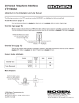
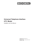
2
General description
This chapter provides a general description of the
product MVB Virtual Terminal and PCNode:
Properties of the Multifunction Vehicle Bus
Applications of the product MVB Virtual Terminal and
PCNode
Software and hardware of the product MVB Virtual
Terminal and PCNode
General description
Multifunction Vehicle Bus – overview
The Multifunction Vehicle Bus (MVB) is a serial communication
bus for railway vehicles. It connects programmable equipment
with each other and attaches directly to simple sensors and actuators. It is not intended for communication between vehicles – this is
the domain of the train bus.
The MVB is standardised by IEC, TC9, WG 22 in the standard Electric Traction Equipment - Train Communication Network, Parts 1 to 3.
Properties of the MVB
The environment of train vehicles is very hostile for electronic
equipment. Hence the MVB bears properties which are not needed
for buses in the computer environment.
Magnetic fields
Magnetic fields are omnipresent in train vehicles. Hence the bus
must operate securely in this environment.
Operating temperature
Train vehicles circulate all over the world. Hence the operating
temperature can be as low as in a Siberian winter or as high as
open sunshine in the Arabian desert.
Mechanical stability
Mechanical shocks are common to train vehicles. Both the cables
themselves and the connectors must be absolutely safe for these
situations. This applies also to the senors, actuators and controllers on the bus.
Media and topology
Copper lines are intended for short distances and optical fibres for
long distances. Using redundant lines allows modification of the
bus topology without interruption. With copper lines a power line
may be included to power the bus terminators and also devices on
the bus.
Signals
The MVB uses a media independent method of signalling with
Manchester encoding.
Bus management
Availability is increased, because mastership can be alternated
between two or more bus administrators. Mastership is transferred
from one bus master to another by a token frame.
Redundant layout
The MVB allows redundant layout with both twisted wire pairs
and with optical fibre. This increases availability. You can limit
redundancy to critical segments of the bus.
2-2
MVB Virtual Terminal and PCNode - User Manual and Reference
Multifunction Vehicle Bus – overview
Access modes
The MVB offers two access modes to the communications medium:
• In periodic access mode, a predefined sequence of addresses
are polled with a well-defined and deterministic period. This
mode is intended for the transmission of periodic data.
• In sporadic access mode, devices announce an event. This
mode is intended for transmission of message data. Sporadic
traffic uses the time between the fixed, periodic phases.
Summary of properties .
Property
Characteristics
Communications medium Copper: twisted wire
pair, biased RS 485
Optical fibres and active
star coupler
Topography
Bus
Star
Extension
30m for RS 485 segment 2000m
with 32 taps
Redundancy
Duplicated media: send on both, receive on one.
Redundant masters with rotation
Gross data rate
1.5 Mb/s
Response Time
Typical 4µs, maximum 43µs
Address space
4095 physical devices, 4095 logical ports, 8-bit station address for messages
Frame size (useful data)
16, 32, 64, 128 and 256 bits
Medium access control
Centralised master. Mastership transfer by token
passing for back-up masters
Bus management
background polling of devices, service messages,
bus configuration
Regular operation
Periodic polling for proc- Sporadic access for mesess data
sage data with arbitration
Application
Process variables
Logical link control
Broadcast of sourceSlave-to-slave datagrams
addressed process dat a
Remote procedure call
Applications of the MVB
Due to its special properties (see details on the following pages)
the MVB has many areas of application outside the domain of
train vehicles. For example, the MVB is best suited for controlling
high voltage switching bays or controlling power plants.
TN-AC-95/185
95-12-19
2-3
General description
Multifunction Vehicle Bus – details
This section provides background information for system engineers evaluating the capabilities of the Multifunction Vehicle Bus.
This section also provides the necessary details to understand the
various items used in the dialogs of Virtual Terminal.
For a recapitulation of bus communication in general see the
appendix chapter.
Bus medium
Topology of the MVB
The Multifunction Vehicle Bus is the standard data carrier in locomotives, coaches or groups of vehicles not separated during normal operation. It provides both the interconnection of programmable programmable equipment among themselves and the interconnection of programmable equipment with their sensors and actuators. MVB supports up to 4095 devices.
MVB physical layer
1) The
Multifunction Vehicle Bus uses three different media, which
all operate at a unified speed of 1.5Mb/s.
• an electrical medium for short distances (20m), for instance to
connect devices within racks and cabinets. This uses standard
RS 485 transceivers.
• an electrical medium for middle distances (up to 200m) using a
shielded, twisted wire pair and transformer coupling to provide galvanic separation,. This uses standard IEC 1158-2 transformers and transceivers.
• optical fibre for longer distances (up to 2000m) and critical
environments, such as locomotives.
While the electrical media preferable have a bus structure, the
optical medium usually has a star structure centred on an active or
passive star coupler. The optical medium can also be laid out as a
bus, if the number of devices is small enough to permit active or
passive optical taps.
Configurations
In closed train sets, the MVB may span several vehicles. Fibre
optics are not recommended for this purpose when the vehicles
are frequently coupled and uncoupled.
The Multifunction Vehicle Bus has no provision to support configurable vehicles, the device addresses are fixed.
1
[part 1 / p 40 ]
2-4
MVB Virtual Terminal and PCNode - User Manual and Reference
Multifunction Vehicle Bus – details
Signalling on the MVB
The data are encoded using a baseband Manchester code, which
combines into one signal the data, the clock and the frame synchronisation. A “1” is transmitted as a negative transition (active
to idle) in the middle of a bit cell, a “0” as a positive transition
(idle to active) 2).
Data
1 1 0 1 0 0 0 1 0 1 1 1 1 1 0 1
Clock
Frame
line active
Signal
line idle
useful frame data
9-bit delimiter
8-bit check sequence
end delimiter
The frame data is headed by a 9-bit frame delimiter and followed
an 8-bit check sequence.
Start delimiter
The start delimiter is used for synchronizing receivers and contains 3 Manchester code violations (transitions of 1.5 cell lengths)
to distinguish it from valid data bit sequences. Master frames and
slave frames have different delimiters to protect against synchronisation slips.
Check sequence
The check sequence is built over at most 64 data bits. It uses the
high-safety TC57 telecontrol algorithm to provide a Hamming distance of 6. The Manchester encoding is inherently robust since both
halves of a bit cell must be inverted to create a false bit. Taking
this encoding into account, the achieved Hamming distance is
even higher (around 8).
End delimite r
The frame is closed by an end delimiter to detect the end of a
frame. For the fibre optics and the RS 485 transmission this is simply returning the line to the idle state for at least one bit time. In
the middle-distance medium, however, the end delimiter has DCfree symmetrical shape.
2
The signal diagrams use “active on top” in [part 1 / p 42] and “idle on top” in [part 3 / p 37]!
TN-AC-95/185
95-12-19
2-5
General description
MVB frames
3)
The Multifunction Vehicle Bus uses two kinds of frames:
• The master frame, which is issued only be the bus master
(administrator), and
• The slave frame, which is sent by the source of the data in
response to a master frame.
Telegram
A telegram consists of a master frame and the slave frame sent in
response to it.
master frame delimiter
4 bit function code
MD F
Address
22 µs
CS
slave frame delimiter
check sequence
16, 32 or 64 bit
SD
tms
Data
MD
CS
22, 33, 54, 102 or 198 µs
tms
Telegram: the master frame followed by the responding slave frame
Reply time
4) The
reply time tms is the delay between the end of a master frame
and the beginning of the slave frame. This time consists of the sum
of twice the propagation delays (line and regenerator), plus
decoding and access delay at the slave. For example, the computed reply time is 4.36 µs for 30 m without repeater, and rises to
34 µs for 2 km lines and two repeater links in between. No configuration is allowed in which the expected reply time exceeds
42.7 µs, counted in the slowest line when redundant lines are
used.
At the slave side, the response time between end of master frame
and start of slave frame must be between 1.4 µs and 4 µs.
Function code
The master frame contains a 4-bit function code which indicates
the command and the size of the expected slave frame, and a 12bit field for address or parameters.
All devices on the bus decode the master frame. The addressed
source device replies with its slave frame, which may be read by
several other devices. Both the master frame and the slave frame
are broadcasted.
Since data are identified by their source address only, the configuration tools subscribe each device (as a source or destination) to
the periodic data it is interested in .
3
4
[part 1 / p 43 ]
[part 3 / p 43 ]
2-6
MVB Virtual Terminal and PCNode - User Manual and Reference
Multifunction Vehicle Bus – details
Frame format
The frame format is optimised for short and frequent data items:
• The master frame has a fixed size of 33 bits (9 + 16 + 8).
• Slave frames comprise a 9 bit frame delimiter, and a data portion which length depends on the function code in the master
frame, followed by an 8-bit check sequence per 64 bit data.
Longer slave frames use two or four 64+8-bit data-portions.
5)
Calculated throughput
The expected length of the responding slave frame is :
Function-code
0
1
2
3
4
Data-length
16
32
64
128
256
Check sequences
1
1
1
2
4
Frame-length
33
49
81
153
297
6) For
the repeaters a delay of 1.5 µs is assumed. For the propagation delay 6.0 µs/km are assumed for a loaded line. 4.0 µs account
for the decoding of the master frame and reply at the source.
1.6 µs are assumed for the master ’s delay between the reception of
a slave frame and sending a master frame.
The performance of the Multifunction Vehicle Bus is demonstrated
by two extreme configurations:
• 30m bus with no repeater: 0.3 6µs propagation delay + 4µs
source + 1.6 µs master + frame duration.
• 2 km bus with 3 repeater links (with 2 regenerators each): 33 µs
propagation delay + 4 µs source + 1. 6µs master + frame duration.
5
6
data
telegram
telegram dura- telegram rate
tion (without
[1/s]
delays)
net data rate
[kb/s]
bits
bits
[µs]
30 m
2000 m
30 m
2000m
16
66
44.0
20’000
12’106
320
194
32
82
54.7
16’474
10’718
527
342
64
114
76.0
12’195
8’726
780
558
128
186
124.0
7’692
6’150
984
787
256
330
220.0
4’424
3’867
1’132
990
[part 3 / p 50]
[part 3 / p 48]
TN-AC-95/185
95-12-19
2-7
General description
Ports on the MVB
A terminology issue
8)
For the less initiated reader various terms meaning (nearly) the
same might be confusing. By tradition the object of interest is
named differently in the various levels of communication. According to the OSI model (see appendix), these are:
OSI level
Remarks
Process variable
User messages, Supervisory data Application (level 7)
system message s
The application’s view on
the frame data
Dataset
Message transfer
protocol
Frame data (without check
sums)
Periodic data
Message dat a
Supervisory data Logical link control (2b)
Ports (periodic
access)
Queues (sporadic access)
Supervisory
access
Medium access control Frame data (without check
(level 2a)
sums) + control information
Frames with
physical address
Physical (1)
Frames with logical address
Purpose of port s
Transport (4)
Data (function code,
address, etc.) and check
sums
9)
The interval between a master frame (received at the slave side)
and the responding slave frame is less than 4 µs. To allow a slave
frame to respond within this time, the frame data is prepared for
transmission beforehand. A port provides also a means to control
access, data freshness and interrups. Each device owns a certain
number of ports, which are configured as source ports or as sink
ports.
A port ensures that the data is read consistently when it is
accessed simultaneously by the bus and by the application processor on the device. This requires at least two memory pages, which
are used alternatively: while one page is updated by a data-producer (that is, the application for source-ports, the bus acces processor for sink-ports), the other can be accessed.
Two kinds of ports exist: physical and logical ports.
Logical port
8
9
Logical ports provide the basic communication for process data.
They can be seen as windows to the data on the bus. At least two
devices on the bus subscribe to a particular port on the bus. Only
[part 1 / p 30 ]
[part 1 / p 46 and 78]
2 - 10
MVB Virtual Terminal and PCNode - User Manual and Reference
Multifunction Vehicle Bus – details
one device may define a particular port as source. On all other
devices this port is a sink (consumer of data).
Device a
Device b
Device c
Device d (has only sink ports)
port alpha
port beta
port gamma
port delta
sink ports
source ports
port alpha not defined in device c
The size of logical ports may be 16, 32, 64, 128 or 256 bits – the
same as the data-lengths of slave frames.
A logical port is selected with function code 0..4 and the 12-bit
logical address in the master frame (codes 5..7 are reserved). Each
device implements a number of logical ports, typically 256. At
configuration time the logical ports are configured either as source
or as sink.
Physical port
A physical port is selected with function code 8..15 and the 12-bit
device address in the master frame. Each device implements 8
physical ports which are used for supervisory data (16 bits) and
message data (256 bits). Function codes 10 (supervisory data) and
11 (message data) are reserved.
8
Mastership transfer: addressed slave accepts/rejects.
9
Start event poll (12-bit field contains parameters, not
an address): all bidding slave devices answer.
12
Message poll: addressed slave answers with 256 bit
data. All other devices will inspect the slave frame
and accept it if their own address appears in the
header of the slave frame.
The contents of the message data port may not be
over-written by the bus controller on the device. A
frame is ignored if the previous contents of the message port has not been fetched by the application.
13, 14
Group event poll and individual event poll: a group
of slaves or a single slave answers.
15
Device status poll: Slave device answers with status.
With the application Virtual Terminal the user addresses logical
ports. Physical ports are addressed only by special functions, such
as “Read Diagnostic”.
TN-AC-95/185
95-12-19
2 - 11
General description
Ports in a device
The following diagram shows the ports in a device. They are
located in the traffic store, a shared memory accessed both by the
application processor and by the bus controller.
MVB-controller
Device
0..4095
logical
ports
traffic-store
ports
Application processor
6
supervisory ports
8 physical
ports
msg source
msg sink
A port index table (PIT) maps the logical port addresses to the
device specific layout of the traffic store. This allows to map a
large address space to a small traffic store.
In addition to the logical and physical ports, the message queues
may also be located in the traffic store. These are attached to the
physical message port.
Freshness supervision
10) When
a device fails, it ceases to produce new values. The sinks
operate with the former value which becomes obsolete. This situation is uncovered by freshness supervision.
When the application reads a variable, the port indicates how long
ago it has been updated. The application decides on the action to
take.
10 [part 1 / p 79 ]
2 - 12
MVB Virtual Terminal and PCNode - User Manual and Reference
Multifunction Vehicle Bus – details
Medium access
11)
The Multifunction Vehicle Bus is administered by a dedicated
device, the bus administrator. The administrator is the only bus
master, that is, the only device entitled to send master frames. All
other devices are slaves, they may not transmit spontaneously. In
addition to the master function the administrator provides services like clock, configuration, supervision or directory.
The master may be placed at any location in the bus. To increase
availability, several bus administrators may exist. They transmit
mastership by a token. At a given time, only one administrator is
in charge of the bus.
Periodic and sporadic
transmission
The bus master periodically polls the ports according to a predefined sequence (see Periodic scan list on page 16).
Messages are less less time critical and thus transmitted sporadically, that is, on demand.
12) To
serve both purposes the bus time is divided into a periodic
phase and a sporadic phase:
basic period 1 ... 8 ms
periodic
phase
basic period
sporadic phase
supervisory
phase
event
phase
periodic data
1
2
3
periodic
phase
sporadic phase
supervisory
phase
guard phase
event
phase
periodic data
4
SD
? ? ?
1 2
3
4
SD
? MD
SD: supervisory data; MD: message data; ?: sporadic data
Periodic phase
The periodic phase occupies a fixed portion of the traffic on the
bus. During that time, the bus master polls the devices in
sequence. A polled device answers with a frame containing its
periodic data. This answer is broadcasted to all devices. Each
device picks up from the frame the data items it is interested in.
The format of this frame is fixed at initialisation time.
Periodic data do not need to be acknowledged by the destination
devices, since these data is transmitted periodically. This traffic is
also called source-addressed broadcast.
The periodic phase is reserved for transmission of process data.
11 [part 1 / p 48]
12 [part 3 v1.8 / p 69]
TN-AC-95/185
95-12-19
2 - 13
General description
Sporadic phase
Between the periodic phases the sporadic phases allow the devices
to transmit data if they have some. This traffic is also called eventdriven or on-demand traffic. When the bus master calls the
devices for sporadic data, only devices with data to transmit
respond with a filled frame.
Only message data is transmitted in the sporadic phase. It can be
broken down further into the supervisory phase, the event phase
and the guard phase.
Supervisory phase
The supervisory phase is reserved for scanning the status of the
devices and for transfer of mastership.
Event phase
Events are any state change which cause a device to request transmission. Therefore, the traffic must be acknowledged to ensure
that no state change gets lost.
Guard phase
The guard phase acts as a buffer after the sporadic transmissions
(events and supervisory data) to allow an exact start of the next
periodic phase.
The master does not send a master frame if the transmission of the
longest expected response would take longer than the time
remaining until the next basic period is scheduled .
2 - 14
MVB Virtual Terminal and PCNode - User Manual and Reference
Multifunction Vehicle Bus – details
Bus mastering
The bus master polls the devices on the bus according to the entries
in the master frame table. This table is also called periodic scan list,
because it is worked off periodically. Master frame tables are part
of a bus administrator list.
The master issues a master frame at least every 1.3 ms to allow
each device to monitor the line.
Basic cycle time
To enable the bus both for 50Hz and 60HZ systems, the MVB Virtual Terminal and PCNode provides two settings of the basic cycle
time: 1 ms or 0.833 ms. 1 ms is the value according to MVB standard and is used for any time-values in this chapter.
Basic period
The bus master divides its turn (see later) into fixed periods,
called basic periods. The basic period T bp may take a value of 1, 2,
4 or 8 ms (multiples of the basic cycle time). It is generally divided
into the 4 phases:
•
•
•
•
periodic phase
supervisory phase
event phase
guard phase
Individual poll period
Each periodic data source is polled with its individual period T ip.
This period is defined by the application. The individual poll
period is equal to the basic period multiplied by a power of 2, but
can not exceed 1024 ms. Ports with the same individual poll
period belong to the same cycle 13) .
Cycle
A cycle groups periodic data with the same individual poll period.
It gets the same name as its period in multiple of the basic period.
For example, cycle_4 is polled every 8 ms when the basic period is
2 ms.
A cycle may be split over several basic periods into sub-cycles.
Cycles are named according to the number of sub-cycles. Hence
cycle_4 has 4sub-cycles. The sub-cycles are indexed, starting with
0. For example, the second sub-cycle of cycle_4 has name 4.1.
Macro period
The longest individual period in the periodic scan list is called the
macroperiod. It can not exceed 1024 ms.
Macro cycle
A macrocycle is the number of cycles which fills a macro period.
Therefore it lasts 1024/T bp basic periods. T bp is the length of the
13 Definition from [part 3 v 1.8 / p 72]; in [part 1 / p 48] this is called group.
TN-AC-95/185
95-12-19
2 - 15
General description
basic period in ms. For example, for T bp = 4 ms a macro cycle lasts
256 basic periods.
Turn
Medium access is controlled by a central bus master, which
remains in control of the bus for the duration of a turn.
A turn is defined by the number of macrocyles after which bus
mastership must be transferred. A supervisory command may terminate a turn after each macrocycle. If no other bus administrator
is available, the master remains the same.
The beginning of a turn may be used to synchronise devices.
Transfer of mastership
The sporadic phase in the last period of a turn is used for transfer
of bus mastership.
Periodic scan list
The periodic scan list defines the addresses sent out periodically
and the time left for the sporadic phase in each basic period of a
turn.
The following figure shows the construction of a macrocycle consisting of 8 cycles as an example. Real macrocycles have 128 to
1024 cycles. 14)
basic period
1
2.1
period 0
1
2.0
period 1
1
2.1
period 2
1
2.0
period 3
1
2.1
period 4
1
2.0
period 5
1
2.1
period 6
1
2.0
period 7
1
2.1
period 0
1
2.0
cycle 1
time
guard
phase
4.0
8.0
4.1
macro period
period 7
4.2
4.3
4.0
8.1
cycle 4
sporadic data
minimum space for sporadic
data is 350 µs
14 numbering of cycles and sub-cycles is inconsistent between [part 1 / p 49] and [part 3 v 1.8 / p 73 ]. If [par
3 v 1.8 / p 72] is correct, then there must (in my humble opinion) exist 4.2 and 4 .3.
2 - 16
MVB Virtual Terminal and PCNode - User Manual and Reference
Multifunction Vehicle Bus – details
Process data
Traffic store
15)
The ports of a device are located in the traffic store, a shared
memory which can be accessed both by the application (in particular, the Virtual Terminal application of the MVB Virtual Terminal
and PCNode) and by a bus controller. In very simple devices (field
device) the ports are reduced to a register, there is no traffic store.
16) Devices may have up to 16 traffic stores. These need not have
the same structure, although this is advantageous. This permits
application programs residing in the same device to communicate
in the same way as if there were located in different devices. The
devices handled by Virtual Terminal may have only one traffic
store.
Dataset
17) The
contents of a port is a dataset. A dataset is just a stream of
bits, which need interpretation according to the requirements of
the application. All or none data of a dataset are transmitted. A
dataset is static: its format and size may not be modified on-line.
The different process data of a dataset may be consumed by different devices, but a dataset is produced by only one device. When
polled by the bus master, the producer device broadcasts a frame
containing the dataset. This frame is received by all devices subscribed to the port carrying that dataset. Each device picks from
the dataset the process data it is interested in.
The format of datasets – its interpretation – is fixed by the hardware for field devices and configured by the ‘programming and
test station’ for complex devices (for example, the MVB Virtual
Terminal and PCNode). The configuration is loaded during initialisation time and does not change during operation.
Process variables
A dataset is interpreted by process variables. Within a dataset, a
variable is identified by its bit offset. A dataset is just a stream of
bits, whereas process variables have a type, for example integer, or
15 [part 1 / p 80]
16 [part 1 / p 88]
17 [part 1 / p 82]
TN-AC-95/185
95-12-19
2 - 17
General description
character. A dataset can be interpreted by more than one process
variables, but their definitions must not overlap.
I/O window in PC-memory
in case of PCNode
MVB-controller
port-j
Device (bus administrator)
master
frame
table
(MFT)
variable-a variable-b variable-c
traffic-store
port-k
ports
var-d
var-e
var-f
var-g
port-l
dataset
The dataset of a sink port need not be defined completely by process variables. The application on that device might ‘pick up’ only
the desired information .
Depending on the computer architecture used for the device (for
example, the PCNode of the MVB Virtual Terminal and PCNode)
bit-oriented variables and word-oriented variables can not be
mixed in one dataset. Otherwise the MVB controller can not
resolve the difference in bit-ordering of little-endian systems Intel,
DEC) and big-endian systems (Motorola, IBM mainframe).
Variable types
18) While
the lower layers of the transport protocol ensure that a
bit stream can be sent from one device to another, the presentation
layer ensures that the communicating parties agree on the meaning of that bit-stream. When a device produces a variable, the consumers must know the type to interpret the value. However, the
specific meaning of a variable is only known when considered in
context.
Example: a transducer manufacturer specifies that its wheel speed
is transmitted using the FRACTIONAL200% format. With this
indication, the destinations of the variables know that the speed
is, for instance, 87.5% of nominal speed. The value of the nominal
speed is an additional convention which is not part of the presentation layer, but the application must know about it.
Basic and constructed
types
In all modern computer languages, a variable is defined before a
program uses it. This declaration defines the type of the variable.
There are basic (built into the language) types like “integer”,
“float” or “character”. Structured types are assemblies of basic
types and may be structured as “array”, “record”, “set” or “file”
of basic types. The storage in memory of a variable of a specific
18 [part 1 / p 90] and [part 2 / p 1 4 3 ]
2 - 18
MVB Virtual Terminal and PCNode - User Manual and Reference