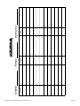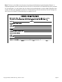
1
Operations Manual for the
Model Number 220
Always Read Instructions Before Use
This operations manual should be left with the Perfect Descent at
all times and shall only be removed by the end user. This manual
contains information about the safe use of the Perfect Descent
Climbing System as well as registration and warranty information.
Ensure that it is readily available to operators at all times.
CЄ0321
SERIAL#:
EN 341: 2011: Class C
Facilities using the Perfect Descent Climbing System should refer to, and abide by
the Climbing Wall Association Operations Standards which provides guidelines for the
indoor climbing industry, including age restriction, waiver forms, belay checks and climbing
facility operating procedures. Also refer to and abide by the Climbing Wall Association’s
Engineering Standards, the climbing industry standard for load distribution and anchor
point placement for artificial climbing walls. Instructions contained herein supersede any
information in these publications. Both publications are available through the Climbing
Wall Association (CWA).
Climbing Wall Association, Inc.
1460 Lee Hill Rd., Unit 2, Boulder, CO 80304-0870
Phone: 720-838-8284 Fax: 720-528-8200
www.climbingwallindustry.org
Copyright © 2013, C3 Manufacturing - Revision 5.13.13
Page 2
!
Important Notice About Safety
Read Before Installation and Operation
WARNING
Climbing is an inherently dangerous activity. Operators of the
Perfect Descent Climbing System are responsible for the safety and
supervision of climbers using this equipment. C3 Manufacturing
requires all operators to be trained before using this product. These
instructions must be provided to operators before use of the Perfect
Descent Climbing System and retained for reference by operators.
Owners and operators must read, understand (or have explained), and
heed all instructions, labels, marking, and warnings supplied with this
product, and with any associated products intended for use with the
Perfect Descent Climbing System. FAILURE TO DO SO MAY
RESULT IN SERIOUS INJURY OR DEATH.
Health and Safety
Owners and operators must abide by all Standards, International,
Federal, State and Provincial laws, and any specific health and safety
regulations pertaining to the installation and use of this product.
Site Plan Rescue
Owners and operators must have devised an emergency rescue plan
for any climber in distress at all sites operating the Perfect Descent
Climbing Systems. Operators must inform users of the Perfect Descent
of the procedure for rescuing a climber in distress prior to climbing.
!
Copyright © 2013, C3 Manufacturing - Revision 5.13.13
Page 3
TABLE OF CONTENTS
CERTIFICATION..................................................................................................................6
1.0 - DESCRIPTION OF PERFECT DESCENT CLIMBING SYSTEM............................ 7-8
1.1 - PERFECT DESCENT CLIMBING SYSTEM HOUSING ELEMENTS.........................7
1.2 - PERFECT DESCENT CLIMBING SYSTEM LABELS AND MARKINGS...................7
2.0 - MODEL 220 CE SPECIFICATIONS............................................................................9
2.1 - MODEL 220 NON-CE SPECIFICATIONS..................................................................9
3.0 - UNPACKING THE PERFECT DESCENT CLIMBING SYSTEM..............................10
3.1 - PRIOR CONSIDERATIONS....................................................................................10
3.2 - CONTENTS IN PACKAGE......................................................................................10
3.3 - UNPACKING THE PERFECT DESCENT CLIMBING SYSTEM..............................10
3.4 - TRANSPORTATION................................................................................................10
4.0 - INSTALLATION INSTRUCTIONS.............................................................................11
4.1 - PRIOR CONSIDERATIONS....................................................................................11
4.1.1 - MOISTURE......................................................................................................11
4.1.2 - PLACEMENT............................................................................................. 11-12
4.1.3 - HANDLING......................................................................................................12
4.2 - ANCHORING THE PERFECT DESCENT CLIMBING SYSTEM USING
APPROVED ANCHORAGE HARDWARE.............................................................. 12-13
4.2.1 - MOUNTING POINTS.......................................................................................13
4.2.2 - EYEBOLT........................................................................................................13
4.2.3 - INSTALLATION CARABINER..........................................................................14
4.2.4 - ANCHOR SHACKLE.......................................................................................14
4.2.5 - COMPATIBILITY OF ANCHORAGE COMPONENTS......................................14
4.3 - ANCHORING THE PERFECT DESCENT CLIMBING SYSTEM,
CUSTOM INSTALLATION...........................................................................................14
4.3.1 - Utilizing Units for Descending from Elevated Platforms.......14
5.0 - TRAINING..................................................................................................................15
5.1 - USER INSTRUCTION.............................................................................................15
6.0 - USAGE LIMITATIONS...............................................................................................16
7.0 - HARNESSES.............................................................................................................16
8.0 - SUPERVISION DURING USE...................................................................................17
Copyright © 2013, C3 Manufacturing - Revision 5.13.13
Page 4
9.0 - PROPER DESCENDING METHOD..........................................................................18
10.0 - CARABINER OPERATION......................................................................................18
11.0 - CARE, MAINTENANCE AND STORAGE...............................................................19
11.1 - REPLACING THE LINE (AND CARABINER).........................................................19
11.2 - CLEANING INSTRUCTIONS................................................................................19
11.3 - MAINTENANCE AND SERVICE...........................................................................20
11.4 - STORAGE............................................................................................................20
11.5 - SPARE PARTS AND ACCESSORIES...................................................................20
12.0 - LABELS AND MARKINGS......................................................................................21
13.0 - PERFECT DESCENT CLIMBING SYSTEM INSPECTION....................................22
13.1 - INSPECTION BEFORE USE.................................................................................22
13.2 - WEEKLY INSPECTION.........................................................................................22
13.3 - FORMAL INSPECTION........................................................................................22
13.3.1 - FORMAL INSPECTION FREQUENCY..........................................................22
13.3.2 - CONTROL OF EQUIPMENT.........................................................................23
13.3.3 - FORMAL INSPECTION PROCEDURE..........................................................23
13.3.3.1 - DIAGRAM.............................................................................................23
13.3.3.2 - FORMAL INSPECTION LOG................................................................23
13.3.3.3 - FORMAL INSPECTION CHECKLIST....................................................24
13.3.3.4 - FORMAL INSPECTION PROCEDURAL STEPS, HOUSING.................24
13.4 - FORMAL INSPECTION DIAGRAM.......................................................................25
13.5 - FORMAL INSPECTION LOG................................................................................26
13.6 - FORMAL INSPECTION CHECKLIST...................................................................27
14.0 - FACTORY SERVICE................................................................................................28
14.1 - FACTORY SERVICE.............................................................................................28
14.2 - OWNER REGISTRATION.....................................................................................28
14.3 - WHEN FACTORY SERVICE IS NECESSARY.......................................................28
14.4 - HOW TO OBTAIN FACTORY SERVICE................................................................29
14.5 - SERVICE AND INSPECTION LOGS.....................................................................30
14.6 - FACTORY SERVICE LOG............................................................................... 30-31
WARRANTY INFORMATION............................................................................................33
Copyright © 2013, C3 Manufacturing - Revision 5.13.13
Page 5
CERTIFICATION
• If the Perfect Descent is resold outside of the country of destination, the reseller must provide instructions
for use, maintenance, periodic examination, service, and repair in the language of the country of use.
• The Perfect Descent can be used as a climbing system device only in combination with other
components. It shall not be deemed suitable for use until it is ensured that the entire system complies with the requirements of appropriate regional, state, and federal directives/standards.
• Perfect Descent complies with the following prevailing safety regulations:
oAS/NZS 1891: Industrial fall-arrest systems and devices - Part 3: Fall arrest devices
oCSA Z259.2.3-99: Descent control devices
oEN 341: 2011: Class C: Personal protection equipment against falls from
height-descender devices
oANSI/ASSE Z359.4: Safety requirements for assisted-rescue and self rescue systems,
subsystems and components
• Notified body for CE type examination
oSATRA Technology Centre
Wyndham Way
Telford Way
Kettering
Northamptonshire
NN16 8SD
United Kingdom
• Body controlling the manufacture
oSATRA Technology Centre
Wyndham Way
Telford Way
Kettering
Northamptonshire
NN16 8SD
United Kingdom
Copyright © 2013, C3 Manufacturing - Revision 5.13.13
Page 6
1.0DESCRIPTION OF PERFECT DESCENT CLIMBING SYSTEM
The Perfect Descent Climbing System is a controlled descent device for recreational climbing, and is used in
indoor climbing gyms, on portable climbing walls, or challenge courses. It is installed where a top-rope would
be, thus eliminating the need for a belayer by providing a hands free belay for the climber. Once the climber
lets go of the wall, however, the climber cannot hang suspended by the Perfect Descent Climbing System,
and will automatically be lowered to the ground at a continuous, controlled rate. The line automatically
retracts into the unit, permitting repeated descents. The Perfect Descent Climbing System is NOT designed
for lead climbing and is not intended to be used as a personal issue item.
1.1PERFECT DESCENT CLIMBING SYSTEM HOUSING ELEMENTS
• INSTALLATION HANDLE
oConnection point for anchoring the Perfect Descent Climbing System to the climbing
structure. Also serves as a carrying handle. Anchoring elements should always secure through the installation handle.
• BRAKE HOUSING
o The metal housing that contains the brake mechanism. Brake dust exits the unit via a hole in the bottom of the brake housing. Always orient the Perfect Descent climbing system
vertically with this hole facing down.
• TAMPER RESISTANT BOLTS
oProvides evidence that the system has been tampered with by other than an authorized
factory representative. NEVER open the housing or attempt a field repair.
Serious injury could result.
• NOZZLE
oHelps seal the unit, prevent contaminants from entering the housing, and prevents line twisting.
• LINE
o 1” nylon wear indicating webbing. This is a yellow lanyard with a black wear indicator on each side. Should the lanyard wear though on any indicator, it must be replaced.
• SWIVEL CARABINER
oProvides a self-locking attachment means to the climber’s harness.
1.2PERFECT DESCENT CLIMBING SYSTEM LABELS AND MARKINGS
• FACE LABEL
oContains product information and model number.
• BACK LABEL
oExplains inspection before use and installation instructions. Reading the back label is not a
substitute for reading and understanding these Operator Instructions.
• SERVICE DATE LABEL
oCompleted by the manufacturer. Provides information vital to the inspection and factory
service procedures explained in Section 14. This label is located on the side of the unit.
• CE LABEL
o Provides CE Device Specifications. This label is located on the side of the unit.
Copyright © 2013, C3 Manufacturing - Revision 5.13.13
Page 7
CЄ0321
EN 341: 2011: Class C
Notified body
for CE type
examination
EN standard and
device classification
Copyright © 2013, C3 Manufacturing - Revision 5.13.13
Page 8
2.0 MODEL 220 CЄ SPECIFICATIONS
• Line specs: 8.5, 12.2, or 15.9m (28, 40, or 52ft.) long, comprised of 1” Nylon/ Spectra Webbing
• Maximum mounting height
o 8.5m (28ft) unit: 8.5m (28ft)
o 12.2m (40ft) unit: 12.2m (40ft)
o 15.9m (52ft) unit: 15.9m (52ft)
• Case Dimensions: 40x24x19 cm (16x9.5x7.5 in)
• Net Weight: 15 kg (33 lbs)
• Decent rate:
oMaximum: 2m/s (6.6 ft/s)
oMinimum: 0.5 m/s (1.6 ft/s)
• Maximum weight of climber: 110 kg (242 lbs)
• Minimum weight of climber: 40 kg (88 lbs)
• Minimum temperature for use: 0° C
• Materials
oCasing: stainless steel and aluminum
oLine: minimum breaking strength 15.6 kN (3,500 lbs) when new
oInternal parts: stainless steel and/or aluminum
* Perfect descent device is designed to be used on its own as a means of protecting a person during a fall
by descending them to the ground safely. The EN 341: 2011 dynamic strength test result also meets the
requirements of EN 360:2002, Personal protective equipment against falls from a height- Retractable type
fall arresters, clause 4.5 dynamic performance, with the exception of the arrest distance requirement. This
requirement is not applicable, as the device has no locking function, but still keeps the breaking force below
the acceptable limits of EN 360: 2002.
2.1 MODEL 220 NON-CЄ SPECIFICATIONS
• Line specs: 28, 40, or 52ft. (8.5, 12.2, or 15.9m) long, comprised of 1” Nylon/ Spectra Webbing
• Maximum mounting height
o 28 ft (8.5m) unit: 28 ft (8.5m)
o 40 ft (12.2m) unit: 40 ft (12.2m)
o 52 ft (15.9m) unit: 52 ft (15.9m)
• Case Dimensions: 16x9.5x7.5 in (40x24x19 cm)
• Net Weight: 33 lbs (15 kg)
• Decent rate:
oMaximum: 6.6 ft/s (2m/s)
oMinimum: 1.6 ft/s (o.5 m/s)
• Maximum weight of climber: 310 lbs (140 kg)
• Minimum weight of climber: 35 lbs (16 kg)
• Materials
oCasing: stainless steel and aluminum
oLine: minimum breaking strength 3,500 lbs (15.6 kN) when new
oInternal parts: stainless steel and/or aluminum
Copyright © 2013, C3 Manufacturing - Revision 5.13.13
Page 9
3.0UNPACKING THE PERFECT DESCENT CLIMBING SYSTEM
3.1PRIOR CONSIDERATIONS
• Ensure that this operations manual is readily available to Perfect Descent users at all times. It contains information relating to the safe use of the Perfect Descent Climbing System and includes all product registration and warranty information. It may only be removed by the end user.
• DO NOT DISPOSE OF THE PACKAGING
o The cardboard box and internal packing materials will be required for the return of the unit every two years for inspection. Please keep the packaging in a safe, dry place until required.
3.2CONTENTS IN PACKAGE
• The Perfect Descent Climbing System is packaged in a cardboard box and contains:
o 1 Perfect Descent Climbing System
o 1 Lanyard, either 28, 40, or 52 feet (8.5, 12.2, or 15.9m)
o 1 Carabiner
o 1 Operations Manual
o 1 Warranty Registration Card
3.3 Unpacking the Perfect Descent Climbing System
• Upon receipt of the unit, first inspect the box for signs of shipping damage. If there appears to be damage, contact your Perfect Descent distributor.
• Check to see that all labels are affixed to the Perfect Descent and legible.
• Check the Certification Label for the “Next Service Due.” If the date shown has passed or the label is missing or illegible, the Perfect Descent must not be put into service.
• Fill out the Owner Registration Card and return it for product registration.
• Read the Operations Manual and familiarize yourself with all aspects of installation, operation, care and maintenance.
3.4 Transportation
• If the Perfect Descent is to be returned to C3 Manufacturing or an
authorized service center for servicing please return it in the original
packaging. Repackage Perfect Descent as shown:
Copyright © 2013, C3 Manufacturing - Revision 5.13.13
Page 10
4.0 INSTALLATION INSTRUCTIONS
4.1PRIOR CONSIDERATIONS
4.1.1MOISTURE
• If moisture is allowed to remain in contact with the internal mechanism, the effectiveness of the
braking system as well as the useful life of the Perfect Descent Climbing System may be reduced. The Perfect Descent Climbing System has one opening where water can enter the internal mechanism:
the nozzle. When the Perfect Descent Climbing System is installed correctly with the nozzle facing straight down, moisture will flow primarily over the protective housing, or drain out through the nozzle opening. It is important that the Perfect Descent Climbing System is installed in an upright position.
DO NOT MOUNT THE PERFECT DESCENT CLIMBING SYSTEM HORIZONTALLY. Mounting the
device horizontally will permit moisture and brake dust to accumulate inside the brake housing.
Prolonged exposure to moisture will cause corrosion to the brake mechanism and can contribute to mechanical malfunction such as difficulty in retracting or extracting line.
WARNING
Ensure that the brake mechanism is dry prior to operation. If the brake mechanism remains wet a
climber may experience an increased rate of descent, or jerky descent.
• When transporting or storing the Perfect Descent Climbing System on a portable rock wall, always remove the device, or cover it with a waterproof cover to prevent water damage. This is especially
important if the device will be transported or stored in a horizontal position, where water or road salts
can enter and remain trapped inside the mechanism for extended periods. A protective cover can be
created from a plastic bag or tarpaulin, as long as the cover prevents water from entering and
remaining inside the Perfect Descent Climbing System. Remove or cover the unit whenever the rock wall is laid horizontally. Do not lay the Perfect Descent Climbing System down where water can enter and remain inside the unit.
4.1.2PLACEMENT
• Install the Perfect Descent Climbing System with sufficient clearance to permit freedom for the device to rotate several inches back-and-forth and side-to-side. DO NOT rigidly mount the Perfect Descent Climbing System to the climbing wall, as this can result in premature wear of the line.
• When utilizing units for descending from elevated platforms, mount your unit so that the attachment
carabiner hangs 6 feet above the height of the platform floor. Mount your unit at a distance of 20-24
inches protruding from the platform.”
WARNING
DO NOT rigidly mount the Perfect Descent Climbing System to the climbing wall.
• Install the Perfect Descent Climbing System over the intended descent path with the housing oriented vertically and line nozzle facing down. The housing must be oriented vertically to permit proper
operation of the brake mechanism and to allow brake dust to exit the housing during maintenance. Install where the line can hang unobstructed by the climbing wall or climbing holds. Do not allow the
line to pass over sharp edges or drag on the wall or hand holds during descent. Always avoid
installation where the line can become lodged behind hand holds or other obstructions. Mount the
Perfect Descent Climbing System so as to prevent a climber from climbing above the unit. Install the
Copyright © 2013, C3 Manufacturing - Revision 5.13.13
Page 11
•
•
unit overhead to minimize swing hazards, and to prevent excessive wear on the nozzle. Ensure that the
height of the wall does not exceed the line length of the lanyard; either 28, 40, or 52 ft. (8.5, 12.2, or
11.9m) depending on which lanyard is in the unit. Also ensure that climbers cannot forcibly extract the
line beyond this length to its termination point. If installation is on a portable climbing wall, secure the
unit where it is easily accessed for inspection and removal prior to transport.
Consider all possible paths of climber movement and all factors that could affect climber safety while climbing and descending, anywhere along these paths. Consider the location of the entire length of line as the prospective climber moves around. It should not pass over, under or around the path of
another climber. Never install the Perfect Descent Climbing System where the housing or line can
encounter electrical hazards.
Always mount the Perfect Descent with the Back Label facing the wall and the Brake Drum facing away from the wall.
4.1.3HANDLING
• Take care when lifting the Perfect Descent Climbing System as it is a heavy item: 33 lbs (15 kg).
• Take precautions to avoid dropping the Perfect Descent Climbing System when it has been detached
from the climbing wall. Damage can occur to the brake mechanism if the Perfect Descent Climbing
System is dropped. This damage may not be evident upon inspection of the external housing, and
may result in interference with normal line retraction. If you suspect that a Perfect Descent Climbing
System has been dropped, resulting in damage to the brake mechanism, remove the unit from use
immediately and return to C3 Manufacturing or an authorized service center for service.
• When not in use, the line of the Perfect Descent Climbing System should be retracted completely into the housing. This will prolong the life of the retraction spring. Never release the line, allowing it to re-reel
back into the Perfect Descent Climbing System in an uncontrolled manner. When not in use, a tag
line can be connected to the carabiner for retrieving and returning the line into the housing. While in
use, it is recommended to keep the carabiner clipped to an eyebolt or hanger at the base of the climb,
where it is available to the operator.
4.2 ANCHORING THE PERFECT DESCENT CLIMBING SYSTEM USING
APPROVED ANCHORAGE HARDWARE
• The Perfect Descent Climbing System must be linked to an anchorage so as to prevent accidental
disengagement or rollout. There are many elements of installation hardware that are suitable for
installation. The information that follows discusses a few that are in general use and readily
available. Most installations can be accomplished using these hardware elements individually or
combined as described. All installation methods and hardware must meet the minimum requirements
set forth by these instructions. Never use installation methods and hardware other than those
recommended by C3 Manufacturing unless such other hardware and methods have been
recommended to be suitable by C3 Manufacturing, or approved by a qualified engineer. All installation hardware and the mounting location on the climbing structure must meet a minimum strength
requirement of 4,400 lbs (19.6 kN) in the direction of anticipated loading.
• All anchor points and connectors used with the Perfect Descent must conform to any federal or state requirements for such devices.
• Minimum requirements for anchor points must conform to the requirements of EN 12572: Climbing wall anchor points, and EN 795: Anchor Devices.
• The location and anchor points for the Perfect Descent should comply with the following:
Copyright © 2013, C3 Manufacturing - Revision 5.13.13
Page 12
oMinimum load capacity of the anchor point(s) of 4,400lbs (19.6 kN) in expected directions of
application.
oAnchor points are not to be used by other devices or as attachments for hardware not associated with the Perfect Descent installation.
oAnchor points should be a suitable size to correctly install any mounting hardware.
• All secondary connectors and hardware used in the installation of the Perfect Descent must conform
to the requirements of EN 362: Types of connectors for personal protection, and EN 12275- Types of connectors for mountaineering.
4.2.1 MOUNTING POINTS
• The only place the Perfect Descent is to be mounted from is the handle. It can either be mounted with a single or double point mounting.
oFor single point mounting, only one connection point is connected to the handle as shown below.
oFor double point mounting, two connection points are connected to the handle, one on either side as shown below.
SINGLE POINT
MOUNTING
DOUBLE POINT
MOUNTING
4.2.2EYEBOLT
• Eyebolts must be of weld-less forged alloy steel construction with a shoulder pattern, threaded shank, washer and nut. The length of shank and diameter of the threaded cross-section shall be appropriate
for the specific installation. The breaking strength must be a minimum 4,400 lbs (19.6 kN) for any
loading direction anticipated by the system. Verify that
intermediate anchorage connectors (carabiner or shackle) are
compatible to prevent accidental disengagement (“rollout”).
Proper selection and installation must be performed under
the supervision of a qualified person. Always install the eyebolt
such that the anticipated loading direction is within 30° of the
eyebolt axis. Never install to an eyebolt mounted horizontally.
Eyebolts without a nut are not recommended because they can
work loose. Verify that the nut is properly torqued against the
washer and will not loosen over time, and that the structure to
which the eyebolt is mounted is capable of supporting
4,400 lbs (19.6 kN) in the direction of an¬ticipated loading.
Copyright © 2013, C3 Manufacturing - Revision 5.13.13
Page 13
4.2.3 INSTALLATION CARABINER
• Two locking steel carabiners can be used as an anchorage connector when linked between the Perfect Descent Climbing System Installation Handle and an appropriate anchorage connector. While one
carabiner is sufficient, two is recommended to spread load and reduce wear on the handle. Each
carabiner has a minimum breaking strength of 5,000 lbs. Always verify that the carabiners are loaded along their major axis, with the gate closed and locked. Loading the carabiners in any other manner will reduce their strength to the point where it may fail. Contact C3 Manufacturing for information and separate user instructions for the selection and use of this equipment.
4.2.4 ANCHOR SHACKLE
• A bolt-type anchor shackle that is of weld-less forged alloy steel construction may be used as a link between the Perfect Descent Climbing System Installation Handle and an appropriate anchorage
connector. Shackles should comply with U.S. Federal Specification RR-271. These are referred to as
safety anchor shackles because the shackle bolt is secured with a nut and a cotter pin to reduce the
possibility of the bolt coming out. It is recommended that the shackle with a nominal 0.5 inches be used. Never replace an original shackle bolt with a regular bolt. Never use the shackle without the nut and cotter pin in place. The Perfect Descent Climbing System installation handle should bear on the shackle bow.
4.2.5COMPATIBILITY OF ANCHORAGE COMPONENTS
• Connecting hardware must be compatible in size, shape, and strength. Non-compatible connectors may accidentally disengage (“rollout”). Always verify that connection elements of the anchorage are compatible.
4.3 ANCHORING THE PERFECT DESCENT CLIMBING SYSTEM, CUSTOM INSTALLATION
• It is possible to design and fabricate a custom means of installation. Installation must meet the minimum anchorage strength requirements of 4,400 lbs (19.6 kN) in the direction of anticipated loading. When designing a custom installation, consider and eliminate any potential obstructions that could compromise the proper function and line extraction of the Perfect Descent Climbing System. C3 Manufacturing does not recommend that the line pass over a pulley or sheave, so as to orient the housing off of vertical. All custom installations must be designed or approved by a qualified engineer. Mount the Perfect Descent Climbing System in a manner that ensures that it will not work loose. Always anchor the Perfect Descent Climbing System through the Installation Handle.
4.3.1 Utilizing Units for Descending from Elevated Platforms
• Mount your unit so that the attachment carabiner hangs 6 feet above the height of the platform floor. Mount the unit at a distance 20” - 24” protruding from the platform. Ensure the descent path and landing area are free of people and obstructions.
Copyright © 2013, C3 Manufacturing - Revision 5.13.13
Page 14
5.0TRAINING
It is the responsibility of the purchaser of the Perfect Descent Climbing System to assure that operators read
and understand these operator instructions, and are trained in:
•
•
•
•
•
•
How to properly inspect, use, transport, store and maintain the Perfect Descent Climbing System.
How to properly install the Perfect Descent Climbing System.
Proper attachment locations and methods, including compatibility of connections to eliminate the
possibility of accidental disengagement.
The consequences of improper use of the Perfect Descent Climbing System and associated
equipment, and of failure to follow instructions and training.
How to instruct climbers on the proper use of the Perfect Descent Climbing System.
How to supervise climbers using the Perfect Descent Climbing System.
It is the responsibility of all operators of the Perfect Descent Climbing System to ensure that all
users (climbers) are:
• Properly fit and secure in a manufactured climbing harness.
• Properly attached by the Perfect Descent Climbing System carabiner to their climbing harness.
• Instructed on proper techniques for ascending and descending using the Perfect Descent
Climbing System.
• Instructed on what to do in the event that a slack line condition, or improper retraction rate is observed while climbing.
5.1USER INSTRUCTION
• Prior to clipping in, all climbers must be instructed in the safe use of the Perfect Descent. Operators are to insure that all climbers are familiar with the site rescue plan in the event the climber becomes
disttressed. Climbing is considered a strenuous activity. If you have any physical or medical condition that may affect your climbing ability, consult a medical professional prior to participation.
• Ensure the carabiner is attached to the climbing harness per manufacturer’s recommendation and the latch is fully closed and the gate engaged before starting to climb. FAILURE TO DO SO CAN RESULT IN SERIOUS INJURY OR DEATH.
• Prior to climbing, the user must be aware of, and completely understand the following precautions:
oCheck Perfect Descent by pulling out a short section and allowing it to retract.
oIn the Perfect Descent line fails to retract during climbing, stop climbing immediately and request assistance.
o Check the climbing harness is correctly fitted and tightened.
oCheck the carabiner from the Perfect Descent lanyard is connected to the designated attachment point on the climbing harness and the gate is properly closed.
oEnsure the carabiner latch gate is facing away from the climber.
oNever climb alongside or above the Perfect Descent.
oNever start descent from above the Perfect Descent.
oPrior to descent, ensure descent path and landing area are free of people and obstructions.
o Always descent feet first using feet to fend off obstacles and prepare for landing.
Copyright © 2013, C3 Manufacturing - Revision 5.13.13
Page 15
6.0USAGE LIMITATIONS
• The Perfect Descent Climbing System is designed for use by one person at a time. The designed
weight range is between 88 lbs and 242 lbs (40 and 110 kg) for CЄ standard and 35 lbs and 310 lbs
(16 and 140 kg) for non CЄ standard. Persons with muscular, skeletal, or other physical disorders
should consult a physician before using the Perfect Descent Climbing System. Consult a physician if
there is any question about physical ability to safely climb or use this product.
• Do not expose the Perfect Descent Climbing System to environments with prolonged temperatures
greater than 185° F (85° C). Do not expose the Perfect Descent Climbing System to a corrosive
environment. Always remove or seal the unit during trailer transport. The Perfect Descent Climbing
System internal parts should be protected from dirt, salt and water. Do not install where the unit or
line can come in contact with an electrical source. Any Perfect Descent Climbing System that shows
signs of excessive wear, deterioration, malfunction, or insufficient retraction force must be removed
from use and marked as “Unusable” until returned to a C3 Manufacturing approved service center for
repair. (See section 13 for detailed inspection procedure, and section 14 for factory service
information.)
• The performance of the brake mechanism will change slightly over the life of the Perfect Descent
Climbing System. Once the brake pads have worn in, descent rate will be slightly slower than when the
unit was new. This change in performance is expected and normal. The brake pads will produce an
intermittent sound when the line is slowly extracted.
7.0HARNESSES
• All harnesses used in conjunction with the Perfect Descent Climbing System must comply with the
following standards:
oEN 361 – Personal protective equipment for prevention of falls from a height – Full body harness
oEN 813 – Personal protective equipment for prevention of falls from a height- Sit harness
o EN 12277 – Type A Full Body Harness
o EN 12277 – Type B Small Full Body Harness
o EN 12277 – Type C Sit Harness
• Follow manufacturer’s recommendations for fitting, attachment and proper threading of buckles. The
Perfect Descent Climbing System carabiner should be attached through the tie-in point(s) on a
harness, per the manufacturer’s instructions. Operators should always check for proper harness fit and
attachment to the Perfect Descent Climbing System carabiner prior to climber ascent. Refer to the
manufacturer’s instructions and the Climbing Wall Association’s website for information on the design,
use, maintenance and limitations of climbing harnesses.
Copyright © 2013, C3 Manufacturing - Revision 5.13.13
Page 16
8.0 SUPERVISION DURING USE
• Training provided by the operator to users (climbers) of the Perfect Descent Climbing System should
include, as a minimum, those areas outlined in section 5.0.
• Climbers should be under constant supervision by a trained operator. Before ascending the wall,
operators should check to verify that each climber has:
o Properly fit and secured climbing harness.
oProperly clipped their harness onto the Perfect Descent Climbing System carabiner.
• Once the climber’s harness is attached, always check that the gate on the carabiner is locked and
secure by depressing the gate.
• Operators should provide instructions regarding proper technique for ascending and descending the
wall while using the Perfect Descent Climbing System.
• Do not allow climbers to ascend above the Perfect Descent Climbing System, or climb off route or in
the path of another climber.
• Climbers should be prevented from climbing on an area of the wall that would produce a swinging fall.
• Always maintain a safe, unobstructed landing area that is free of objects and other climbers.
• Discourage climbers from releasing the line, allowing it to re-reel back into unit in an uncontrolled
manner.
• Do not allow climbers to loop the line around holds, or secure the line through quickdraws in order to redirect descent.
• Do not allow the line to become wrapped around the arms, legs or neck.
• Operators should warn climbers not to allow a slack line to develop. A slack line resulting in free-fall
could seriously injure a climber or break the line. Instruct the climber that in the event of a slack line, he
or she should remain stationary on the wall, and notify the operator immediately. If a climber has
ascended without recognizing the slack line, the climber should be instructed to remain in place on the wall. Rescue the climber by attaching their harness to a secondary lowering system, (top rope or
second Perfect Descent Climbing System) and lowering them to the ground. Always ensure that this
rescue system is available and in place, and that all operators have been trained on a rescue
procedure.
• It is very important to utilize your device without shock loading or dynamic loading your descender. Repetitive shock loading your unit will cause serious gear and axle damage to the unit, which can result
in an accelerated descent speed and even unit failure.
• It is most important to utilize your device without shock loading or dynamic loading your descender.
Repetitive shock loading your unit will cause serious gear and axle damage to the unit, which can result
in an accelerated descent speed and even unit failure. Users are required to sit back or step off the
platform. Under no circumstances should they swing, jump, or hop out for the start of their descent.
Copyright © 2013, C3 Manufacturing - Revision 5.13.13
Page 17
9.0PROPER DESCENDING METHOD
• When descending, the climber should let go of the climbing wall, transferring their weight to the Perfect Descent Climbing System. The climber will feel little tension on the line until he/she has begun the
descent. The climber should sit back in their harness and walk their feet down the wall. Always
provide a safe, unobstructed landing surface.
• When utilizing this device as a means of egress from an elevated platform, users should sit back or
step off the platform. Under no circumstances should they swing, jump or hop out for the start of their descent.
• If a climber is anxious or unfamiliar with the function of the Perfect Descent Climbing System, it is
recommended that the climber ascend a short distance and descend in order to become aquatinted
with the device. We recommend that young children be belayed using a standard belay system.
Younger children tend to want to hang onto the line and will not gain positive progress up the wall.
10.0 CARABINER OPERATION
•
•
The carabiner provided with Perfect Descent Climbing System is either a two stage or three stage selfclosing and self locking carabiner.
The Two Stage Carabiner is opened by first twisting the knurled gate collar 90° and then depressing
the gate.
• The Three Stage Carabiner is opened by first lifting the collar until it stops, then twisting the knurled gate collar 90°, and then depressing the gate.
• When attaching the carabiner to a harness, verify that the harness webbing or clothing is not
obstructing closure of the gate. Always check the gate after attaching to the manufacturer recom-
mended harness attachment point(s) by depressing the gate to verify that it is fully closed and locked.
WARNING
Double check to make sure the carabiner gate has properly closed and latched prior to use.
Copyright © 2013, C3 Manufacturing - Revision 5.13.13
Page 18
11.0 CARE, MAINTENANCE AND STORAGE
• Inspect the Perfect Descent Climbing System by following the guidelines laid out in section 13 of this manual.
• The useful life of the Perfect Descent Climbing System is dependent upon the operator’s proper care of
the unit, including maintenance and storage. If the Perfect Descent Climbing System is used on a
portable climbing wall, always remove the Perfect Descent Climbing System, or seal the unit from
water, salt, and contaminants before transport. Factory service is required every two years to keep the
product in good working condition and ensure its integrity. Proper care and maintenance of the
product by the operator is essential during the two year intervals between factory servicing.
oPrevent denting or deformation of the housing. Never drop the unit from any height, and always
set it down carefully.
oWhen in use, protect the line from contacting sharp corners and edges.
oDO NOT allow foreign matter to enter the housing.
oHeed all caution labels and instructions as these are intended to prevent damage to the product
as well as guide the operator in correctly operating the Perfect Descent Climbing System.
• DO NOT STORE IN A WET CONDITION
oAfter exposure to water or damp conditions, thoroughly clean and dry the Perfect Descent.
Ensure that the unit is not left with wet webbing line retracted inside the casing. Always store the unit in a clean, dry environment.
11.1 REPLACING THE LINE (AND CARABINER)
• The Perfect Descent Climbing System comes equipped with a line that may be replaced in the field by
the owner/operator. If a line appears damaged, excessively fuzzy, worn, sun bleached, or if the wear
indicators have worn through, it should be replaced immediately. Replace the line as part of the regular
maintenance schedule. Always keep a replacement line and the appropriate tools on hand in the event
that a line requires immediate replacement. Frequency of replacement will vary depending upon use. Line replacement kits can be ordered from can be purchased from an authorized dealer or service
center. Full instruction for the line replacement is included with the line replacement kit.
11.2CLEANING INSTRUCTIONS
• To clean the housing, periodically use a clean, damp (not wet) cloth to remove dirt or contamination which may cause corrosion or hamper readability of labels. Wipe off any moisture before returning the
Perfect Descent Climbing System to service. The frequency of cleaning should be determined by
inspection and by severity of the environment. In highly corrosive environments, cleaning will be
required more often. Never use solvents to clean the housing as they may break down the label
adhesive. DO NOT use abrasives to scour the housing as they may damage the plating and the labels.
Never immerse the product in water or other liquid. If water gets into the housing, hang the device and
slowly extract the entire lifeline allowing the water to run out of the lifeline orifice. Use a clean dry cloth
to wipe the line dry as it is slowly re-reeled back into the device. Leave the device hanging in a warm
dry room with the line extracted. Questions concerning Perfect Descent Climbing System condition
and cleaning should be directed to C3 Manufacturing.
Copyright © 2013, C3 Manufacturing - Revision 5.13.13
Page 19
11.3 MAINTENANCE AND SERVICE
• Major maintenance can only be performed at the factory, but the routine maintenance, specified herein
is permissible for the operator to perform. Proper maintenance is both preventive and corrective in nature.
• Proper maintenance of the Perfect Descent Climbing System includes regular cleaning of the brake
drum and unit housing to remove brake dust. A Perfect Descent Climbing System that is under
continual use should be cleaned weekly. Unscrew the drain plugs using a 3/16” allen wrench and use a vacuum to remove air and dust from the drain hole in the bottom of the metal housing. Dust
can be removed from the unit housing by removing the lanyard nozzle on the bottom of the unit. While
vacuuming, slowly extract and retract the line in order to rotate the internal brake shoes. Repeat
several times until all dust has exited the brake drum and unit housing. Replace the screw in plugs until
they are snug. Do not over tighten them. Maximum torque that should be applied is 60”/lbs. Regular
maintenance will help prolong the life of the brake shoes, and ensure a smooth descent. A non-smooth
descent indicates that the brake housing should be cleaned more frequently.
• Proper maintenance of the carabiner includes cleaning and lubricating the gate hinge, swivel and
locking collar with a cleaning lubricant, such as WD-40. Spray the carabiner with lubricant between all
moving parts, and activate the locking gate and swivel several times to assist lubricant penetration.
DO NOT allow lubricate to contact the nylon line as this may weaken the line. Wipe off any excess
lubricant and allow to dry. If the gate is ever observed to stick open or unlocked during use, take the
Perfect Descent Climbing System out of service immediately until it is properly lubricated and it is
verified that the connector will close and lock automatically. If lubrication does not correct the problem,
immediately remove the Perfect Descent Climbing System from use until the line has been replaced
with a Line Replacement Kit.
• Equipment which is damaged or in need of maintenance must be tagged as “UNUSABLE” and
removed from service. Corrective maintenance (other than cleaning) and repair, such as replacement of
elements, (other than the line with integral nozzle and attachment element), must be performed only by
C3 Manufacturing or an authorized service center. Do not attempt field repairs.
11.4STORAGE
• Store the Perfect Descent Climbing System in a cool, dry and clean place. Avoid areas where heat, moisture, oil and chemicals or their vapors or other degrading elements may be present. Heavily soiled, wet, or otherwise contaminated equipment should be properly maintained (e.g. dried and cleaned) prior to storage. Ensure that the exterior line does not come in contact with grease, oils, gas, or other chemicals that may weaken it.
• Never allow the Perfect Descent Climbing System to rest for lengthy periods of time on concrete or ash floors as the lime sulfur and ash can cause corrosion. Store the device with the lifeline fully retracted. Prior to using equipment which has been stored for long periods of time, a Formal Inspection should be performed by a competent person.
11.5 SPARE PARTS AND ACCESSORIES
• Your Perfect Descent is fitted with a number of user replaceable parts that may be refitted without the need to return the device to an authorized service center. Always follow the instructions as detailed in
the User Manual and any Part Replacement Guide supplied with undertaking the replacement of a part.
• Replacement parts that can be ordered include:
oLanyard replacement kit
oNozzle replacement kit
Copyright © 2013, C3 Manufacturing - Revision 5.13.13
Page 20
12.0 LABELS AND MARKINGS
• The following labels must be present, legible and securely attached to the Perfect Descent Climbing System. If not, remove the Perfect Descent Climbing System from use and mark it as “UNUSABLE”
until a Formal Inspection is performed.
Copyright © 2013, C3 Manufacturing - Revision 5.13.13
Page 21
13.0PERFECT DESCENT CLIMBING SYSTEM INSPECTION
13.1 INSPECTION BEFORE USE
• The Perfect Descent Climbing System should be inspected before each use to verify that the unit is
functioning properly. Check, by pulling on the line, for resistance produced by the braking mechanism.
Verify smooth, even deployment of the line. Return the line back into the housing in a controlled
manner and verify adequate and smooth retraction force. If inspection reveals improper function,
remove the Perfect Descent Climbing System from use immediately and submit for factory service. Do
not use the Perfect Descent Climbing System if inspection reveals an unsafe condition. IT IS
ESSENTIAL FOR SAFETY THAT EQUIPMENT IS WITHDRAWN FROM USE IMMEDIATELY
SHOULD ANY DOUBT ARISE ABOUT ITS CONDITION FOR SAFE USE AND NOT BE USED
AGAIN UNTIL CONFIRMED IN WRITING BY A COMPETENT PERSON THAT IT IS ACCEPTABLE TO DO SO.
13.2WEEKLY INSPECTION
• While the Perfect Descent Climbing System is in use, a thorough inspection should be performed
on a weekly basis. Inspect the sewn stitching at the end of the line for broken, frayed, or missing
threads. Inspect the line along its entire length, checking for excessive wear, burns, cuts, sun
bleaching, chemical or other damage. Also make sure the wear indicators have not worn through. If
any of these conditions exists, remove the unit from use until the line can be replaced. Examine the
function of the Perfect Descent Climbing System as specified in section 13.1. If the braking mechanism
produces loud chatter accompanied by a jerky descent, this is an indication that the brake housing
should be maintained according to section 11.3. Examine the line termination near the carabiner,
paying particularly close attention to the first few feet of line for damage. Check that the carabiner
functions properly, and automatically closes and locks when released. Follow the procedures in Section
10 if a carabiner fails to close or lock automatically.
• Check all bolts and nuts on the housing to be sure that they are tight. Check that no hardware is
missing, damaged, or has been improperly substituted or altered in any way. Check that the two
security rivets are in place and are stamped with an “&”. If missing, remove the product from use.
Check that the housing is not damaged or dented, and that the installation handle is not bent. Check
all metallic parts, including the carabiner and installation hardware, for deformation, fractures, cracks,
corrosion, cuts, deep nicks, and evidence of excessive heat or chemical exposure. Check for
excessive wear on the installation handle and nozzle. Check the anchorage hardware for excessive
wear, loose or missing components, and damage during transport or use. If any of these conditions
exist, remove from use and submit to factory service according to Section 14. Do not use the Perfect
Descent Climbing System if inspection reveals an unsafe condition.
13.3FORMAL INSPECTION
13.3.1 FORMAL INSPECTION FREQUENCY
• The Perfect Descent Climbing System must be formally inspected by a competent person at
intervals of no more than six months. If the Perfect Descent Climbing System is exposed to severe
conditions, more frequent formal inspections may be required. The frequency of inspection should be
established by the operator’s organization based on such factors as the nature and severity of
conditions, frequency of use, and exposure time of the equipment. The inspector should perform a
methodical and thorough visual and tactile inspection by following the inspection procedure in section
13.3.3. The inspection results should be recorded in the Formal Inspection Log and retained for
reference.
Copyright © 2013, C3 Manufacturing - Revision 5.13.13
Page 22
13.3.2CONTROL OF EQUIPMENT
• The operator’s organization should establish and enforce a policy and procedure whereby any Perfect
Descent Climbing System that is found to be defective, damaged, or in need of maintenance be
immediately removed from use, marked as “UNUSABLE” and immediately submitted to custody of the
person responsible for Formal Inspection. This has the benefits that:
1) defective equipment is secured from further use until proper action is taken;
2) uniform standards are applied for determining whether the equipment is acceptable or not
acceptable for further use;
3) uniform methods of cleaning, line and carabiner replacement and other maintenance are
applied;
4) there is a central point for evaluation of conditions that may be recurring and require preventive
measures such as coordination with the equipment manufacturer, selection of alternate
equipment, additional training of equipment users, or changes to the conditions of use.
13.3.3FORMAL INSPECTION PROCEDURE
• The Formal Inspection Procedure is similar to the weekly inspection described in section 13.2.
However, it differs in three important respects:
1) it is performed by a person who is trained and authorized to perform Formal Inspection
2) it is more detailed and is methodically recorded on a Formal Inspection Log that is kept on file for future reference
3) it results in final disposition of the equipment as either “acceptable” or as “not acceptable”
followed by factory service of the product.
• The described detailed inspection record keeping is needed in order to trace detected defects to their
causes. A simplified alternative procedure is also explained below.
• There are three forms that are important to the Formal Inspection Procedure. They are the Formal
Inspection Diagram (“DIAGRAM”), the Formal Inspection Log (“LOG”), and the Formal Inspection Checklist (“CHECKLIST”). These forms relate and refer to each other so it is necessary to understand their purposes and uses before discussing the inspection procedure.
13.3.3.1DIAGRAM
• This is a drawing of the Perfect Descent Climbing System with numbers corresponding to those on the Formal Inspection Log in the column titled “Inspection Number.” (See section 13.4)
13.3.3.2FORMAL INSPECTION LOG
• This form is to be used to record observations made during the Formal Inspection (See section 13.5).
The “Model Number,” “Serial Number,” and “Manufacture Date” may be found on the product label. The “Inspector,” “Inspection Date,” and “Condition of Unit” are to be entered upon inspection by the
inspector. The Condition of the Unit is to be termed either “Acceptable” or “Not Acceptable.”
• The columns on the LOG are as follows:
oInspection number: These numbers correlate to the numbers on the DIAGRAM.
oDescription: This is the name of the Perfect Descent Climbing System inspection point. There are four categories for the inspection: Lanyard, Carabiner, Casing/Brake Housing, and Handle.
o QTY: Quantity per Perfect Descent Climbing System. The quantity of each Perfect Descent
Climbing System inspection point that must be inspected
oComments: This is where the inspector indicates their observations.
oPass/Fail: This is where the overall condition of the Perfect Descent Climbing System is to be noted. If any defective conditions are observed with the Perfect Descent Climbing System, the inspector is to note “Fail” in this column. If no defective conditions exist, either leave it blank, or note “Pass.”
Copyright © 2013, C3 Manufacturing - Revision 5.13.13
Page 23
13.3.3.3FORMAL INSPECTION CHECKLIST
•
This table categorizes the different types of Perfect Descent Climbing System parts into four
categories: Lanyard, Carabiner, Casing/Brake Housing, and Handle (See section 13.6). For each of
these categories, the formal inspector checks the Perfect Descent Climbing System parts for each of the associated conditions (e.g. deformed, fractured, missing, loose, etc.). Any condition observed is to be noted in the “Overall Results” column, any concerns discussed in the “Comments” column, and then a pass or fail noted in the “Pass/Fail” column.
13.3.3.4FORMAL INSPECTION PROCEDURAL STEPS, HOUSING
• Step 1: Record on the LOG the Model Number, Serial Number and Manufacture Date information shown on the service and date label. Record the inspector’s name and inspection date.
• Step 2: Suspend the Perfect Descent Climbing System oriented vertically.
• Step 3: Inspect each part one at a time, referring to the DIAGRAM for identification of each
Inspection Point. Each part must be inspected for the possible presence of the conditions shown on
the checklist. Compare the results with the prior Formal Inspection records if there is any question
whether the Perfect Descent Climbing System condition has materially changed since the last
Formal Inspection.
• Step 4: Determine whether each part is acceptable or not acceptable, and note pass or fail in the Pass/Fail column of the LOG.
• Step 5: Perform a functional test of the Perfect Descent Climbing System carabiner by opening the gate and allowing it to release. Check for any hesitation in the closing of the gate. Check that the gate closes by itself. Note the results in the appropriate section of the Inspection Log.
• Step 6: Perform a functional test of the Perfect Descent Climbing System line extraction and
retraction features. Upon completion of these functional tests, note the performance for extraction
and retraction in the comments section on the Inspection Log. The extraction functional test is per
formed by slowly pulling the line, completely out of the Perfect Descent Climbing System housing. Note as the line is reeled from the drum if there is any sticking, hesitation, or other hindrances to the smooth deployment of the line. The retraction functional test is performed by allowing the automatic
retraction of the device to re-reel the line back into the Perfect Descent Climbing System. The tension
of the drum on the line as it draws the line into the Perfect Descent Climbing System should be
constant, the line should not snag or catch and there should not be any loud grinding noise throughout
the entire retraction of the line. Note that during normal operation the internal retraction spring will
produce a rubbing noise as line is extracted or retracted. This noise is more pronounced when the unit
is laid on its back, with the brake housing facing upward. Record the results of the functional tests in
the appropriate sections of the Inspection Log.
• Step 7: If it has been determined that the Perfect Descent Climbing System is not acceptable for use, contact C3 Manufacturing to determine if a servicing is required, or if the unit needs to be retired.
• Step 8: File the LOG for future reference.
Copyright © 2013, C3 Manufacturing - Revision 5.13.13
Page 24
13.4FORMAL INSPECTION DIAGRAM
Copyright © 2013, C3 Manufacturing - Revision 5.13.13
Page 25
13.5FORMAL INSPECTION LOG
Copyright © 2013, C3 Manufacturing - Revision 5.13.13
Page 26
13.6FORMAL INSPECTION CHECKLIST
Copyright © 2013, C3 Manufacturing - Revision 5.13.13
Page 27
14.0FACTORY SERVICE
14.1FACTORY SERVICE
• Proper maintenance and repair of the Perfect Descent Climbing System requires return of the unit to C3 Manufacturing (or to an authorized C3 Manufacturing Service Center) every two years or at any time that a competent person inspection suggests the need to remove the unit from use. The only maintenance that may be performed by the operator is cleaning, carabiner lubrication, and line
replacement. All other maintenance must be performed by C3 Manufacturing or an authorized service center. The operator must never attempt to repair or alter the unit. There are no internal parts which are serviceable or replaceable by the operator, and any attempt may void the warranty.
14.2 OWNER REGISTRATION
• When the Perfect Descent Climbing System is purchased, the first thing the owner and operator must
•
•
do is read this Operation Manual and return the Owner Registration Card packed with the device. Each
unit has a unique serial number which identifies all information associated with the unit. The serial
number enables C3 Manufacturing to identify when the product was made; related engineering,
manufacturing, testing and quality control records; related service records; and date it was sold and
shipped to the owner or a C3 Manufacturing distributor.
The owner registration card contains information which is vital to the maintenance of the device. It must
be completely and accurately filled out and returned to C3 Manufacturing immediately after purchase.
Be sure to enter the permanent address and telephone number of the owner. Do not enter the address
and phone number of a temporary job site or temporary office. Type or print legibly in ink. This is a
permanent record.
14.3WHEN FACTORY SERVICE IS NECESSARY
• The Perfect Descent Climbing System must be returned to C3 Manufacturing or an authorized factory
service center upon discovery of any condition which requires removing the device from use. It is also
necessary to return the unit to C3 Manufacturing or an authorized factory center after every 24 months
of use. At these two year intervals it is necessary for C3 Manufacturing to perform inspection and
maintenance on the internal parts of the device.
• The operator can determine when the two year factory service is required by looking at the Service
Date Label located on the front of the unit. On that label there is a date marked after the words “Last
Serviced.” The next time when factory service is required is 24 months after this date, and is marked after the words “Next Service Due.”
• Each time the unit receives factory service a new Service Date Label is applied. The new label will show
the date of the servicing, which becomes the reference date for the owner to determine when the next
factory service is required.
• The Service Date Label must always be present and legible. If it is not, remove the product from use
and contact C3 Manufacturing.
Copyright © 2013, C3 Manufacturing - Revision 5.13.13
Page 28
14.4 HOW TO OBTAIN FACTORY SERVICE
• When factory service for the Perfect Descent Climbing System is required for any reason, the steps below must be carefully followed:
oStep 1: Contact Manufacturer or Authorized Service Center
Manufacturer: C3 Manufacturing
Tel: 303-953-0874
[email protected]
3809 Norwood Drive - Unit #4
Littleton, CO 80125
oStep 2: Have the following documents available:
•
Owner’s (company) name, address, phone number and fax number
•
Name of person who can be contacted to authorize repair charges, if there are any
•
Perfect Descent Climbing System serial number, type number and last factory service date
•
Brief explanation of service and known repairs to be performed (e.g., kinked line, broken
carabiner, two year service, etc.)
•
Billing address if the owner already has an account with C3 Manufacturing. Otherwise,
C3 Manufacturing terms are C.O.D. in the continental USA and cash in advance, including
freight charges, elsewhere.
•
Return shipment address.
•
Please note that any unit sent to C3 Manufacturing or an authorized service center for service
must be disassembled, inspected, reassembled and retested by C3 Manufacturing or an
authorized service center in order to determine if service beyond normal service is required.
Therefore, a minimum service charge must always be made.
o Step 3: Ship the unit, freight prepaid, to C3 Manufacturing or an authorized service center. If a unit is
received with freight due it will not be accepted. THE OPERATIONS MANUAL AND SERVICE LOG
MUST BE SECURELY ENCLOSED IN THE SHIPPING CONTAINER WITH THE UNIT. IF IT IS NOT, A NEW ONE WILL BE SENT BACK WITH THE RETURN OF THE SERVICED UNIT AND A
CHARGE WILL BE ASSESSED. It is highly suggested that the original Perfect Descent Climbing
System shipping container is used for shipment. Otherwise, pack the unit very securely to prevent
shipping damage.
o Step 4: Upon receipt of the unit, C3 Manufacturing will inspect the Perfect Descent Climbing System and contact the company’s representative to advise of required service and charges, if any, which are
in excess of the minimum service and charges. If the service and charges are within the minimum
for service, the work will be performed by C3 Manufacturing or an authorized service center and return shipped without further contact.
o Step 5: Upon completing the authorized service work, C3 Manufacturing or an authorized service
center will record the service in the Factory Service Log in Section 14.6 of this Operation Manual and
return the Operation Manual with the unit to the owner.
Copyright © 2013, C3 Manufacturing - Revision 5.13.13
Page 29
14.5 SERVICE AND INSPECTION LOGS
• It is a requirement of section 13.3 that the Perfect Descent Climbing System be formally inspected at
least every six months. C3 Manufacturing requires that the device receive factory service every two
years. This two year factory service, if timely, will serve as one of the four required inspections over the course of two years. C3 Manufacturing will make the appropriate entries to both the Factory Service
Log and the Formal Inspection Log at the time of factory service. It is the responsibility of the operator
and the operator’s management to perform timely formal inspections, log such inspections, and every two years return the unit and this Operator Instruction to C3 Manufacturing for factory service.
14.6FACTORY SERVICE LOG
• This Factory Service Log is to be filled in only by C3 Manufacturing or an authorized factory service
center. At the time the unit is initially shipped from C3 Manufacturing, the date of manufacture, C3
Manufacturing part number, serial number and type number will be entered on the Log. When this
manual is returned with the unit at the time of annual factory service, C3 Manufacturing personnel will
enter the printed name and written initials of the service person, printed name and initials of the quality
control inspector, the Service Number and the scheduled date for the next factory service. The
Inspection/Service Report is a detailed report of annual factory service retained permanently by
C3 Manufacturing. It is available for examination upon request.
Copyright © 2013, C3 Manufacturing - Revision 5.13.13
Page 30
Copyright © 2013, C3 Manufacturing - Revision 5.13.13
Page 31
Note: This form is to be filled out at the time of purchase and left attached to this Operations Manual. A
duplicate registration card is provided with the unit and is to be returned to C3 Manufacturing upon purchase
for unit registration. You may register the unit online at www.perfectdescent.com/auto-belay-registration-form
in place of mailing the registration card back to C3 Manufacturing. Should ownership of the unit change, the
new owner must contact C3 Manufacturing to re-register the unit.
Copyright © 2013, C3 Manufacturing - Revision 5.13.13
Page 32
WARRANTY
Express Warranty – C3 Manufacturing warrants that the product furnished is free from mechanical
defects or faulty workmanship for a period of two (2) years from first use or thirty (30) months from
date of shipment, whichever occurs first, provided it is maintained and used in accordance with C3
Manufacturing instructions and/or recommendations. Replacement parts and repairs are warranted
for ninety (90) days from the date of repair of the product or sale of the replacement part, whichever
occurs first. C3 Manufacturing shall be released from all obligations under this warranty in the event
repairs or modifications are made by persons other than its own authorized service personnel or if the
warranty claim results from misuse of the product. No agent, employee or representative of C3 Manufacturing may bind C3 Manufacturing to any affirmation, representation or modification of the warranty
concerning the goods sold under this contract. C3 Manufacturing makes no warranty concerning
components or accessories not manufactured by C3 Manufacturing, but will pass on to the Purchaser all warranties of manufacturers of such components. THIS WARRANTY IS IN LIEU OF ALL OTHER
WARRANTIES, EXPRESS, IMPLIED OR STATUTORY, AND IS STRICTLY LIMITED TO THE TERMS
HEREOF. C3 Manufacturing SPECIFICALLY DISCLAIMS ANY WARRANTY OF MERCHANTABILITY
OR FITNESS FOR A PARTICULAR PURPOSE.
Exclusive Remedy - It is expressly agreed that the Purchaser’s sole and exclusive remedy for breach
of the above warranty, for any tortious conduct of C3 Manufacturing, or for any other cause of action,
shall be the repair and/or replacement, at C3 Manufacturing option, of any equipment or parts thereof, that after examination by C3 Manufacturing are proven to be defective. Replacement equipment
and/or parts will be provided at no cost to the Purchaser, F.O.B. Purchaser’s named place of destination. Failure of C3 Manufacturing to successfully repair any nonconforming product shall not cause
the remedy established hereby to fail of its essential purpose.
Exclusion of Consequential Damages - Purchaser specifically understands and agrees that under
no circumstances will C3 Manufacturing be liable to Purchaser for economic, special, incidental, or
consequential damages or losses of any kind whatsoever, including but not limited to, loss of anticipated profits and any other loss caused by reason of the non-operation of the goods. This exclusion
is applicable to claims for breach of warranty, tortuous conduct or any other cause of action against
C3 Manufacturing.
Customer Responsibility - These items are considered to be the responsibility of the customer and
are therefore non-reimbursable under the terms of the warrant. They include: routine maintenance
and inspection; normal replacement of service items; normal deterioration due to use and exposure;
wearing parts such as the lanyard, carabiner and nozzle; replacements required because of abuse,
misuse or improper operational habits of the operator.
For additional information, please contact C3 Manufacturing at 303-953-0874 or [email protected]
Copyright © 2013, C3 Manufacturing - Revision 5.13.13
Page 33
Page intentionally left blank.
Page intentionally left blank.
Contact us for further information:
3809 Norwood Drive • Unit #4 • Littleton, CO 80125 • Phone: 303-953-0874 • Fax: 303-862-8442
[email protected] • www.PerfectDescent.com
Perfect Descent Climbing Systems™ is a division of C3 Manufacturing.