1
Defines the period for SpO2-Measurement. The algorithm uses a data block from the LNOP®-sensor of a
length defined here. The data block is organised as a
ring memory, where the oldest data is overwritten by the
actual data.
Enables the message 'LCD power-save Mode' (see Fig.
LCD power save:
4 on page 11) to be displayed.
Defines the brightness of the LCD display.
LCD brightness:
only available in expert mode:
Defines, if graphs can be displayed or not.
Wave display:
Defines the frequency (tone) of the monitor buzzer.
Buzzer frequency:
Immediately deletes the alarm episode memory. This
Delete memory:
cannot be revoked! You should consider transferring
the data to a PC before selecting this option. After
completion of the command this setting is reset to 'NO'.
Defines the duration of the pre-alarm period to be
Pre-alarm time:
stored.
Defines
the post-alarm period. See 'Pre-alarm period'.
Post-alarm time:
Defines, if data is stored only on alarms ('Event') or perMemory mode:
manent. The permanent storage mode might be of interest for physicians. In permanent mode the monitor
stores episodes of 2.5 minutes one after the other.
Defines, how the monitor handles an out-of-memoryOverwrite mode:
problem. It can overwrite the oldest episodes or stop
writing. At every start-up this is set to 'Overwrite'.
Reactivates the factory default settings. Caution: All
Factory setting:
individual settings will be overwritten!
SpO2-average:
Expert mode:
GeTeMed mode:
40 • Appendix
Complete system
The complete system consists of the following items:
• 1 VitaGuard® VG300 monitor
• 1 SpO2 patient cable PC08, 1 LNOP® SpO2 sensor
• 1 mains power adapter NA2000-2, 1 set of batteries
• 1 pouch with straps
• 1 user manual, 1 license agreement
Accessories
Please quote the following order numbers when ordering
replacements.
Item
Order
number
VitaGuard® Monitor VG 300 (complete system
with Masimo SET®)
72022
Power adapter NA2000-2
72126
72186
70257
70258
70251
70250
Pouch with straps
Masimo SpO2 patient cable PC08 (2,44m)
Masimo SpO2 patient cable PC12 (3,66m)
Masimo LNOP ®-Neo sensor (neonates < 10kg)
Masimo LNOP ®-NeoPt sensor (pre-term neonates < 1kg)
Masimo LNOP ®-Pdt sensor (paediatric sensor
10 – 50kg)
70252
Correction of the day in the internal clock.
Correction of the month in the internal clock
Correction of the year in the internal clock
Correction of the hour in the internal clock
Correction of the minute in the internal clock
User manual (English)
Expert mode
VitaGuard® packaging
Activates the expert mode after entering the correct
password. When activated, the menus 'Monitor Settings'
and 'System Settings' are extended to include functions
primarily designed for clinicians e.g. activation of silent
alarms and settings controlling the data memory.
Only for internal purposes of GeTeMed.
External alarm unit EA1000
72312
70321
72311
70320
70322
72902
70003
70004
72127
Date/time settings
Day (num.):
Month:
Year:
Hour:
Minute:
Ordering information
Operator manual VitaGuard® VG 300
Alarm chart (English)
User manual (German)
Alarm chart (German)
Alarm chart (Turkish)
External alarm connector cable (10m)
Car adapter NAK1500
Tab. 9
Ordering information for accessories to VitaGuard® VG 300.
Operator manual VitaGuard® VG 300
Appendix • 41
Ordering address
Place your order at your local dealer or contact GeTeMed:
GeTeMed GmbH
Oderstr. 59, D-14513 Teltow, Germany
Telephone +49 3328 3942-0
Fax
+49 3328 3942-99
E-Mail
[email protected]
Web
www.getemed.de
play structure' on page 12ff, the values and factory defaults are given in 'Integrated menus' on page 23ff and in
Tab. 2 to Tab. 4.
The following explanations are given in the order of their
appearance in the menu.
Monitor settings
Lower limit for the pulse rate, that, if fallen below, generates an alarm.
Upper limit for the pulse rate, that, if exceeded, generUpper HR limit:
ates an alarm.
Defines, if an acoustic signal is given at every recogTone (Pulse)
nised pulse.
Lower limit for SpO2, that, if fallen below, generates an
Lower SpO2 limit:
alarm.
Upper limit for SpO2, that, if exceeded, generates an
Upper SpO2 limit:
alarm.
only available in expert mode:
The so called 'Expert mode' can be activated by entering the right password.
When activated, the 'Monitor Settings' menu and the 'System Settings' menu are
extended to include functions primarily designed for clinicians e.g. activation of
silent alarms and settings controlling the data memory.
Ditto like lower HR limit, but this generates a silent
Silent lower HR:
alarm, if exceeded. Silent alarms save, if programmed,
data like a real alarm, but do not generate a user alarm
–so being ‘silent’. This kind of alarm can be of interest
for the clinician.
See ‘upper HR limit’, but generates a silent alarm.
Silent upper HR:
See ‘lower SpO2 limit’, but generates a silent alarm.
Silent lower SpO2:
See ‘upper SpO2 limit’, but generates a silent alarm.
Silent upper SpO2:
Delay between recognition of a bradycardia (pulse rate
Bradycardia delay:
to low) and generation of the appropriate alarm.
Ditto like tachycardia (pulse rate to high).
Tachycardia delay:
Ditto for falling below the lower SpO2 limit.
SpO2 lower delay:
Ditto for exceeding the upper SpO2 limit.
SpO2 upper delay:
Lower HR limit:
System settings
Clear trends
SpO2 perfusion:
42 • Appendix
Operator manual VitaGuard® VG 300
Immediately clears the trend memory. This cannot be
revoked! After completion of the command this setting
is reset to 'NO'.
Defines the algorithm to estimate SpO2. There is a normal and a special mode for patients with low Perfusion.
Operator manual VitaGuard® VG 300
Appendix • 39
Masimo SET technology
V. Appendix
Principle of operation
Special function - Immediate data storage
Press both <INFO/∆> and <GRAPHIC/∇> simultaneously. Data will automatically be stored for two minutes.
The resulting episode will contain data for one minute
prior to pressing the buttons and one minute thereafter.
The following data will be stored:
• Date and time of the event.
• Monitor setup at time of the event (lower and upper
limits.)
• SpO2- and pulse rate (minimal, medium and maximal
Value in the alarm period)
• Plethysmogram
Compliance log
The compliance memory has room for 256 events. The
oldest events are automatically removed to make room
for new ones. The following events are registered:
• Monitor on /off.
• SpO2 monitoring on/ off.
• System reset from key panel.
• System reset from PC.
• Episodes removed (Number of deleted episodes).
• Error events from VitaGuard® VG 300’s internal Masimo SpO2 module (MS-3 board).
The following data is stored with each event:
• The time and date of the event.
• Monitoring settings (upper and lower limits).
The log can be examined on the monitor by pressing <INFO/∆> once followed by pressing <GRAPHIC/∇> twice.
To scroll, press <INFO/∆>. The error codes delivered by
the SpO2 module are listed in 'Error codes' on page 45.
Explanation of the menu settings
Following you’ll find an explanation of all menu settings
in the monitor VitaGuard® VG 300 in the menu structures
order. Explanations to the menu structure itself and on
how to operate the menus can be found in 'Monitor dis38 • Appendix
Operator manual VitaGuard® VG 300
Masimo's SET® (SET – Signal Extraction Technology®)
pulse oximeter is based on three principles:
1. Oxyhaemoglobin and deoxyhaemoglobin have different red and infrared light absorption (spectrophotometry).
2. The arterial blood volume in tissue and the light absorbed by the blood changes during the pulse (plethysmography).
3. Arterio-venous shunting is highly variable and fluctuating absorbency by venous blood is a major component of noise during the pulse.
The Masimo SET® pulse oximeter as well as traditional
pulse oximetry determine SpO2 by passing red and infrared light into a capillary bed and measure changes in light
absorption during the pulsatile cycle. Red and infrared
light emitting diodes (LEDs) in oximetry sensors serve as
light sources, a photodiode serves as the photodetector.
Traditional pulse oximeters (TPO)
Traditional pulse oximetry assumes that all pulsations in
the light absorbance signal are caused by oscillations in
the arterial blood volume. This assumes that the blood
flow in the sensor region passes entirely through the capillary bed rather than through any arterio-venous shunts.
The traditional pulse oximeter calculates the ratio of pulsatile absorbance (AC) to the mean absorbance (DC) at
each of two wavelength, 660 nm and 940 nm:
S(660) = AC(660)/DC(660)
S(940) = AC(940)/DC(940)
The oximeter then calculates the ratio of these two arterial pulse-added signals:
R = S(660)/S(940)
This value of R is used to find the saturation SpO2 in a
look-up table build into the oximeter's software. The values in the look-up table are based upon human blood
studies against a laboratory co-oximeter on healthy adult
volunteers in induced hypoxia studies.
Operator manual VitaGuard® VG 300
Appendix • 43
Masimo SET® pulse oximeter
The Masimo SET® pulse oximeter assumes that the arterio-venous shunting is highly variable and that fluctuating
absorbance by venous blood is the major component of
the noise during the pulse. The SpO2 module (MS-3
board) decomposes S(660) and S(940) into an arterial
signal plus a noise component and calculates the ratio of
the arterial signals without the noise:
S(660) = S1 + N1
S(940) = S2 + N2
R = S1/S2
Again, R is the ratio of two arterial pulse-added absorbance signals and its value is used to find the saturation
SpO2 in an empirically derived equation in the oximeter's
software. The values in the empirically derived equation
are based upon human blood studies against a laboratory
co-oximeter on healthy adult volunteers in induced hypoxia studies. The above equations are combined and a
noise reference (N') is determined:
N' = S(660) – R * S(940)
If there is no noise N' = 0: then S(660) = R * S(940)
which is the same relationship for TPO.
The equation for the noise reference N' is based on the
value of R, the value being seeked to determine the SpO2.
The MS-3 software sweeps through possible values of R
that correspond to SpO2 values between 1 % and 100 %
and generate an N' value for each of these R values. The
S(660) and S(940) signals are processed with each possible N' noise reference through an adaptive correlation
canceller (ACC) which yields an output power for each
possible value of R (i.e. each possible SpO2 from 1 % to
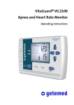
100 %). The result is a Discrete Saturation Transform
(DST™) plot as shown in Fig. 15, where R corresponds
to SpO2 = 97%.
The DST plot has at least one peak, caused by the arterial
pulse. This peak shows, that at the associated SpO2 value
the effective noise cancellation was especially effective,
because a well defined source of noise, the arterial pulse
variation, was identified.
The DST plot may show more peaks with even higher
peak values, caused by other sources of noise (e.g. venous variations of light absorbance). But because venous
44 • Appendix
Operator manual VitaGuard® VG 300
Guarantee conditions
We provide the following guarantee for VitaGuard®:
1. GeTeMed guarantees that all VitaGuard® devices with
the exception of all consumables such as SpO2sensors, batteries and packaging material are free from
faults for one year after delivery. This guarantee is
provided in addition to the statutory warrantee.
2. If a fault develops in the VitaGuard® monitor within
the first year after delivery, GeTeMed will repair or
replace – as GeTeMed decides – the defective monitor
free of charge. The customer must to prove that the
fault showed up within the first year after delivery.
3. To process the guarantee, the customer or distributor
must send the monitor accompanied with the invoice
to GeTeMed. GeTeMed will test the monitor. If no
fault is discovered under the scope of this guarantee,
than the purchaser takes responsibility for the costs of
transport and testing. If GeTeMed decides to replace a
defective device or part of it, then the ownership of the
defective device or component is transferred to
GeTeMed.
4. Intrusions and attempts to repair shall be executed
only by GeTeMed or authorised third parties that have
been certified to do so by GeTeMed. Any warrantee
claim is void if such attempts by non-authorised persons have been performed. The warrantee is also void
if the VitaGuard® monitor or its components have
been improperly handled.
Operator manual VitaGuard® VG 300
Safety and Accuracy • 37
• Loss of the pulse signal can occur if the patient has
hypotension, severe vasoconstriction, severe anaemia
or hypothermia.
• Loss of pulse signal can occur if there is an arterial
occlusion proximal to the sensor.
• Loss of pulse signal can occur if the patient is in cardiac arrest or is in shock.
blood or tissue has ALWAYS a lower SpO2 level these
peaks are always at lower SpO2 values.
Cleaning
• Disconnect sensors and cables from the patient and the
monitor, before cleaning them. Use a damp cloth to
clean both the monitor and the cables. Use cleaning
solution sparingly. Excessive solution can flow into
the monitor and cause damage to internal components.
• Do not use aggressive solvents or cleaning agents such
as petroleum-based or acetone solutions to clean the
monitor. These substances attack the device’s materials and device failure may result.
• Do not use alcohol to clean the monitor or cables as
this hardens the cables.
• Do not touch, press or rub the display panel or casing
with abrasive cleaning compounds, instruments,
brushes, rough-surfaced materials, or bring them into
contact with anything that could scratch them.
• Do not autoclave, pressure sterilise or gas sterilise the
monitor or any of its components.
Regulatory information
• VitaGuard® VG 300 complies with the requirements
of the Medical Device Directive 93/42/EEC.
• VitaGuard® VG 300 fulfils the EMC requirements laid
out under the directive 89/336/EWG and EN60601-12 1/May 1993, part 1.2; EN55011 class B: 1991; DIN
VDE 0875 part 11/07.92.
• VitaGuard® VG 300 is a class IIa devices according to
the Medical Device Directive 93/42/EEC (MDD).
36 • Safety and Accuracy
Operator manual VitaGuard® VG 300
Fig. 15
DST plot of output power vs. SpO2 value
In reverse, The arterial SpO2 value is always given at
the peat with the highest SpO2.
This entire sequence is repeated every 0.4 seconds on the
most recent eight (can be varied between six and 16) seconds of raw data. The MS-3 SpO2 therefore corresponds
to a running average of arterial saturation of arterial haemoglobin saturation that is updated every 0.4 seconds.
Error codes
The Masimo SpO2 module (MS-3 board) incorporated in
VitaGuard® VG 300 communicates with VitaGuard® via
a serial port. Should a failure occur on the module, an appropriate error code is passed to VitaGuard®. These codes
are registered in the compliance log. Should no communication take place between VitaGuard® and the MS-3
module, then code 31 is registered.
Error
code
Meaning
31
No communication with MS-3 board.
32
DSP: Checksum Failure.
33
DSP: Program Memory Test Failure.
34
DSP: Data Memory Test Failure.
35
DSP: Detector ADC Interrupt Failure.
36
DSP: MCU Interrupt Failure.
Operator manual VitaGuard® VG 300
Appendix • 45
Error
code
Meaning
37
38
DSP: Diag Queue Overrun.
DSP: Hardware Status Failure.
39
DSP: Raw (Data) Queue Overrun.
40
DSP: MCU Watchdog Failure.
63
Diagnostic Failure.
Tab. 10
Explanation of the error codes used within VitaGuard® VG 300.
These error codes are intended for maintenance purposes
by qualified personnel only.
Patent information
The following is a (possibly incomplete) table of U.S. issued Patents and Applications and Patent Markings.
No
USA
Patent
Tittle
1 5.337.744 Low Noise Finger Cot Probe
2 5.452.717 Low Noise Finger Cot Probe
3 5.482.036 Signal Processing Apparatus and Method
4 5.490.505 Signal Processing Apparatus
5 5.632.272 Signal Processing Apparatus
6 5.638.818 Improved Low Noise Optical Probe
7 5.645.440 Patient Cable Connector
8 5.685.299 Signal Processing Apparatus
9 5.758.644 Manual and Automatic Probe Calibration
10 5.769.785 Signal Processing Apparatus and Method
11 5.782.757 Low Noise Optical Probes
12 D393.830 Patient Cable Connector
13 5.823.950 Manual and Automatic Probe Calibration
14 pending Improved Low Noise Optical Probe
15 pending Patient Cable Connector
16 pending Improved Signal Processing Apparatus
17 pending Signal Processing Apparatus
18 pending Shielded Medical Connector
19 pending Signal Processing Apparatus
Accuracy and factors effecting the SpO2 measurement
• If you doubt the accuracy of any measurement, first
check the patient’s vital signs by alternate means and
check that the monitor is functioning correctly.
• Inaccurate measurements may be caused by incorrect
sensor application or use.
• Inaccurate measurements or loss of the pulse signal
may be caused by exposure to excessive illumination
such as surgical lamps (especially ones with Xenon
light sources), bilirubine lamps, fluorescent lights, infrared heating lamps, or direct sunlight. Expose to
excessive illumination can be corrected by covering
the sensor with a dark or opaque material.
• Inaccurate measurements may be caused by placing
the sensor on an extremity with a blood pressure cuff,
arterial catheter or intravascular line.
• Loss of the pulse signal can occur if the LNOP® sensor is too tight.
• Use only Masimo LNOP® sensors for SpO2 measurements. Other sensors may cause improper performance.
Information for the handling paediatrician
• A pulse oximeter should be considered an early warning device. As a trend towards patient deoxygenation
is indicated, blood samples should be analysed by a
laboratory co-oximeter to completely understand the
patients condition.
• Inaccurate measurements may be caused by significant levels of dysfunctional haemoglobin (e.g. Carboxyhaemoglobin or Methaemoglobin). Carboxyhaemoglobin may erroneously increase SpO2 readings.
The level of increase is approximately equal to the
amount of Carboxyhaemoglobin present.
• Dyes (e.g. Indocyanine green or methylene blue) or
any substance containing dyes that change the usual
arterial pigmentation may cause erroneous readings or
inaccurate measurements.
• Inaccurate measurements may be caused by venous
pulsation
20 pending Signal Processing Apparatus
46 • Appendix
Operator manual VitaGuard® VG 300
Operator manual VitaGuard® VG 300
Safety and Accuracy • 35
• Electrical shock hazard: Never open or tamper with
the power adapter. Do not use the power adapter if it
has fallen.
• Do not operate the power adapter from an electrical
outlet controlled by a wall switch or dimmer.
• The mains power adapter should not be operated in
damp environments (e.g. bathroom or utility room).
• Remove the batteries when storing the monitor for
longer periods.
• You can check the battery status by pressing
<INFO/ > multiple times. Please follow the procedure explained in 'Battery replacement' on page 22.
No
34 • Safety and Accuracy
Operator manual VitaGuard® VG 300
Tittle
21 pending Method and Apparatus for Demodulating
22 pending Manual and Automatic Probe Calibration
23 pending Method and Apparatus for Demodulating
24 pending Improved Signal Processing Apparatus
25 pending Low Noise Optical Probes
26 pending Signal Processing Apparatus and Method
27 pending Signal Processing Apparatus
28 pending Signal Processing Apparatus
29 pending Photodiode Detector with Integrated Shielding
30 pending Pulse Oximetry Sensor Adapter
31 pending Non-Protruding Optoelectronic Lens
Safety precautions - Sensor and cable
• Only use the SpO2 patient cable delivered with the
monitor.
• Connect the SpO2 sensor to the SpO2 patient cable
(PC08 or PC12) only.
• Only use Masimo SpO2 sensors that have been verified and delivered by GeTeMed or its agents. Carefully read the sensors 'Directions for Use' information.
• Carefully route the cables to reduce the risk of patient
entanglement or strangulation! If necessary, affix the
cables with a plaster or tape.
• Tissue damage can be caused by incorrect application
or use of an LNOP® sensor, for example, by wrapping
the sensor too tightly. Inspect the sensor site as directed in 'Directions for use of LNOP® sensors' on
page 50 to ensure skin integrity and correct positioning and adhesion of the sensor. Detailed instructions
for the different sensor types are given for the LNOP®
sensors DC1 on page 51, Adt on page 55, Pdt on page
59, Neo on page 64 and NeoPt on page 68.
• Do not use damaged LNOP® sensors or cables. Do not
immerse in water, solvents or cleaning agents. Detach
the sensor from the patient before bathing it.
• Do not attempt to sterilise by any means. Do not use
alcohol to clean the cables as this may harden the cable isolation.
USA
Patent
32 pending Patient cable sensor Switch
Patent Marking:
The Masimo-Device incorporated in VitaGuard® is covered
under one or more of the following U.S.A. patents: 5.482.
036, 5.490.505, 5.632.272, 5.685.299, 5.758.644, 5.769.785
and int. equivalents. U.S.A. and international patents pending.
Tab. 11
The most important patents on pulse oximetry issued in the U.S. for Masimo Corp.
External alarm unit EA1000
Operation
The external alarm unit can be connected to VitaGuard®
to amplify the integrated alarm generator. It is intended
for situations where your home is such that you may not
hear the integrated alarm generator reliably.
Verify in your actual situation, if you can hear a possible
Do not cover the
alarm, independently of what you are doing. Think of acspeaker!
tivities like housecleaning, watching TV etc.
®
Caution: Due to the ex- Make sure the alarm speakers of VitaGuard or EA 1000
are not blocked by anything placed on them. You cannot
treme volume of
react properly to an alarm if you cannot hear it!
EA 1000 you should
leave it at least 3 m off Make sure you can react to an alarm within a few
seconds! Remember: YOU, the caretaker, must react
your patient!
on an alarm! The monitor cannot react for you! Refer
also to 'EMERGENCY SITUATION' on page 1 and
'Operation' on page 8.
Operator manual VitaGuard® VG 300
Appendix • 47
Function elements
The unit has a trimmer to regulate the alarm volume.
Once it is connected to VitaGuard® using the cable supplied, it is automatically activated. The three light emitting diodes (LED's) on the unit have the following functions:
LED
•
Meaning
'Monitoring VitaGuard is activated and the EA 1000 is
active' (green, ready. Green flashing = system status
OK! The flashing frequency is independent
flashing)
from the rhythm of the LEDs on VitaGuard®.
'Change bat- The battery is weak and should be exchanged. The remaining capacity at start of
teries'
(red, flashing) flashing is typically sufficient for about two
days. Pay attention to the polarity of the
new battery!
The monitor generated an alarm. A loud
'Alarm'
(red, flashing) flashing tone is generated, which volume
can be varied within some limits.
If none of the LEDs are active, then the monitor is not
switched on or there is no monitor connected at all.
•
•
•
Technical data
item
Value
Battery:
9 V Battery Alkaline Type 6LR61 or
6AM6
Connection
cable:
7,5 m (standard)
Operation
period:
On average about two month
Tab. 12
•
Technical data of the external alarm unit EA 1000.
•
Safety with the external alarm unit
• Caution: Keep the external alarm unit at least 3 m
away from the patient to prevent damage from the
high alarm volume of the EA 1000.
• Pay attention to the polarity when replacing the battery!
• Caution: Do not puncture the speaker because you
could damage it.
48 • Appendix
Operator manual VitaGuard® VG 300
This can easily happen if operated in a tent. If condensation accumulates, wait at least 2 hours before using
the monitor.
Keep the monitor away from devices that produce
strong electromagnetic fields such as televisions,
walkie-talkies, radio transmitters (as found in cordless
telephones and paging transmitters, radio controlled
toys, security equipment in many shops, wireless
communication links for computers and peripherals,
etc.), fluorescent lamps, microwave ovens and so on.
Do not use VitaGuard® near MRI units (magnetic
resonance imaging). Induced currents could potentially cause burns. Also, VitaGuard® may affect the
MRI image and the MRI unit may affect the accuracy
of the VitaGuard® readings.
Do not operate in connection with HF-surgical equipment, defibrillators, TENS units or pacemakers.
Should, however, the monitor still be connected to the
patient during defibrillation, the readings may be inaccurate for a short period afterwards.
While monitoring patients do not connect VitaGuard®
to any devices (e.g. evaluating PC) other than those
delivered with the monitor. Other devices may not
have the required isolation and cause excessive leakage currents (>100uA) to flow through the patient.
This may damage the patient and/or the monitor.
Static electricity from fabrics (e.g. curtains or rugs)
may cause damage to the patient and the monitor or
may reduce the reliability of the monitoring function.
Always touch the patient’s bed or a wall before touching the patient or the monitor. Try to use fabric softener when washing the patient’s clothes to reduce
static electricity.
Do not operate VitaGuard® when travelling by air.
Switch the monitor off and remove the batteries before
packing the monitor into your luggage. Pressure due to
other luggage my otherwise switch the monitor on
during the flight causing the monitor to generate a
technical alarm.
Safety precautions - Power supply
• Only use the mains power adapter NA 2000-2 or the
car power adapter NAK1500.
Operator manual VitaGuard® VG 300
Safety and Accuracy • 33
VitaGuard’s MDD approval is bound to approved accessories!
• Electrical shock hazard: Never open or dismantle the
monitor or any other items delivered with the monitor
e.g. mains power adapter, cable connectors, etc.
• Do not lift VitaGuard® by the power supply cord or
any of the patient cables.
• Do not place VitaGuard® or its power adapter in a position that might cause it to fall onto the patient.
• Do not press heavily on the monitor (press buttons
lightly).
• Do not use damaged components, sensors or cables.
• Do not immerse VitaGuard® or any of its components
in liquids. Detach all sensors from the patient before
bathing.
• VitaGuard® and the authorised accessories can only be
purchased through authorised agents. Order new sensors before you run out! Never use accessories from
other sources!
• Maintenance repairs may only be carried out by
authorised persons.
• Check the acoustic alarm on a weekly basis.
• If an alarm condition occurs while the alarm silence
period is activated (e.g. after pressing a button), the
only alarm indication is the visual red alarm LED.
• Send the monitor back to the manufacturer or agent
for environmental friendly disposal.
Safety precautions - Environment
• Do not operate in the vicinity of explosive gases. Do
not use in the presence of flammable anaesthetics or
other flammable substances in combination with air,
oxygen-enriched environments, or nitrous oxide.
• Do not use in extreme temperatures (below 10°C or
above 40°C). Do not place VitaGuard® near heat
sources such as radiators, ventilators, ovens, etc. and
do not expose it to direct sunlight.
• Neither the monitor nor any of its accessories may be
immersed into liquids. Detach the sensor from the patient before bathing it.
• Do not expose the monitor to sudden temperature or
humidity variations. Humidity changes should not result in condensation accumulating on the monitor.
32 • Safety and Accuracy
Operator manual VitaGuard® VG 300
• Avoid penetration of moisture into the unit.
Pay also attention to the safety precautions for VitaGuard® on page 31ff! These precautions are valid for the
external alarm also!
Car adapter NAK 1500
Operation
The car adapter NAK 1500 can be used to operate a VitaGuard® monitor from the 12V car supply. NAK 1500 is
connected instead of the mains adapter NA 2000-2. It is
fitted with a safety universal plug (DIN ISO 4165), that
fits alternatively into the cigarette lighter or the normal
car socket outlet. A green LED signalises operation from
the car power.
Technical data
item
Value
Input
12 V car power supplies.
Output
+5V DC
max. current
600 mA
Operational
temperature.
10 .. 50 °C (50 .. 122 °F)
Connectors:
Cable:
VitaGuard®: 2pin socket
Car:
safety universal plug
3m
Tab. 13
Technical data of the Car adapter NAK 1500.
Safety with the adapter NAK 1500
• Caution: Operate only on 12V car power supplies!
• To avoid condensation, do not leave the car adapter in
the car overnight.
• The car adapter can be fixed in the car with the attached Velcro tape. It should not be exposed to direct
sunlight or warm air from the cars heating system.
Operator manual VitaGuard® VG 300
Appendix • 49
VI. Directions for use of LNOP® sensors
Following you'll find help in deciding what type of sensor
to use. Following, an adapted copy of the material accompanying every economy-sized package of different
LNOP® sensors is printed.
IV. Safety and Accuracy
Important – Intended
Use:
Sensor selection
GeTeMed offers five different types of LNOP® sensors:
LNOP®-DC1, LNOP®-Adt, LNOP®-Pdt, LNOP®-Neo
and LNOP®-NeoPt.
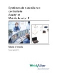
Selection plan
Following you'll find a scheme that might help you to decide what type of sensor to choose:
Patient weighing
< 30 kg ?
Yes
No
Patient weighing
< 1 kg ?
LNOP NeoPt
Yes
long-term
monitoring?
LNOP Adt
Yes
No
Patient weighing
< 10 kg ?
LNOP Neo
Yes
LNOP Pdt
No
Fig. 16
LNOP DC1
LNOP Adt
No
Plan to choose the optimal sensor type.
After choosing the right sensor you may read the appropriate sensor instructions. You'll find the manuals for the
LNOP® DC1 hereafter, for the LNOP® Adt on page 55,
for the LNOP® Pdt on page 59, for the LNOP® Neo on
page 64 and for the LNOP® NeoPt on page 68.
50 • Directions for use of LNOP® sensors
Operator manual VitaGuard® VG 300
VitaGuard® is designed to monitor pulse rate and oxygen
saturation. Should a bradycardia alarm (low pulse rate) or
a drop in the arterial oxygen saturation occur, then artificial respiration and cardiopulmonary resuscitation (CPR)
measures may need to be taken. Therefore, allow a
trained person to demonstrate to you how you should perform these measures..
Safety precautions
Safety precautions - Usage
• VitaGuard has no therapeutic intentions. YOU, the
caregiver, must act in the event of an emergency.
• Never leave the patient alone until you have verified that the monitor is working properly!
• Never continue operating a damaged or unreliable
monitor! Immediately check the vital signs of the patient! Send the monitor back to the manufacturer or
agent for inspection! Watch the patient yourself until
you got another monitor or your handling physician
advises you to stop monitoring.
• Verify that you can hear a possible alarm independent
of where you are and what you are doing. Make sure
that VitaGuard’s alarm speaker is not blocked by anything laid on top of the monitor. You cannot act
promptly to an alarm if you do not hear it!
Stay near your patient! • Make sure you can act on an alarm within a few
seconds!
• VitaGuard® must be demonstrated to you by a qualified person. Do not operate the monitor until you have
been made familiar with its usage by a trained person
and have read and understood this manual and all
other documentation provided.
• Allow your doctor to set the alarm limits and monitorImportant!
ing parameters suitable for your patient.
• VitaGuard® may not be used for other purposes other
than the intended purpose laid out in 'Intended use of
VG 300' on page 5.
YOU must act on
alarms!
Operator manual VitaGuard® VG 300
Safety and Accuracy • 31
LNOP® DC1 - Directions for use
Pulse oximetry
Item
Value range
Pulse rate
25 – 240 BPM
Lower alarm limit
25, 30, 35, ... 175, 180 BPM
Upper alarm limit
100, 105, 110, ... 235, 240 BPM
Pulse rate accuracy:
(± 1 Std. Dev.) *
± 3 digits during no motion conditions ± 5 digits during motion conditions
SpO2 range
1 – 100 %
SpO2 accuracy:
(± 1 Std. Dev.)*
Range above 70 % - ± 3 digits on
neonates during motion.
Range 0 % - 69% unspecified
* Testing based on adult volunteers in induced hypoxia studies with LNOP®-Adt sensors in the range 70 – 100% SpO2
against a laboratory co-oximeter and ECG monitor.
Tab. 7
Pulse rate monitor properties of VitaGuard®
VG 300.
Miscellaneous
Item
Value range
MDD classification IIa
Safety classification BF (IEC 601-2-25)
IP41 (IEC 601-1)
Operating tempera- 10 - 40 Celsius
ture
Humidity
Tab. 8
0 – 90 %, non condensing
Miscellaneous properties of VitaGuard® VG 300.
Fig. 17
Instructions for LNOP® DC1 SpO2 sensors.
These sensors are intended for multiple use on different
patients weighing > 30 kg. They are non sterile and latex
free and can not be sterilised.
INDICATIONS/CONTRAINDICATIONS
The LNOP DC1, Reusable Adult Sensor is indicated for
either “spot check” or continuous non-invasive monitoring of arterial oxygen saturation (SpO2) and pulse rate for
patients weighing >30 kg. It is for use only with instruments containing Masimo SET oximetry or licensed to
use LNOP sensors. Consult individual instrument manufacturer for compatibility of particular instrument and
sensor models. Each instrument manufacturer is responsible for determining whether its instruments are compatible with each sensor model.
The LNOP DC1 is contraindicated for use on mobile patients or for prolonged periods of use. It is not intended
for long-term monitoring. It must be removed and repositioned to a different monitoring site at least every four (4)
hours. If extended monitoring is required, use of a LNOP
Adt adhesive sensor is recommended.
INSTRUCTIONS
A) Site Selection
• Choose a site that is well perfused and least restricts a
conscious patient’s movements. The ring finger of the
non-dominate hand is preferred.
• Alternatively, the other digits on the non-dominate
hand may be used. Always choose a site that will
completely cover the sensor’s detector window. The
great toe or long toe (next to the great toe) may be
30 • Technical Data
Operator manual VitaGuard® VG 300
Operator manual VitaGuard® VG 300
Directions for use of LNOP® sensors • 51
used on restrained patients or patients whose hands are
unavailable.
• Site should be cleaned of debris prior to sensor placement.
III. Technical Data
General
B) Attaching the Sensor to the Patient
1. Open the sensor by pressing on hinge tabs. Place the
selected digit over the sensor window of the LNOP
DC1. The fleshiest part of the digit should be covering
the detector window in the lower half of the sensor.
The top half of the sensor is identified by the cable.
On finger sites, the tip of the finger should touch the
raised digit stop inside the sensor. If the fingernail is
long, it may extend over and pass the finger stop (Fig.
18).
Item
Value range
Weight
750g (with batteries)
Dimensions
(13,5 x 19 x 4,5) cm3
Batteries
4 x 1,5 V (Type LR6, AA), alkaline
Battery operation
min. 2 hours* with SpO2 monitoring
Key panel
Washable buttons
Battery indicator
Flashing message
Battery exhaustion
Warn tone
Mains supply
External power adapter NA 2000-2
with FRIWO FW1299 (5Volt, 900
mA, DC)
LED's and LCD graphical display
Display elements
Fig. 18
Patient cable
Masimo patient cable PC08, length
2.44m
Test and maintenance period
A maintenance procedure
is required every 18
months. The end of the
maintenance period is
marked with a sticker.
DC1 sensor placement
2. The hinged tabs of the sensor should open to evenly
distribute the grip of the sensor along the length of the
finger (Fig. 19). Check position of sensor to verify
correct positioning. Complete coverage of the detector
window is needed to ensure accurate data.
*
Only with batteries VARTA ALKALINE Extra Longlife!
Tab. 5
General properties of VitaGuard® VG 300.
Memory
Fig. 19
Orientation of emitter and detector
3. Orient the sensor so that the cable will be running towards the top of the patient’s hand (as shown in Fig.
20). Connect the LNOP DC1 connector to a patient
cable.
52 • Directions for use of LNOP® sensors
Operator manual VitaGuard® VG 300
Item
Value range
Capacity
200 episodes
Duration
approx. 7 hours
Storage mode
Event or permanent
Pre-alarm storage
10 - 60 seconds
Post-alarm storage
10 - 60 seconds
Interface
RS232 interface
Software option
VitaGuard® for Windows – Software
program for evaluation of stored data
Tab. 6
Memory properties of VitaGuard® VG 300.
Operator manual VitaGuard® VG 300
Technical Data • 29
Monitor log:
In VitaGuard® for Windows one can display an Overview over the monitoring period (Monitor log: (Fig. 13).
Here the monitoring took place only during the night
with short interrupts around midnight and in the early
morning.
The main screen (Fig. 14) shows the context of the actual
episode for the pulse frequency and the plethysmogram.
Fig. 20
Correctly attached sensor
NOTE: With smaller digits, in order to completely cover
the detector window, the digit might not need to be
pushed all the way to the stop. The sensor is not intended
for use on the thumb or across a child’s hand or foot.
Fig. 13
Easy but complex
documentation for the
patient bulletin.
VitaGuard® for Windows: Monitor protocol
VitaGuard® for Windows supports the documentation
of the monitoring behaviour and results. One can generate and print many overviews and tables.
C) Attaching the Sensor to the Patient Cable
1. Orient the connecting tab so that the “shiny” contacts
are facing up and mate the logo to the logo on the patient cable (Fig. 21). Insert the LNOP DC1 connector
over the patient cable connector until there is a tactile
or audible click of connection.
Fig. 21
Connecting patient cable and sensor
2. Gently tug on the connectors to ensure a positive contact. Tape may be used to secure the cable to the patient for ease of movement.
D) Disconnecting sensor and patient cable
1. Place thumb and index finger on grey buttons on either side of the patient cable connector (Fig. 22).
2. Press firmly on the grey buttons and pull to remove
the sensor.
CLEANING
Fig. 14
28 • Operating VitaGuard®
®
Main screen of VitaGuard for Windows; Bradycardia-episode
Operator manual VitaGuard® VG 300
To clean the sensor, first remove it from the patient and
disconnect it from the patient cable. You my then clean
the LNOP DC1 by wiping it with a 70% isopropyl alcohol pad. Allow the sensor to dry prior to placement on a
patient.
Operator manual VitaGuard® VG 300
Directions for use of LNOP® sensors • 53
Caution: Do not soak or immerse the cable in any liquid
solution. Do not attempt to sterilise.
Episode memory and PC interface
Integrated memory for
100 alarm episodes.
Fig. 22
Disconnecting patient cable and sensor
WARNINGS
• The site must be checked and changed at least every
four (4) hours
NOTE: Exercise extreme caution with poorly perfused patients; skin erosion and pressure necrosis can
be caused when sensors are not frequently moved. Assess the site at least every two (2) hours with poorly
perfused patients.
• If the sensor is damaged in any way, discontinue use
immediately.
• To prevent damage, do not soak or immerse the sensor
in any liquid solution. Do not attempt to sterilise.
• Intravascular dyes may lead to inaccurate SpO2 measurements.
• Elevated levels of Carboxyhaemoglobin (COHb) may
lead to inaccurate SpO2 measurement.
• Elevated levels of Methaemoglobin (MetHb) will lead
to inaccurate SpO2 measurements.
• Failure to apply the LNOP DC1 properly may cause
incorrect measurements.
• Do not use the LNOP DC1 during MRI scanning.
• Avoid placing the LNOP DC1 on any extremity with
an arterial catheter or blood pressure cuff.
• The pulsation’s from intra-aortic balloon support can
be additive to the pulse rate on the oximeter pulse rate
display. Verify pulse rate against an ECG heart rate.
• Avoid bending and distorting the sensor cable, because this may damage the sensor.
Hint: If the monitor displays pulse rate and SpO2 not
constantly than check the sensor placement and reposition
54 • Directions for use of LNOP® sensors
Operator manual VitaGuard® VG 300
Event mode is default!
Stored data can be reviewed on a PC.
VitaGuard® is fitted with a solid-state memory for storing
alarm episodes. The pulse rate, SpO2 and plethysmograph
are stored as a function of time. Up to approx. 7 hours of
data (or 200 episodes) can be stored with the standard
memory.
There are two storage modes possible - event mode or
permanent mode. When, in event mode, an alarm occurs,
both time and date as well as the signal curves for a programmable period prior to the alarm (usually 50s), during
the alarm phase and for a programmable period after the
alarm (usually 20s) are stored together as an alarm episode. In the permanent mode of operation, all the signals
are continuously stored in blocks of approx. 2.5 minutes,
regardless of whether an alarm occurs or not.
When the monitor is switched on, it always assumes
event mode storage. To change to permanent storage
mode, enter the expert mode and change the memory
mode option under the 'System settings' menu. Refer also
to 'System settings main menu:' on page 24.
In both modes, the memory operates as a loop memory
i.e. when the memory is full (200 episodes), the oldest
episodes are automatically deleted to make room for new
ones. This ensures that the most actual stored episodes
are available.
The actual memory usage is displayed during start-up of
the monitor. It can be reviewed by pressing <INFO/ >
multiple times.
The data from the monitor can be transferred to a standard PC over the serial RS232 interface and evaluated
with a Windows based programme developed by GeTeMed. The PC programme can also be used to set the
monitor internal clock
GeTeMed developed the Software VitaGuard® for
Windows to support the evaluation of the saved protocols
and alarm episodes. VitaGuard® for Windows runs on
Windows 95, 98, NT 4.0 or higher. It is sold only to
authorised dealers and to physicians that supervise users
of VitaGuard®.
Operator manual VitaGuard® VG 300
Operating VitaGuard® • 27
post-alarm period (usually 20s) to elapse before you can
view the information about an alarm that has just occurred. The actual process of saving is displayed.
Alarm types
Bradycardia
Tachycardia
SpO2 low
SpO2 high
SpO2
Silent
Silent Brady.
Silent Tachy.
Permanent
Manual
Combination
The following alarm types can be displayed under status
information:
Pulse rate below the set alarm limit.
Pulse rate above the set alarm limit.
SpO2 below the set alarm limit.
SpO2 above the set alarm limit.
Episode with an overrun of both SpO2 limits.
Silent alarm where the SpO2 lay outside either of the silent alarm limits.
Pulse rate below the silent alarm limit.
Pulse rate above the silent alarm limit.
Episode without an alarm stored in permanent mode.
Episode manually initiated.
Episode with more than one alarm cause e.g. SpO 2 and
bradycardia together.
it, if necessary. If this does not help than change the sensor.
Hint: Sensors being used for a long period tend to reduced performance. A sensor should be replaced, if pulse
rate and SpO2 become questionable.
SPECIFICATIONS
When used with Masimo SET pulse oximetry monitors or
with licensed Masimo SET pulse oximetry modules, using PC Series patient cabled, during no motion, the accuracy of the LNOP DC1 from 70% to 100% SpO2 is ± 2
digits (± 1 Std. Dev.).
Please see also 'Miscellaneous Warnings and Hints' on
page 73ff!
LNOP® Adt - Directions for use
Fig. 23
Instructions for LNOP® Adt SpO2 sensors.
These sensors are intended for multiple use on only one
patient weighing > 30 kg. They are non sterile and latex
free and can not be sterilised.
INDICATIONS/CONTRAINDICATIONS
The LNOP Adt, adult Adhesive Sensor is indicated for
single-patient use for the continuous non-invasive monitoring of arterial oxygen saturation (SpO2) and pulse rate
for patients weighing >30 kg. The LNOP Adt is or use
only with instruments containing Masimo SET oximetry
or licensed to use LNOP sensors. Consult individual oximetry system manufacturer for compatibility of particular
instrument and sensor models. Each instrument manufacturer is responsible for determining whether its instruments are compatible with each sensor model.
26 • Operating VitaGuard®
Operator manual VitaGuard® VG 300
Operator manual VitaGuard® VG 300
Directions for use of LNOP® sensors • 55
The LNOP Adt is contraindicated for patients who exhibit allergic reactions to adhesive tape. The sensor must
be removed and the site inspected at least every eight (8)
hours and, if indicated by circulatory condition or skin integrity, reapplied to a different monitoring site.
INSTRUCTIONS
A) Site Selection
• Choose a site that is well perfused and least restricts a
conscious patient’s movements. The ring or middle
finger of the non-dominate hand is preferred.
• Alternatively, the other digits on the non-determinate
hand may be used. Always choose a site that will
completely cover the detector window. The great toe
or long toe (next to the great toe) may be used on restrained patients whose hands are unavailable.
• The site should be cleaned of debris and dry prior to
sensor placement.
B) Attaching the Sensor to the Patient
1. Open the pouch and remove the sensor. Holding the
sensor with the printed side down, bend the sensor
backward and remove the backing. Orient the sensor
so the detector can be placed first (Fig. 24). Press the
detector onto the fleshly part of the finger near the tip
of the finger. Press down the “T” shaped adhesive
ends of the sensor onto the finger (Fig. 25).
Fig. 24
Sensor placement; detector on the finger tip
Time/Date main menu:
See also 'Explanation of These settings can be changed using <MODE/Esc>. Refer also to 'Monitor display structure' and 'Monitor menu
the menu settings' on
structure' on pages 12 and 13. The different settings are
page 38!
explained in detail in 'Explanation of the menu settings'
on page 38.
Item
Value range
Day (num.)
1, 2, ... 29, 30 (31).
Month
January, February, March etc.
Year
1998, 1999, etc.
Hour
0, 1, ... 22, 23.
Minute
0, 1, ... 58, 59.
Tab. 4
Value range for the time settings main menu
Status memory function
Using <STATUS/Enter>, the stored episodes
can be examined in
chronological order. By
pressing the key once,
information about the
last stored episode is displayed. Using the arrow
buttons, other episodes
can be addressed. To obtain more information
about a particular episode, press <STATUS/Enter> again. After the
alpha-numerical
information you will see
the stored signals. Press
<MODE/Esc> to exit the
episode information
mode.
Standard display 1
<ALARM/Stop>
Standard display 2
<Status>
Episode number / count
Type of episode
Date and time
Duration
<∆> / <∇>
to choose
<Status>
Settings at the alarm
<Status>
Pulse oximeter settings
and SpO2 limits
at the alarm
<Status>
Heart rate information at the alarm
<Status>
Plethysmogram
at the alarm
Fig. 12
Fig. 25
Fixing of the detector
56 • Directions for use of LNOP® sensors
Operator manual VitaGuard® VG 300
Scheme on how to review stored data
Remember that you need to wait for the programmed
Operator manual VitaGuard® VG 300
Operating VitaGuard® • 25
System settings main menu:
See also 'Explanation of These settings can be changed using <MODE/Esc>. Refer also to 'Monitor display structure' and 'Monitor menu
the menu settings' on
structure' on pages 12 and 13. The different settings are
page 38!
explained in detail in 'Explanation of the menu settings'
on page 38.
The factory defaults are shown in large bold font:
Item
Value range
Clear trends
No / yes
SpO2 perfusion
Low_Perfusion On /
Low_Perfusion Off
SpO2 average
6, 8 ... 14, 16 seconds
LCD power save
Off / On
LCD brightness
Level 1, 2, 3, 4
2. Next, wrap the sensor with the emitter (*) and finger
design over the fingernail and secure the wings down
one at a time around finger (Fig. 26). When properly
applied, the emitter and the detector should be vertically aligned as shown (Fig. 27). Check position of
sensor to verify correct positioning and reposition if
necessary. Complete coverage of the detector window
is needed to ensure accurate measurements.
Fig. 26
Fixing of the emitter
Fig. 27
Correctly attached sensor: emitter and detector
are aligned!
Only available in expert mode:
Wave display
Off / On
Silent alarms
No / Yes
Buzzer frequency
2048 Hz / 4096 Hz
Delete memory
No / Yes
Pre-alarm time
10, 20, ... 50, 60 seconds
Post-alarm time
10, 20, ... 50, 60 seconds
Memory mode
Event / Permanent
No / Yes
No / Yes
Ring memory
Load defaults
Tab. 3
Value range for the items in the system settings
main menu
Expert mode main menu:
3. The connector tab is now oriented on the top side of
the patient’s finger so that the “shiny” contacts are
facing up. Mate the logo on the sensor to the logo on
the patient cable. Insert the patient cable into the sensor tab until there is a tactile or audible click of connection (Fig. 28). Gently tug on the connectors to ensure a positive contact. If required, tape may be used
to secure the cable to the patient.
See also 'Explanation of The expert mode can be activated using <MODE/Esc>.
Refer also to “Monitor display structure” and “Monitor
the menu settings' on
menu structure” on pages 12 and 13.
page 38!
Item
Value range
Code word
Enter code word
Fig. 28
24 • Operating VitaGuard®
Operator manual VitaGuard® VG 300
Connecting patient cable and sensor
Operator manual VitaGuard® VG 300
Directions for use of LNOP® sensors • 57
C) Reattachment
The sensor may be reapplied to the same patient if the
emitter and detector windows are clear and the adhesive
still adheres to the skin.
NOTE: Prior to reattachment or rejuvenation, disconnect
the sensor from the sensor cable.
• The adhesive can be partially rejuvenated by wiping
with a 70% isopropyl alcohol pad and allowing the
sensor to thoroughly air dry prior to replacement on
the patient.
• If the adhesive can not be adequately rejuvenated, use
a new sensor.
D) Disconnecting Sensor and Patient Cable
1. Place thumb and index finger on grey buttons on either side of the patient cable (Fig. 29).
The monitor settings and stored alarm episodes are not
lost when changing the batteries. Refer also to 'Technical
Data' on page 29 for battery operation lifetime.
Mains adapter
Only use the mains adapter NA 2000-2 provided with
the monitor. Other mains adapters may not fulfil the
necessary safety standards and could cause serious damage to both the patient and the monitor. When VitaGuard® is operated from the mains adapter, the display
backlight is automatically switched on.
Integrated menus
Monitor settings main menu:
See also 'Explanation of These settings can be changed using <MODE/Esc>. Refer also to 'Monitor display structure' and 'Monitor menu
the menu settings' on
structure' on pages 12 and 13. The different settings are
page 38!
explained in detail in 'Explanation of the menu settings'
on page 38.
The factory defaults are shown in large bold font:
Item
Value range
Lower HR limit
30, 35, ... 80, ... 175, 180 BPM
2. Press firmly on the grey buttons and pull to remove
the sensor.
Upper HR limit
100, 105, ... 220, ... 255, 260 BPM
Lower SpO2 limit
50, 51, ... 88 ... 99, 100 %
WARNINGS
Upper SpO2 limit
50, 51, ... 99, 100 %
• The site must be checked and changed at least every
eight (8) hours
NOTE: Exercise extreme caution with poorly perfused patients; skin erosion and pressure necrosis can
be caused when sensors are not frequently moved. Assess the site at least every two (2) hours with poorly
perfused patients.
• If the sensor is damaged in any way, discontinue use
immediately.
• To prevent damage, do not soak or immerse the sensor
in any liquid solution. Do not attempt to sterilise.
• Intravascular dyes may lead to inaccurate SpO2 measurements.
only available in expert mode:
Silent lower HR
30, 35, ... 50, ... 175, 180 BPM
Fig. 29
Disconnecting patient cable and sensor
58 • Directions for use of LNOP® sensors
Operator manual VitaGuard® VG 300
Silent upper HR
100, 105, ... 255, 260 BPM
Silent lower SpO2
50, 51, ... 88 ... 99, 100 %
Silent upper SpO2
50, 51, ... 99, 100 %
Bradycardia delay
4, 5, 6, ... 14, 15 seconds
Tachycardia delay
4, 5, ... 15, ... 23, 24 seconds
SpO2 lower delay
1, 2, ... 6, ... 19, 20 seconds
SpO2 upper delay
1, 2, ... 6, ... 19, 20 seconds
Tab. 2
Value range for the items in the monitor settings
main menu
Operator manual VitaGuard® VG 300
Operating VitaGuard® • 23
fore, always insert batteries, even if you use the mains
adapter supplied with the monitor.
Battery replacement
Important! Check batteries with active SpO2
module!
Replacing batteries:
Switch the monitor off before replacing the batteries.
To test that the batteries in the battery compartment are
charged enough for SpO2 operation, carry out the follow
steps:
− Remove the external power adapter so that the device
is powered from batteries.
− Wait 30 seconds and then press <INFO/∆> a number
of times until you reach the battery information.
− If the state of the batteries is not good, replace them
immediately with good-quality alkaline batteries such
as VARTA alkaline Extra Longlife. It is recommended that you always keep at least two spare sets handy.
Slide open the battery compartment at the back of the
monitor. Pay attention to the polarity of the batteries
when inserting the new ones(Fig. 11).
Please pay attention to
the polarity of the batteries as shown on the
bottom of the battery
compartment.
• Elevated levels of Carboxyhaemoglobin (COHb) may
lead to inaccurate SpO2 measurement.
• Elevated levels of Methaemoglobin (MetHb) will lead
to inaccurate SpO2 measurements.
• Failure to apply the LNOP Adt properly may cause incorrect measurements.
• Do not use the LNOP Adt during MRI scanning.
• Avoid placing the LNOP Adt on any extremity with
an arterial catheter or blood pressure cuff.
• The pulsation’s from intra-aortic balloon support can
be additive to the pulse rate on the oximeter pulse rate
display. Verify pulse rate against an ECG heart rate.
• Avoid bending and distorting the sensor cable, because this may damage the sensor.
Hint: If the monitor displays pulse rate and SpO2 not
constantly than check the sensor placement and reposition
it, if necessary. If this does not help than change the sensor.
Hint: Sensors being used for a long period tend to reduced performance. A sensor should be replaced, if pulse
rate and SpO2 become questionable.
SPECIFICATIONS
When used with Masimo SET pulse oximetry monitors or
with licensed Masimo SET pulse oximetry modules, using PC Series patient cabled, during no motion, the accuracy of the LNOP Adt from 70% to 100% SpO2 is ± 2
digits (± 1 Std. Dev.).
Please see also 'Miscellaneous Warnings and Hints' on
page 73ff!
LNOP® Pdt - Directions for use
Fig. 11
Bottom of the monitor with partially opened Battery
compartment.
GeTeMed recommends Only use new, good-quality alkaline LR6 (AA) 1,5V batteries. Change the whole set of batteries. Never use new
ALKALINE Extra
and old batteries together!
Longlife Batteries.
Hint:
Cheap non-alkaline batteries may lead to a drastic reduction in the battery operation time. Some batteries only
have 10-15% of the capacity of good batteries.
22 • Operating VitaGuard®
Operator manual VitaGuard® VG 300
Fig. 30
Instructions for LNOP® Pdt SpO2 sensors.
Operator manual VitaGuard® VG 300
Directions for use of LNOP® sensors • 59
These sensors are intended for multiple use on only one
patient weighing between 10 and 50 kg. They are non
sterile and latex free and can not be sterilised.
INDICATIONS/CONTRAINDICATIONS
The LNOP Pdt, Paediatric/Slender Digit Adhesive Sensor
is indicated for single patient use for the continuous noninvasive monitoring of arterial oxygen saturation (SpO2)
and pulse rate for patients weighing between 10 and 50
kg. It is for use only with instruments containing Masimo
SET oximetry or licensed to use LNOP sensors. Consult
individual instrument manufacturer for compatibility of
particular instrument and sensor models. Each instrument
manufacturer is responsible for determining whether its
instruments are compatible with each sensor model.
The LNOP Pdt is contraindicated for patients who exhibit
allergic reactions to adhesive tape. The sensor must be
removed and site inspected at least every eight (8) hours
and, if indicated by circulatory condition or skin integrity,
reapplied to a different monitoring site.
INSTRUCTIONS FOR USE
A) Site Selection
• Choose a site that is well perfused and least restricts a
conscious patient’s movements. The ring or middle
finger of the non-dominate hand is preferred.
• Alternatively, the other digits on the non-dominate
hand may be used. Always choose a site that will
completely cover the sensor’s detector window. The
great toe or second toe (next to the great toe) may be
used on restrained patients or patients whose hands are
unavailable.
• The site should be cleaned of debris and dry prior to
sensor placement.
B) Attaching the Sensor to the Patient
1. Open the pouch and remove the sensor. Holding the
sensor with the tan printed side downward, bend the
sensor backward and remove the backing from the
sensor. Orient the sensor so the detector can be placed
first (Fig. 31). Press the detector onto the fleshly part
of the finger near the tip of the finger. Press down the
“T” shaped adhesive ends of the sensor onto the finger
(Fig. 32).
60 • Directions for use of LNOP® sensors
Operator manual VitaGuard® VG 300
Bear in mind that you should be able to reach your
patient within 10 seconds in order to react promptly
to a critical situation!
Battery operation
Important Hint:
VitaGuard® can be operated either with four LR6 alkaline
batteries or with an external power adapter (NA 2000-2
or NAK 1500; see 'Power supply' on page 6). The monitor also has an internal battery that always powers the internal memory and clock chip. Should the power adapter
be suddenly removed from the monitor during operation
and no batteries are installed, then the internal battery is
used to generate a warn tone. This should be avoided!
The monitor must be returned to the manufacturer if the
internal battery becomes weak.
Battery supervision
Once the installed batteries become weak, the monitor
displays an appropriate message. This message is displayed after the initialisation phase when VitaGuard® is
switched on and can be checked at any time using
<INFO/∆>. When the batteries become very weak, a
message is repeatedly displayed for 2 seconds every 16
seconds informing you to replace them.
Attention: Monitoring If the external power adapter is not connected and the
is aborted when batter- batteries become weak, the SpO2 module is automatically
switched off. The monitor generates a technical alarm to
ies are weak!
warn the clinician and displays an appropriate message.
Once new batteries have been inserted into the unit or the
external power adapter is reconnected, the SpO2 module
is automatically restarted and monitoring is continued.
Bear in mind, that without monitoring, critically
situations may not be brought to your attention!
You should replace the batteries as soon as possible having seen the message on the display. GeTeMed recommends that you always have at least two spare sets of
batteries at hand!
With low batteries you If the batteries are not replaced and are used further, the
monitor will generate a technical alarm tone forcing you
should firstly restore
to replace the batteries (See Switching VitaGuard® on and
power supply!
off' on page 11).
Remember that the system can only operate in the event
of a mains power failure if batteries are inserted. ThereOperator manual VitaGuard® VG 300
Operating VitaGuard® • 21
ing of all settings is explained in 'Explanation of the
menu settings' on page 38.
YOU must react to
alarms!
Alarms
The monitor generates an alarm if the detected pulse rate
falls for at least a given period below the lower limit or
rises above the upper limit. Then the red LED flashes accompanied by a loud acoustic warning. The LCD displays a message about the actual type of alarm. The alarm
can be stopped by pressing <ALARM/Stop>. Go to your
patient immediately and verify the situation! Both the
alarm setting and the alarm LED will flash in intervals of
1 second to indicate that an alarm has occurred. If no
alarm occurs or if no button is pressed for 5 minutes, the
standard display is deactivated and a message 'monitoring
activated' will appear. The alarm LED will keep flashing
to indicate that an alarm had occurred and will stop once
<ALARM/Stop> is pressed. To obtain information about
the alarm, press <STATUS/Enter>.
Should two alarms occur within the period of one minute,
the alarm will not automatically cease. To stop the acoustic alarm, press <ALARM/Stop>.
System check
Alarm generator
Fig. 31
Sensor placement; detector on the finger tip
Fig. 32
Fixing of the detector
2. Next, wrap the sensor with the emitter (*) and finger
design over the fingernail and secure the wings down
one at a time around finger (Fig. 33). When properly
applied, the emitter and the detector should be vertically aligned as shown in (Fig. 34). Check position of
sensor to verify correct positioning and reposition if
necessary. Complete coverage of the detector window
is needed to ensure accurate measurements.
Approximately 4 seconds after switching on the monitor,
the monitor generates a short acoustic signal. Remember
to listen for this tone each time you switch the monitor
on. Should this signal not occur, return the monitor immediately to the manufacturer for inspection. Contact
your supplier to get a replacement monitor. Never continue to use a faulty device!
Baby phone
Important Hint:
Before relying on any form of external system for transmitting the alarm tone to another room (e.g. Baby phone),
ensure that the VitaGuard® alarm tone is transmitted
clearly.
To amplify the alarm signal over a greater distance, we
recommend that you use the external alarm unit EA 1000.
This unit also checks that the monitor is switched on.
20 • Operating VitaGuard®
Operator manual VitaGuard® VG 300
Fig. 33
Fixing of the emitter
Fig. 34
Correctly attached sensor: emitter and detector
are aligned!
Operator manual VitaGuard® VG 300
Directions for use of LNOP® sensors • 61
3. The connector tab is now oriented on the top side of
the patient’s finger so that the “shiny” contacts are
facing up. Mate the logo on the sensor to the logo on
the patient cable. Insert the patient cable into the sensor tab until there is a tactile or audible click of connection (Fig. 35). Gently tug on the connectors to ensure a positive contact. If required, tape may be used
to secure the cable to the patient.
C) Reattachment
The sensor may be reapplied to the same patient if the
emitter and detector windows are clear and the adhesive
still adheres to the skin.
Fig. 35
Connecting patient cable and sensor
NOTE: Prior to reattachment or rejuvenation, disconnect
the sensor from the sensor cable.
• The adhesive can be partially rejuvenated by wiping
with a 70% isopropyl alcohol pad and allowing the
sensor to thoroughly air dry prior to replacement on
the patient.
• If the adhesive can not be adequately rejuvenated, use
a new sensor.
D) Disconnecting Sensor and Patient Cable
3. Place thumb and index finger on grey buttons on either side of the patient cable (Fig. 36).
4. Press firmly on the grey buttons and pull to remove
the sensor.
Fig. 36
Technical alarm and
common reasons:
Disconnecting patient cable and sensor
62 • Directions for use of LNOP® sensors
Operator manual VitaGuard® VG 300
LED will flash in intervals of 1 second to indicate that an
alarm has occurred.
Should two alarms occur within the period of one minute,
the alarm will not automatically cease. To stop the acoustic alarm, press <ALARM/Stop>.
The upper alarm limit can be deactivated by setting the
upper limit value to 100%.
A technical alarm will be generated if the sensor is not
properly connected to the monitor. In this case, a message
is displayed telling the cause of the alarm. The SpO2
value is zeroed out until the problem has been resolved.
The main causes of technical alarms are:
• Bad positioning of the sensor (emitter and detector not
placed across from each other).
• Sensor has fallen off the patient or the patient cable is
not connected to the monitor.
• Excessive movement.
• Too much ambient light or electrical interference from
an external source.
• Batteries are too weak for SpO2 operation.
The LNOP®-sensors as well as the SET®-Technology are
specially invented to handle those problematic situations.
In normal domestic situations the most common source of
technical alarms is bad sensor placement.
Pulse rate
Pulse rate alarm limits: The standard pulse rate alarm limit settings are:
Important:
Lower limit:
80 BPM
Upper limit:
220 BPM
Those settings are suitable for children. When monitoring adults, consult your clinician for appropriate values.
Do not change the alarm limits without prior consultation.
The selected values are displayed on the monitor LCD. If
the pulse rate rises above the upper limit or falls below
the lower limit, then an alarm will be generated. The delays before an alarm is generated are programmable.
Generally, the upper limit needs to be exceeded for at
least 15 seconds and the lower limit for at least 6 seconds
before an alarm takes place.
For instructions on how to change the alarm parameters
refer to 'Monitor display structure' on page 12. The mean-
Operator manual VitaGuard® VG 300
Operating VitaGuard® • 19
WARNINGS
Monitoring
Having connected the SpO2 sensor and ensured that all
connections are secure, switch on the monitor using the
<ON/OFF>-button.
If false alarms occur you must check the sensor placeIf problems arise you
may reposition the sen- ment and the quality of the used sensor.
Do not change any alarm limits to combat alarms
sor!
without prior consultation with your clinician!
Setting alarm parameters
Important:
Ask your doctor to set the alarm limits that suit the
patient. Do not change the alarm limits without prior
consultation.
SpO2 parameters
SpO2 alarm limits:
The standard SpO2 alarm limits are:
Lower limit:
88 %
Upper limit:
100 %
To change the alarm limits, press <MODE> to enter the
main menu structure. Select the 'Monitor settings' menu
using <STATUS/Enter>. Move to the SpO2 alarm limit
menus with the arrow keys and select the required menu
using <STATUS/Enter>. Remember to hold
<ALARM/Stop> when selecting the new value. Press
<STATUS/Enter> to accept the new value or
<MODE/Esc> to reject. The limits may be adjusted between 50% and 100%. Refer to 'Monitor display structure' on page 12. The meaning of all settings is explained
in 'Explanation of the menu settings' on page 38.
Should excessive false alarms occur, check that the sensor is properly connected. Allow a nurse or doctor to
show you how to apply the sensor properly.
Alarms
YOU must act on
alarms!
If the displayed SpO2 value falls below the lower alarm
limit or rises above the upper alarm limit, VitaGuard®
VG 300 will generate an alarm and display an appropriate
message. You should go immediately to the patient and
check its condition. If the SpO2 value moves back within
the set limits, the alarm will automatically cease. The exceeded alarm limit on the LCD display and the alarm
18 • Operating VitaGuard®
Operator manual VitaGuard® VG 300
• The site must be checked and changed at least every
eight (8) hours
NOTE: Exercise extreme caution with poorly perfused patients; skin erosion and pressure necrosis can
be caused when sensors are not frequently moved. Assess the site at least every two (2) hours with poorly
perfused patients.
• If the sensor is damaged in any way, discontinue use
immediately.
• To prevent damage, do not soak or immerse the sensor
in any liquid solution. Do not attempt to sterilise.
• Intravascular dyes may lead to inaccurate SpO2 measurements.
• Elevated levels of Carboxyhaemoglobin (COHb) may
lead to inaccurate SpO2 measurement.
• Elevated levels of Methaemoglobin (MetHb) will lead
to inaccurate SpO2 measurements.
• Failure to apply the LNOP Pdt properly may cause incorrect measurements.
• Do not use the LNOP Pdt during MRI scanning.
• Avoid placing the LNOP Pdt on any extremity with an
arterial catheter or blood pressure cuff.
• The pulsation’s from intra-aortic balloon support can
be additive to the pulse rate on the oximeter pulse rate
display. Verify pulse rate against an ECG heart rate.
• Avoid bending and distorting the sensor cable, because this may damage the sensor.
Hint: If the monitor displays pulse rate and SpO2 not
constantly than check the sensor placement and reposition
it, if necessary. If this does not help than change the sensor.
Hint: Sensors being used for a long period tend to reduced performance. A sensor should be replaced, if pulse
rate and SpO2 become questionable.
SPECIFICATIONS
When used with Masimo SET pulse oximetry monitors or
with licensed Masimo SET pulse oximetry modules, using PC Series patient cabled, during no motion, the accu-
Operator manual VitaGuard® VG 300
Directions for use of LNOP® sensors • 63
racy of the LNOP Pdt from 70% to 100% SpO2 is ± 2
digits (± 1 Std. Dev.).
Please see also 'Miscellaneous Warnings and Hints' on
page 73ff!
LNOP® Neo - Directions for use
Fig. 37
Instructions for LNOP® Pdt SpO2 sensors.
These sensors are intended for multiple use on only one
patient weighing < 10 kg. They are non sterile and latex
free and can not be sterilised.
INDICATIONS/CONTRAINDICATIONS
The LNOP Neo, Neonatal Adhesive Sensor is indicated
for single-patient use for the continuous non-invasive
monitoring of arterial oxygen saturation (SpO2) and pulse
rate for patients weighing < 10 kg (10,000 grams). The
LNOP Neo is for use only with instruments containing
Masimo SET oximetry or licensed to use LNOP sensors.
Consult individual oximetry system manufacturer for
compatibility of particular instrument and sensor models.
Each instrument manufacturer is responsible for determining whether its instruments are compatible with each
sensor model.
The LNOP Neo is contraindicated for patients who exhibit allergic reactions to adhesive tape. The sensor must
be removed and the site inspected at least every eight (8)
hours and, if indicated by circulatory condition or skin integrity, reapplied to a different monitoring site.
INSTRUCTIONS FOR USE
Attaching the sensor to the patient:
Detector on fleshy side • Open the sensor package and remove the sensor. Hold
the sensor along the length of the 'Y' and remove the
of foot, hand, toe or
backing from sensor and bandage. Orient the sensor
finger!
tail so that it is pointed away from the patient. Position
the detector onto the fleshy part of the sole of the foot
aligned with the fourth toe.
•
Orient the emitter window on top of the extremity diEmitter exactly on the
rectly
opposite to the detector. Wrap the bandage or
opposite side! Wrap
plaster
around to maintain proper alignment of detecboth with tape to fix it.
tor and emitter windows. Check position of sensor to
verify correct positioning and reposition if necessary.
Complete coverage of the detector window is needed
to ensure accurate data.
•
Orient the connector tab to match the logos on the
Connect sensor and casensor
tab and the patient cable. Insert the patient cable properly and attach
ble
to
the
sensor tab until there is a tactile or audible
it to the child.
click of connection. Gently tug on the connectors to
ensure a positive contact. Tape may be used to secure
the cable to the patient for ease of movement.
•
By holding the connector of the patient cable so that
Connecting the patient
®
the
logo is pointing up, connect it to the VitaGuard ®
cable to VitaGuard .
monitor. Again, an audible or tactile click will confirm connection. Gently tug on the connector to ensure
a positive contact with the monitor.
Avoid excessive bending of the patient cable!
The site should be checked at least every eight (8), on inThe skin must be
fants with poor skin integrity every two (2) hours, to enchecked regularly!
sure proper adhesion, skin integrity and alignment.
®
Use one of the adhesive The LNOP -DC1 sensor is not intended for long term
sensors for long-term monitoring. On patients with poor perfusion or when
monitoring is needed for more than 8 hours don't use the
monitoring!
DC1 sensor, but the appropriate adhesive sensor instead.
Switch the monitor off
before detaching the
sensor!
Disconnecting the sensor
Before you detach the sensor from the patient you should
switch the monitor off and disconnect the sensor and the
patient cable. Press firmly on the grey buttons on either
side of the patient cable connector and pull to remove the
sensor connector. Now you may detach the sensor from
the patient.
A) Site Selection
• Neonates: The preferred site is a foot. Alternatively,
across the palm and back of the hand can be used. For
64 • Directions for use of LNOP® sensors
Operator manual VitaGuard® VG 300
Operator manual VitaGuard® VG 300
Operating VitaGuard® • 17
•
Fig. 6
Placing the LNOP®- DC1 SpO2 sensors
•
•
•
Fig. 7
Placing the LNOP®-Adt SpO2 sensors
Fig. 8
Placing the LNOP®-Pdt SpO2 sensors
neonates with poor skin integrity, use of the LNOP
NeoPt is recommended.
Infants: For infants between 3 and 10 kg or with fat or
oedematous feet, use of the LNOP Neo sensor on the
big toe is recommended. Follow instructions shown
with sensor detector on fleshy part (underside) of big
toe. Alternative site would be the thumb.
Paediatric patients: For infants or paediatric patients
above 10 kg, use of the LNOP Pdt is recommended.
Always choose a site that is well perfused and will
completely cover the sensor’s detector window.
Site should be cleaned of debris and dry prior to sensor placement.
B) Attaching the Sensor to the Patient
1. Open the pouch and remove the sensor. Holding the
sensor along the length of the “Y”, remove the backing from the sensor and bandage. Orient the sensor tail
so that it is pointed away from the patient. Position the
detector onto the fleshly part of the sole of the foot
aligned with the fourth toe (Fig. 38).
Fig. 38
Fig. 9
Placing the LNOP®-Neo SpO2 sensors
Fig. 10
Placing the LNOP®-NeoPt SpO2 sensors
16 • Operating VitaGuard®
Operator manual VitaGuard® VG 300
Sensor placement; detector on the sole of the foot
2. Orient emitter window on top of foot directly opposite
the detector. Wrap the bandage around the foot to
maintain proper alignment of the detector and emitter
windows (Fig. 39). Check position of sensor to verify
correct positioning and reposition if necessary. Complete coverage of the detector window is needed to ensure accurate data (Fig. 40).
Operator manual VitaGuard® VG 300
Directions for use of LNOP® sensors • 65
The alarm is always deactivated for 20 seconds after
pressing a button.
Automatic storage of all All monitor settings are stored and reappear automatically when the monitor is switched back on again. This is
parameters.
also true when replacing the batteries.
Important:
Alarm information
Fig. 39
Orientation of emitter and detector
Alarms are shown in
the display.
When an alarm occurs, a message related to the cause of
the alarm appears on the display. <STATUS/Enter> can
be used to obtain more information about the alarm. This
information is available approx. 1 minute after the alarm
has stopped.
Sensors
Handling LNOP®- sensors
Fig. 40
®
Correctly attached LNOP Neo Sensor
3. Orient the LNOP Neo’s connector tab so that the top
site of the “shiny” contacts are facing up. Mate the
logo on the sensor tab to the logo on the patient cable. Insert the patient cable to the sensor tab until there
is a tactile or audible click of connection (Fig. 41).
Gently tug on the connectors to ensure a positive contact. Tape may be used to secure the cable to the patient for ease of movement.
Fig. 41
Connecting patient cable and sensor
C) Reattachment
The sensor may be reapplied to the same patient if the
emitter and detector windows are clear and the adhesive
still adheres to the skin.
NOTE: Prior to reattachment or rejuvenation, disconnect
the sensor from the sensor cable.
• The adhesive can be partially rejuvenated by wiping
with a 70% isopropyl alcohol pad and allowing the
66 • Directions for use of LNOP® sensors
Operator manual VitaGuard® VG 300
The LNOP®-sensors offered with VitaGuard® are disposable ones, intended for single-patient use and only with
instruments containing Masimo SET® oximetry. They
can be used several times, but prolonged use of the same
sensor may lead to reduced performance if the sensor becomes dirty or the plaster no longer sticks properly. The
only exception is the LNOP®-DC1 sensor, that can be
used with different patients.
If you are not sure what type of sensor to choose, than
read 'Sensor selection' on page 50. In the subsequent sections of 'Directions for use of LNOP® sensors' on page
50ff you'll find detailed instructions on how to use the
different sensor types. Here the descriptions are limited to
global instructions.
®
Before using a particular type of sensor, refer to the deLNOP -Neo-Sensors
must be handled prop- tailed instructions starting on page 50. Always choose a
erly to achieve their full site that is well perfused and will completely cover the
sensor’s detector window. The skin should be dry and
performance.
clean prior to sensor placement. For infants with poor
skin integrity, use of the LNOP NeoPt is recommended.
Place the actual LNOP® sensor as shown in the appropriate figure. Use only sensors provided by GeTeMed or its
authorised dealers.
Attention: Most sensors are 'SinglePatient'!
Operator manual VitaGuard® VG 300
Operating VitaGuard® • 15
Interrupted monitoring
result in a vertical line
in the trend curve!
The trend display shows a horizontal line if monitoring
was interrupted. Such interrupts are typically caused by
switching off the monitor.
Important: Clear the
old trend curves when
changing the patient!
To display trend curves VitaGuard stores older data.
When changing the patient, this could cause wrong data
being used in the trend curves. Clear the trend curves
whenever you finally finish monitoring a specific patient! More information on how to clear the trend curves
can be found in “System settings main menu:” on page
24.
After displaying the last signal curve, the display reverts
back to the selected standard display
Information about
stored episodes.
Status (<STATUS/Enter>)
<STATUS/Enter> is used to view information on stored
episodes. Once activated, the actual episode of interest
can be selected with <INFO/∆> and <GRAPHIC/∇>.
Once the episode of interest is selected, the information
about the episode can be viewed with <STATUS/Enter>.
Each time it is pressed, a new page of information is displayed. Once the last page is reached, the plethysmograph curves can be viewed.
Changing parameters
Important – Controls
protection!
Safety measure:
Select the parameter that needs to be modified using the
arrow buttons <INFO/∆> or <GRAPHIC/∇>. Enter the
selected parameter by pressing <STATUS/Enter>. By
keeping <ALARM/Stop> pressed, use the arrow buttons
to move the cursor to the required position. Once selected, accept the value by pressing <STATUS/Enter>. To
leave the menu structure and reject any changes made,
press <MODE/Esc>.
Note that parameters can only be changed by simultaneously pressing <ALARM/Stop>. This is necessary to
avoid any parameters from being unintentionally changed
by siblings or small children or due to lightly touching or
rubbing the monitor. Also remember that the buttons
need to be held pressed for approximately ½ a second before they react. If any button is pressed for > 120 seconds
(depending on the button), an acoustic warning is generated. This feature ensures that the alarm function cannot
be deactivated by placing a heavy object on the monitor
or if a key becomes defect.
14 • Operating VitaGuard®
Operator manual VitaGuard® VG 300
sensor to thoroughly air dry prior to replacement on
the patient.
• If the adhesive can not be adequately rejuvenated, use
a new sensor.
D) Disconnecting Sensor and Patient Cable
1. Place thumb and index finger on grey buttons on either side of the patient cable (Fig. 42).
2. Press firmly on the grey buttons and pull to remove
the sensor.
Fig. 42
Disconnecting patient cable and sensor
WARNINGS
• The site must be checked and changed at least every
eight (8) hours
NOTE: Exercise extreme caution with poorly perfused patients; skin erosion and pressure necrosis can
be caused when sensors are not frequently moved. Assess the site at least every two (2) hours with poorly
perfused patients.
• If the sensor is damaged in any way, discontinue use
immediately.
• To prevent damage, do not soak or immerse the sensor
in any liquid solution. Do not attempt to sterilise.
• Intravascular dyes may lead to inaccurate SpO2 measurements.
• Elevated levels of Carboxyhaemoglobin (COHb) may
lead to inaccurate SpO2 measurement.
• Elevated levels of Methaemoglobin (MetHb) will lead
to inaccurate SpO2 measurements.
• Failure to apply the LNOP Neo properly may cause
incorrect measurements.
• Do not use the LNOP Neo during MRI scanning.
• Avoid placing the LNOP Neo on any extremity with
an arterial catheter or blood pressure cuff.
Operator manual VitaGuard® VG 300
Directions for use of LNOP® sensors • 67
• The pulsation’s from intra-aortic balloon support can
be additive to the pulse rate on the oximeter pulse rate
display. Verify pulse rate against an ECG heart rate.
• High oxygen concentrations may predispose a premature infant to retinopathy. Therefore, the upper alarm
limit for the oxygen saturation must be carefully selected in accordance with accepted clinical standards.
• Circulation distal to the sensor site should be checked
routinely.
• Avoid bending and distorting the sensor cable, because this may damage the sensor.
Hint: If the monitor displays pulse rate and SpO2 not
constantly than check the sensor placement and reposition
it, if necessary. If this does not help than change the sensor.
Hint: Sensors being used for a long period tend to reduced performance. A sensor should be replaced, if pulse
rate and SpO2 become questionable.
Monitor menu structure
The monitor possesses three menu levels. The first menu
level is activated with <MODE/Esc>. Use <INFO/∆> or
<GRAPHIC/∇> to highlight the required selection. To
enter the selected menu, press <STATUS/Enter>.
Configuration of the
monitor.
SPECIFICATIONS
When used with Masimo SET pulse oximetry monitors or
with licensed Masimo SET pulse oximetry modules, using PC Series patient cabled, during no motion, the accuracy of the LNOP Neo from 70% to 100% SpO2 is ± 3
digits (± 1 Std. Dev.).
• Please see also 'Miscellaneous Warnings and Hints'
on page 73ff
LNOP® NeoPt - Directions for use
Upon entering one of these menus, the parameter of interest can be selected using <INFO/∆> or
<GRAPHIC/∇>. Once highlighted, the individual menu
can be entered by pressing <STATUS/Enter>.
Information about the
monitor settings.
Signal curves and
trends.
Fig. 43
Instructions for LNOP® NeoPt SpO2 sensors.
These sensors are intended for multiple use on only one
patient weighing < 1 kg and having poor skin integrity.
68 • Directions for use of LNOP® sensors
Operator manual VitaGuard® VG 300
Settings (<Modus>)
There are four submenus available, that can be selected
with <INFO/ > or <GRAPHIC/ > and activated with
<STATUS/Enter>:
− Monitor settings: All parameters governing alarm
limits, settings and signals are grouped here.
− System settings: These include parameters such as
scaling the displayed waves, power-save mode and
settings for the SpO2 monitor.
− Time/Date: The time and date of the internal clock
can be adjusted using this menu.
− Expert mode: The expert mode can be activated upon
entering a password. When activated, the 'Monitor
Settings' menu and the 'System Settings' menu are extended to include functions primarily designed for clinicians e.g. activation of silent alarms and settings
controlling the data memory.
Info (<INFO/ >)
Information about the monitor settings, cardio and SpO2
settings, as well as battery and memory information can
be viewed by pressing this key. Each time it is pressed, a
new information window appears. After displaying all
available information, the display reverts back to the selected standard display.
Graphic (<GRAPHIC/ >)
By pressing this key you can review the plethysmograph
signal curves and some trend curves. The trends of pulse
rate and SpO2 are shown for the last 2.5 or 25 minutes, or
the last 2.5 or 24 hours.
Pressing <ALARM/Stop> rewrites the trend display.
Operator manual VitaGuard® VG 300
Operating VitaGuard® • 13
VitaGuard® can only be Always switch the monitor off using the key panel. Do
not try to switch it off by unplugging the power adapter
switched off using the
as this will only cause VitaGuard® to switch to battery
key panel.
mode. If, however, batteries are not inserted, an acoustic
warning will be generated, which can only be deactivated
by reinserting the power adapter and switching the monitor back on. Once the monitor has been switched off
properly, you may remove the power adapter.
After power is applied to the monitor, a series of tests are
Important: Self tests
are performed at start performed. The monitor type and the battery condition is
to ensure functionality displayed. All the LED's are activated and a short acoustic alarm is generated to verify that the alarm speaker operates correctly. Should this acoustic signal not be generated, send the monitor for inspection to the manufacturer immediately.
Monitor display structure
Monitor information can be viewed using the four buttons
<MODE/Esc>, <INFO/∆>, <GRAPHIC/∇> and
<STATUS/Enter> as shown in Fig. 5. The four main
menu paths will be explained next. For information on
the individual monitor settings, refer to 'Explanation of
the menu settings' on page 38ff.
They are non sterile and latex free and can not be sterilised.
INDICATIONS/CONTRAINDICATIONS
The LNOP NeoPt, Neonatal Adhesive Sensor is indicated
for single-patient use for the continuous non-invasive
monitoring of arterial oxygen saturation (SpO2) and pulse
rate for patients weighing < 1 kg (1,000 grams), and with
poor skin integrity. The LNOP NeoPt is for use only with
instruments containing Masimo SET oximetry or licensed
to use LNOP sensors. Consult individual oximetry system
manufacturer for compatibility of particular instrument
and sensor models. Each instrument manufacturer is responsible for determining whether its instruments are
compatible with each sensor model.
The LNOP NeoPt is contraindicated for patients who exhibit allergic reactions foam rubber products and/or adhesive tape.. The sensor must be removed and the site inspected at least every eight (8) hours and, if indicated by
circulatory condition or skin integrity, reapplied to a different monitoring site.
INSTRUCTIONS FOR USE
<ALARM/Stop>
Standard Display 1
<Mode>
<Info>
Monitor settings
System settings
Datum/Uhrzeit
Expert mode
Information display
Monitor
settings
Operation mode
System
settings
Pulse oximeter
settings
<Info>
<Enter>
<∆> / <∇>
to choose
<Info>
<Enter>
Date/time
common settings
<Info>
<Enter>
<Graphic>
<Graphic>
<Info>
<Enter>
Standard Display 2
Expert
mode
Memory settings
<Info>
Graphic display
browse
<Graphic>
with <Info>
Monitoring log
<Graphic>
Plethysmogram
<Status>
Episode number / count
Type of episode
Date and time
Duration
<∆> / <∇>
to choose
<Status>
Settings at the alarm
<Graphic>
Trends
<Status>
Pulse oximeter settings
at the alarm
SpO2 limits at the
alarm
<Status>
Heart rate information at the alarm
<Status>
Plethysmogram
at the alarm
Version information
Fig. 5
12 • Operating VitaGuard®
A) Site Selection
• The preferred site is a foot. Alternatively, across the
palm and back of the hand can be used.
• Always choose a site that is well perfused and will
completely cover the sensor’s detector window.
• Site should be cleaned of debris and dry prior to sensor placement.
B) Attaching the Sensor to the Patient
1. Open the pouch and remove the sensor. Holding the
sensor along the length of the “Y”, remove the backing from the sensor. Orient the sensor tail so that it is
pointed away from the patient. Position the detector
onto the fleshly part of the sole of the foot aligned
with the middle toe (Fig. 44).
Menu structure of VitaGuard® VG 300
Operator manual VitaGuard® VG 300
Operator manual VitaGuard® VG 300
Directions for use of LNOP® sensors • 69
Standard Display 3 (power-save mode)
Fig. 44
Sensor placement; detector on the sole of the foot
2. Orient emitter window on top of foot directly opposite
the detector. Wrap the sponge wrap around the foot
with the white detector fitting into the pre-punched
opening on the foam wrap. Be careful to maintain
proper alignment of the detector and emitter windows
and attach the 'Velcro' strap to secure (Fig. 45)! Check
position of sensor to verify correct positioning and reposition if necessary. Complete coverage of the detector window is needed to ensure accurate data (Fig.
46).
Fig. 4
Standard Display 3
Standard Display 3 (power-save mode)
This mode just indicates that the patient is being monitored and reverts automatically back to standard display 1
or 2 when an alarm occurs or a button is pressed. This
mode is recommended for home use.
To switch between standard display 1 and 2, press
<ALARM/Stop>. Display 3 appears automatically after
5 minutes if no button is pressed and the power-save
setting is activated. See also 'System settings' on page
39
II. Operating VitaGuard®
Operation
Fig. 45
Orientation of emitter and detector
®
Attention! Read 'Safety Before using VitaGuard for the first time, read and unand Accuracy' on page derstand this manual carefully. Pay particular attention to
“Safety precautions” on page 31ff. If you have questions
31!
about monitoring, handling VitaGuard® or how to react in
the event of an emergency, ask your clinician or monitor dealer!
Switching VitaGuard® on and off
Fig. 46
Correctly attached LNOP® Neo Sensor
Fig. 47
Connecting patient cable and sensor
70 • Directions for use of LNOP® sensors
Operator manual VitaGuard® VG 300
VitaGuard® is switched on using <ON/OFF>. To switch
the monitor off, press <ON/OFF> for a couple of seconds
and follow the instructions on the monitor display. After
switching the monitor off, wait at least two seconds before switching it back on again.
Operator manual VitaGuard® VG 300
Operating VitaGuard® • 11
Standard Display 1 (numbers and alarm limits)
Fig. 2
Standard Display 1:
Standard Display 1 (only numbers)
This display mode gives an overview of the measured
values along with the associated alarm limits.
Standard Display 2 (graphic and numbers)
3. Orient the connector tab so that the “shiny” contacts
are facing up. Mate the logo on the sensor tab to the
logo on the patient cable. Insert the patient cable into
the sensor tab until there is a tactile or audible click of
connection (Fig. 47). Gently tug on the connectors to
ensure a positive contact.
C) Reattachment
The sensor may be reapplied to the same patient if the
emitter and detector windows are clear and the adhesive
still adheres to the skin.
NOTE: Prior to reattachment or rejuvenation, disconnect
the sensor from the sensor cable.
• The adhesive can be partially rejuvenated by wiping
with a 70% isopropyl alcohol pad and allowing the
sensor to thoroughly air dry prior to replacement on
the patient.
• If the adhesive can not be adequately rejuvenated, use
a new sensor.
D) Disconnecting Sensor and Patient Cable
1. Place thumb and index finger on grey buttons on either side of the patient cable (Fig. 48).
2. Press firmly on the grey buttons and pull to remove
the sensor.
Fig. 48
Fig. 3
Standard Display 2:
10 • General Information
Standard Display 2 (graphic and numbers)
The measured values for pulse rate and SpO2 are also
shown in this mode. The graphical part of the display
shows the plethysmograph, thus giving a good indication
of the condition of the patient and the placement of the
SpO2 sensor.
Operator manual VitaGuard® VG 300
Disconnecting patient cable and sensor.
WARNINGS
• The site must be checked and changed at least every
eight (8) hours
NOTE: Exercise extreme caution with poorly perfused patients; skin erosion and pressure necrosis can
be caused when sensors are not frequently moved. Assess the site at least every two (2) hours with poorly
perfused patients.
• If the sensor is damaged in any way, discontinue use
immediately.
Operator manual VitaGuard® VG 300
Directions for use of LNOP® sensors • 71
• To prevent damage, do not soak or immerse the sensor
in any liquid solution. Do not attempt to sterilise.
• Intravascular dyes may lead to inaccurate SpO2 measurements.
• Elevated levels of Carboxyhaemoglobin (COHb) may
lead to inaccurate SpO2 measurement.
• Elevated levels of Methaemoglobin (MetHb) will lead
to inaccurate SpO2 measurements.
• Failure to apply the LNOP Neo properly may cause
incorrect measurements.
• Do not use the LNOP Neo during MRI scanning.
• Avoid placing the LNOP Neo on any extremity with
an arterial catheter or blood pressure cuff.
• The pulsation’s from intra-aortic balloon support can
be additive to the pulse rate on the oximeter pulse rate
display. Verify pulse rate against an ECG heart rate.
• High oxygen concentrations may predispose a premature infant to retinopathy. Therefore, the upper alarm
limit for the oxygen saturation must be carefully selected in accordance with accepted clinical standards.
• Circulation distal to the sensor site should be checked
routinely.
• Avoid bending and distorting the sensor cable, because this may damage the sensor.
Hint: If the monitor displays pulse rate and SpO2 not
constantly than check the sensor placement and reposition
it, if necessary. If this does not help than change the sensor.
Hint: Sensors being used for a long period tend to reduced performance. A sensor should be replaced, if pulse
rate and SpO2 become questionable.
SPECIFICATIONS
When used with Masimo SET pulse oximetry monitors or
with licensed Masimo SET pulse oximetry modules, using PC Series patient cabled, during no motion, the accuracy of the LNOP Neo from 70% to 100% SpO2 is ± 3
digits (± 1 Std. Dev.).
Please see also the following section!
Key
Explanation
Key to enter and exit the menu structure
View operating mode
View monitor settings
View measurements
View memory settings
View plethysmogram and trends
View stored episodes
Accept new values when changing parameters
Alarm stop
Controls protection button
Change between standard display 1 and 2
Monitor on/off
This key needs to be pressed for a couple of seconds. Follow the instructions on the LCD display.
Tab. 1
Key function in VitaGuard® VG 300
In the following sections keys to be pressed will be
written in brackets, for example, <MODE/Esc> means
that the mode button must be pressed. All buttons need
to be pressed for approximately ½ a second before they
react.
Connectors of VitaGuard® VG 300
Important: Use only
the external power
adapters delivered by
GeTeMed!
VitaGuard® VG 300 (Fig. 1) has connectors to accommodate an external power adapter, the SpO2 sensor cable and the external alarm amplifier EA 1000. A PC
connector is also available to download data.
Only use cables and sensors delivered by GeTeMed or
an authorised distributor.
For safety reasons, only use the mains adapter delivered
with the monitor or the car power adapter NAK 1500.
Under no circumstances should you connect any other
mains adapter or connect the monitor with the 220V
mains supply directly.
Failure to comply with the above advice may result in
serious health damage or even death.
Monitor displays
VitaGuard® offers three standard display modes as follows:
72 • Directions for use of LNOP® sensors
Operator manual VitaGuard® VG 300
Operator manual VitaGuard® VG 300
General Information • 9
Operation
Particularly easy operation.
VitaGuard® is just a
tool. YOU must react!
Caution: Do not cover
the speaker!
Miscellaneous Warnings and Hints
Operation of VitaGuard® can be learned within minutes.
Allow your doctor to demonstrate the monitor to you and
to set the alarm limits to suit the patient being monitored.
Remember that YOU, the caregiver, must act in the
event of emergencies. Refer to 'Emergency situation' on
page i.
In the home environment verify that you can hear the
alarm, independent of where you are and what you are
doing, for example, when house cleaning, watching TV,
listening to radio, shopping, etc.
Make sure VitaGuard®’s alarm speaker is not blocked by
anything placed on the monitor. You cannot react properly to an alarm if you cannot hear it! Make sure you
can react to an alarm within a few seconds!
INSTRUMENT CAPABILITY
LNOP® sensors are intended for use only with instruments containing Masimo SET oximetry or pulse oximetry monitors licensed to use LNOP® sensors. Each
sensor is designed to operate correctly only on the pulse
oximetry systems from the original instrument manufacturer. Use of this sensor with other instruments may result
in no or improper performance.
LICENSE
Purchase or possession of this sensor confers no expressed or implied license to use the sensor with any device which is not an authorised device or separately
authorised to use LNOP sensors.
Order of a physician
Key panel
The key panel (Fig. 1) consists of six keys. These keys
are explained in Tab. 1 below:
CAUTION: FEDERAL LAW (U.S.A.) RESTRICTS
THIS DEVICE TO SALE BY OR ON THE ORDER OF
A PHYSICIAN.
Miscellaneous
U.S.A. Patient 5,638,818 and international equivalents.
Other U.S.A. and international patents pending.
Masimo SET technology under license from Masimo
Corporation.
Manufactured in the U.S.A.
Masimo SET logo, LNOP and sensor configuration are
trademarks of Masimo Corporation.
© 1998 Masimo Corporation.
VitaGuard® is a trademark of GeTeMed GmbH.
Licence agreement for end users
SpO2PC
sensor connector
Fig. 1
8 • General Information
ext. mains
adapter
ext.
alarm unit
Frontal view and connectors of VitaGuard®
VG 300
Operator manual VitaGuard® VG 300
THIS DOCUMENT IS A LEGAL AGREEMENT BETWEEN
YOU, THE •PURCHASER• AND GETEMED. IF YOU DO
NOT AGREE TO THE TERMS OF THIS AGREEMENT,
PROMPTLY RETURN THE ENTIRE PACKAGE, INCLUDING ALL ACCESSORIES, IN THEIR ORIGINAL PACKAGE,
WITH YOUR SALES RECEIPT TO GETEMED FOR A FULL
REFUND.
1. Grant of License. In consideration of payment of the license
fee, which is part of the price paid for this product, GeTeMed
grants to Purchaser a nonexclusive, non-transferable license,
Operator manual VitaGuard® VG 300
Directions for use of LNOP® sensors • 73
2.
3.
4.
5.
6.
7.
8.
without right to sublicense, to use the copy of the incorporated
software/firmware, and documentation in connection with Purchaser's use of the Products for their labelled purpose.
GeTeMed reserves all rights not expressly granted to Purchaser.
Ownership of Software/Firmware. Title to, ownership of, and
all rights and interests, in any MASIMO software and/or firmware and the documentation, and all copies thereof, remain in
all times vested in MASIMO Corporation, licensor to
GeTeMed, and they do not pass to Purchaser.
Assignment. Purchaser shall not assign or transfer this license,
in whole or in part, by operation of law or otherwise, without
GeTeMed's prior written consent; any attempt without such
consent, to assign any rights, duties or obligations arising hereunder shall be void.
Copy Restriction. The software/firmware and the accompanying materials are copyrighted. Unauthorised copying of the
software, including software that has been modified, merged or
included with other software, or other written materials is expressly forbidden. You may be held legally responsible for any
infringement that is caused or incurred by your failure to abide
by the terms of this license. Nothing in this license provides any
rights beyond those provided by 17 U.S.C. §117.
Use Restriction. As the Purchaser, you may physically transfer
the products from one location to another provided that the
software/firmware is not copied. You may not electronically
transfer the software/firmware from the product to any other
device. You may not disclose, publish, translate, release or distribute copies of the software/firmware or accompanying materials to others. You may not modify, adapt, translate, reverse
engineer, decompile, disassemble or create derivative works
based on the software/firmware. You may not modify, adapt,
translate or create derivative works based on the written materials without the prior written consent of GeTeMed.
Transfer Restrictions. The software/firmware is licensed to the
Purchaser, and may not be transferred to anyone, except other
end-users, without the prior written consent of GeTeMed. In no
event may you transfer, assign, rent, lease, sell, or otherwise
dispose of the software/firmware or the products on a temporary basis.
Beneficiary. Masimo Corporation is a Beneficiary of this
Agreement and has the right to enforce its provisions.
U.S. Government Rights: If you are acquiring software (including the related documentation) on behalf of any part of the
United States Government, the following provisions apply: the
software is deemed by the 'commercial software' and 'commercial computer software documentation,' respectively pursuant to
FAR Section 227.7202 FAR 12.212, as applicable. Any use,
74 • Directions for use of LNOP® sensors
Operator manual VitaGuard® VG 300
become weak.
Always have fresh batteries in the monitor!
Important! Check batteries with active SpO2
module!
ule will automatically switch off when the batteries become too weak. The monitor generates an appropriate
technical alarm to warn the childminder or clinician. To
reactivate the SpO2 monitor, either replace the batteries
or power the device with the external power adapter supplied. Once the batteries have been replaced or the power
adapter has been connected, the SpO2 module switches
back on automatically. Remember that monitoring
ceases once the SpO2 module switches off.
When operating VitaGuard® VG 300 with the external
power adapter, always ensure that fresh batteries are installed. If no batteries are installed, the monitor displays a
message every 16 seconds informing you to do so. The
batteries are important to ensure that the device can
automatically switch to battery mode in the event of a
mains power failure or when somebody abruptly removes
the power connector. Should either of these events happen and no batteries are inserted, the monitor generates a
permanent alarm tone. This can only be deactivated by
inserting batteries into the device or reapplying the power
connector and switching the monitor back on.
You should react promptly in the event of such an
alarm because your child is no longer being monitored. This alarm tone is generated by an internal buffer
battery. If this battery becomes weak, the monitor must
be returned to the manufacturer for replacement
To test that the batteries in the battery compartment are
charged enough for SpO2 operation, carry out the follow
steps:
− Remove the external power adapter so that the device is powered from batteries.
− Wait 30 seconds and then press <INFO/∆> a number
of times until you reach the battery information.
If the batteries are weak replace them immediately with
good-quality alkaline batteries such as VARTA alkaline
Extra Longlife. It is recommended that you always keep
at least two spare sets handy.
Display
The large surfaced LCD display and the light emitting
diodes (LED's) allow visual control of the monitor.
Acoustic signals synchronous with the pulse rate may
be activated using the key panel.
Operator manual VitaGuard® VG 300
General Information • 7
Sensors
®
LNOP -Neo Sensors
for pulse oximetry, e.g.
monitoring of pulse and
SpO2.
Important:
®
®
The LNOP Neo sensor delivered with the VitaGuard
VG 300 monitor is a single-patient disposable sensor intended to measure the functional oxygen saturation of arterial haemoglobin (SpO2) of neonatal patients weighing
less than 10 kg. To monitor premature born babies with
very fragile skin use the LNOP®-NeoPt sensor with reduced adhesive area. For larger children between 10 and
50 kg use the LNOP®-Pdt sensor and for patients weighing more than 30 kg use the LNOP®-Adt sensor. Patients
exhibiting allergic reactions to adhesive tape may not be
able to use these sensors.
The sensor must be removed and the site inspected at
least every eight (8) hours (every four (4) hours with
DC1 sensor, every two (2) hours on children with poor
skin integrity) and, if indicated by circulatory condition
or skin integrity, reapplied to a different monitoring site.
modification, reproduction, release, performance, display or
disclosure of the software (including the related documentation)
by the U.S. Government or any of its agencies shall be govered
solely by the terms of this Agreement and shall be prohibited
except to the extend permitted by the terms of this agreement.
Note: In the event that any of the provisions of this agreement
shall be held by a court or other tribunal of competent jurisdiction to be unenforceable or unlawful, such provisions shall be
deleted from this agreement and the remaining portions of this
agreement shall remain in full force and effect, except where
the economic equity of both parties hereto is martially affected
by such unenforceability.
Sensor application
The sensors delivered with VitaGuard® can be placed on
the feet or hands of smaller children, on the big toe or
thumb of larger children or on a finger of adult or paediatric patients. In choosing the actual site, you have to
consider the necessity of obtaining a good signal and the
comfort of the child. See also Directions for use of
LNOP® sensors' and 'Sensor selection' on page 50ff.
The sensor must be fixed at its site without obstructing
the blood flow.
Important: Cable rout- Carefully route the patient cable to prevent strangulation.
If necessary route the cable within the clothing and fix it
ing!
with a plaster.
The optimal SpO2sensor position depends
on the sensor type and
the patients weight!
Power supply
®
Automatic switching be- VitaGuard offers a high level of electrical safety and
flexibility and operates with batteries, the car power
tween battery and
adapter NAK 1500 or with the mains supply adapter NA
mains supply.
2000-2 provided. When an external power adapter is
connected, the LCD backlight is automatically switched
on. The monitor switches automatically to battery mode
in the event of an external power failure. It is therefore
strongly recommended that you always keep batteries in
the monitor, even when using external power adapters.
When operating the device with batteries, the SpO2 modAlarm when batteries
6 • General Information
Operator manual VitaGuard® VG 300
Operator manual VitaGuard® VG 300
Directions for use of LNOP® sensors • 75
I.
General Information
Introduction
In this chapter you will find information on the intended
purpose of VitaGuard® and some general information on
its usage.
Intended use of VG 300
Alarm generation when
pulse rate or SpO2 are
outside of the allowed
limits.
Responsibility
Allergies.
VitaGuard® VG 300 is intended to be used for continuous, non-invasive monitoring of oxygen saturation and
pulse rate of adult, paediatric and neonate patients in
hospitals, hospital-type facilities, intra-hospital transport
and the home. An alarm is generated if the pulse rate or
the oxygen saturation falls below or exceeds preset limits.
The delay times before alarms are generated can be individually programmed.
VitaGuard® VG 300 is a warning device that generates an alarm. YOU, the caregiver, must act in the
event of an emergency.
The manufacturer takes no responsibility for any
damages resulting from using the monitor in any way
other than the intended use. Remember that VitaGuard® is a warning device and that YOU must act in
the event of an emergency.
The LNOP® Neo and NeoPt sensors are especially designed for neonates to allow monitoring over a period of
months without causing irritation of the skin. In seldom
cases allergic reactions can occur. Should this happen,
consult your clinician for advise.
Compliance with the legal requirements
Fig. 49
Approval of the quality management system of
GeTeMed
76 • Directions for use of LNOP® sensors
Operator manual VitaGuard® VG 300
The product VitaGuard® complies with all legal requirements listed in the appendix I (basic requirements
on medical products) of the EEC directive on medical
products. When applied according to the intended use
and observing all the stated warnings there are no
safety risks known to be caused by the product.
The monitor must be returned for inspection to the
manufacturer, if the operation period printed on the
monitor is expired.
Operator manual VitaGuard® VG 300
General Information • 5
Safety with the adapter NAK 1500.............................................................. 49
VI. Directions for use of LNOP® sensors
50
Sensor selection............................................................................................... 50
Selection plan............................................................................................... 50
LNOP® DC1 - Directions for use .................................................................... 51
INDICATIONS/CONTRAINDICATIONS ................................................ 51
INSTRUCTIONS......................................................................................... 51
CLEANING ................................................................................................. 53
WARNINGS ................................................................................................ 54
SPECIFICATIONS...................................................................................... 55
LNOP® Adt - Directions for use...................................................................... 55
INDICATIONS/CONTRAINDICATIONS ................................................ 55
INSTRUCTIONS......................................................................................... 56
WARNINGS ................................................................................................ 58
SPECIFICATIONS...................................................................................... 59
LNOP® Pdt - Directions for use ...................................................................... 59
INDICATIONS/CONTRAINDICATIONS ................................................ 60
INSTRUCTIONS FOR USE ....................................................................... 60
WARNINGS ................................................................................................ 63
SPECIFICATIONS...................................................................................... 63
LNOP® Neo - Directions for use..................................................................... 64
INDICATIONS/CONTRAINDICATIONS ................................................ 64
INSTRUCTIONS FOR USE ....................................................................... 64
WARNINGS ................................................................................................ 67
SPECIFICATIONS...................................................................................... 68
LNOP® NeoPt - Directions for use.................................................................. 68
INDICATIONS/CONTRAINDICATIONS ................................................ 69
INSTRUCTIONS FOR USE ....................................................................... 69
WARNINGS ................................................................................................ 71
SPECIFICATIONS...................................................................................... 72
Miscellaneous Warnings and Hints ................................................................ 73
INSTRUMENT CAPABILITY................................................................... 73
Miscellaneous .............................................................................................. 73
Licence agreement for end users..................................................................... 73
VII. Glossary
VIII. Index
78
80
Fig. 50
4•
Operator manual VitaGuard® VG 300
Covered products of GeTeMeds quality management system
Operator manual VitaGuard® VG 300
Directions for use of LNOP® sensors • 77
Status memory function .................................................................................. 25
Alarm types.................................................................................................. 26
Episode memory and PC interface.................................................................. 27
VII. Glossary
Alarm Parameters
Limits for monitored data, that, if exceeded, generate alarms.
III. Technical Data
General ............................................................................................................ 29
Pulse oximetry................................................................................................. 29
Memory ........................................................................................................... 29
Miscellaneous.................................................................................................. 30
Asystolie, Asystolea
Complete (at least temporary) stop of the heart beat.
BPM
Beats per minute of the heart.
IV. Safety and Accuracy
Bradycardia
(Event) delay
This is the minimal duration an event must last to generate an
alarm.
LCD
Liquid Crystal Display: A special kind of a passive, nonluminous display. VitaGuard® employs an LCD to conserve
battery power for a longer monitoring period.
Low Noise Optical Probe; a patented (Masimo Corporation)
sensor type to receive noise-reduced optical signals for SpO 2
determination.
low Perfusion
here: Special SET®-analysis method employed with patients
with low perfusion.
Oxygen Saturation
Ratio of oxygenated haemoglobin to all haemoglobin in arterial blood. Abbr.: SpO2 – partial saturation of oxygen.
In this manual this term is always used for partial (functional)
arterial oxygen saturation, which is the ratio between oxygenated to all functional haemoglobin. The normal value for
adults is about 98%.
Plethysmograph
Plethysmographs primarily measure variations in limb volume
or circumference that are caused by blood flow to and from
that limb. VitaGuard® utilises the optical bridge of the
LNOP®-sensor to detect the changes in opacity resulting from
the periodic filling and emptying of the blood vessels.
Plethysmogram
Display of the results of a plethysmograph, showing the timecourse of the blood flow in the observed vessel
78 • Glossary
Operator manual VitaGuard® VG 300
31
Safety precautions ........................................................................................... 31
Safety precautions - Usage .......................................................................... 31
Safety precautions - Environment ............................................................... 32
Safety precautions - Power supply .............................................................. 33
Safety precautions - Sensor and cable ......................................................... 34
Accuracy and factors effecting the SpO2 measurement.................................. 35
Cleaning .......................................................................................................... 36
Regulatory information ................................................................................... 36
Guarantee conditions....................................................................................... 37
Slow heart rate.
LNOP®
29
V.
Appendix
38
Special function - Immediate data storage................................................... 38
Compliance log ............................................................................................ 38
Explanation of the menu settings .................................................................... 38
Monitor settings ........................................................................................... 39
System settings............................................................................................. 39
Date/time settings ........................................................................................ 40
Expert mode ................................................................................................. 40
Ordering information ...................................................................................... 41
Complete system.......................................................................................... 41
Accessories .................................................................................................. 41
Ordering address .......................................................................................... 42
Masimo SET technology................................................................................. 43
Principle of operation................................................................................... 43
Error codes ................................................................................................... 45
Patent information........................................................................................... 46
External alarm unit EA1000 ........................................................................... 47
Hints for operation ....................................................................................... 47
Function elements ........................................................................................ 48
Technical data .............................................................................................. 48
Safety with the external alarm unit.............................................................. 48
Car adapter NAK 1500 ................................................................................... 49
Hints for operation ....................................................................................... 49
Technical data .............................................................................................. 49
Operator manual VitaGuard® VG 300
Table of Content • 3
Table of Content
EMERGENCY SITUATION
1
IMPORTANT – Telephone numbers in an emergency!................................... 1
I.
General Information
5
Introduction ....................................................................................................... 5
Intended use of VG 300 ................................................................................. 5
Compliance with the legally relevant requirements ...................................... 5
Sensors ........................................................................................................... 6
Sensor application.......................................................................................... 6
Power supply.................................................................................................. 6
Display ........................................................................................................... 7
Operation........................................................................................................ 8
Key panel........................................................................................................... 8
Connectors of VitaGuard® VG 300 .................................................................. 9
Monitor displays................................................................................................ 9
II.
Operating VitaGuard®
11
Operation......................................................................................................... 11
Switching VitaGuard® on and off ................................................................ 11
Monitor display structure............................................................................. 12
Monitor menu structure ............................................................................... 13
Changing parameters ................................................................................... 14
Alarm information ....................................................................................... 15
Sensors ............................................................................................................ 15
Handling LNOP®- sensors ........................................................................... 15
Monitoring....................................................................................................... 18
Setting alarm parameters................................................................................. 18
SpO2 parameters........................................................................................... 18
Pulse rate...................................................................................................... 19
System check................................................................................................... 20
Alarm generator ........................................................................................... 20
Baby phone .................................................................................................. 20
Battery operation............................................................................................. 21
Battery supervision ...................................................................................... 21
Battery replacement ..................................................................................... 22
Mains adapter............................................................................................... 22
Integrated menus ............................................................................................. 23
Monitor settings main menu: ....................................................................... 23
System settings main menu: ........................................................................ 24
Time/Date main menu: ................................................................................ 24
Expert mode main menu:............................................................................. 24
2 • Table of Content
Operator manual VitaGuard® VG 300
Fig. 51
Example of a plethysmogram as displayed on the
VitaGuard® VG 300
SET®
Signal Extraction Technology: A patented (Masimo Corporation) procedure to determine the arterial SpO 2 value in noisy
environments e.g. due to motion and low perfusion.
Silent Alarms
Special internal alarm limits that cause episodes to be stored
without actually generating an acoustic alarm. For example, a
silent lower bradycardia limit of 100 BPM may be set. If the
pulse rate falls below 100 BPM, then a silent alarm will be
stored. If the real alarm limit is set to 80 BPM and the pulse
rate falls below this value, then a real alarm with warn tone is
generated.
SpO2
See oxygen saturation.
Tachycardia
Rapid heart rate.
Technical Alarm
A technical alarm is a slow sequence of warning tones that are
generated when a technical irregularity is detected, for exa mple, when the SpO2 sensor is not properly connected.
Trend
In this manual: Displaying average values to show and review
a longer period of data.
Operator manual VitaGuard® VG 300
Glossary • 79
VIII. Index
EMERGENCY SITUATION
-
changing parameters
controls protection
Expert mode
monitor settings
settings
9, 15
15
13, 27, 42, 44
13, 19, 25, 42
9, 12 – 15, 19, 20,
23 – 27, 12 – 15,
12 – 15, 12 – 15,
12 – 15, 42 – 44
11, 13, 14, 25, 29,
43
26
Please ask the handling physician how you should act in
the event of an emergency. For baby monitoring purposes we offer an alarm chart with instructions on how
to act in an emergency. Read those instructions carefully. If you do not fully understand them, ask your
paediatrician or your dealer. Make certain you and all
other potential caregivers are ready to respond properly
to an alarm. Every caregiver must be able to perform
CPR (cardiopulmonary resuscitation) alone or be able to
instruct a second person to assist in CPR. We recommend to participate in a CPR training course. Recapitulate the necessary actions with all potential caregivers regularly, at least once every month!
In the event of an alarm, follow the instructions on
page ii.
Accessories
44
Accuracy
12, 38
Alarm
- test
1, 5, 7 – 15, 18 –
21, 23, 25 – 29,
32, 34, 35, 42 –
44, 51, 52, 72, 76,
82, 83
8, 10, 13, 18, 19,
20, 25, 28, 32, 34,
42, 72, 76, 83
82
7, 8, 19, 20, 22,
23, 36, 83
21
Allergies
5, 6, 60, 64, 68, 73
PC interface
29, 36, 43
Batteries
7, 8, 12, 14, 15, 20
– 24, 32, 36, 37,
44, 51, 52, 82
Power supply
7, 8, 10, 12, 22 –
24, 32, 35, 37, 44,
45, 53
Display
8, 9, 10 – 13, 14,
15, 19, 20, 22, 24,
26, 29, 32, 43, 51,
58, 63, 67, 72, 76,
79, 82
Power-save
11, 13
Please note the telephone numbers of your doctors in
the spaces provided below:
Safety
12, 34, 35, 37
Emergency:
Safety and accuracy
12, 34
Family doctor:
i, 16, 20, 44, 46,
47, 82, 83
Your address:
- limits
- parameter
- technical
Emergency
- How to act
- Telephone numbers
1, 51
1
Expert mode
13, 25, 26, 29, 42,
43, 44
Handling
16
Intended Use
34
Key panel
8, 9, 12, 14, 15,
27, 43
Memory
- what is stored
Menu
80 • Index
9, 14, 15, 23, 27,
28, 29, 33, 42, 43,
83
- system settings
- time/date settings
Monitor
- operation
SET
®
SpO2 sensors
- placement
8, 11, 12, 18, 21,
22, 23, 36, 51, 52,
53
5 – 11, 16 – 20,
23, 33, 35, 37, 38,
43 – 46, 50, 54 –
77, 82, 83
17, 56, 61, 65, 69,
73, 74
Technical data
- general properties
- heart rate properties
- memory properties
- miscellaneous
23, 32
32
33
33
33
Trend
9, 14, 26, 43, 83
IMPORTANT – Telephone numbers in an emergency!
Name:
Street:
Postal code:
Telephone:
Keep this manual in a place where it can easily be found
by every potential caregiver!
13
Operator manual VitaGuard® VG 300
Operator manual VitaGuard® VG 300
•1
Operator Manual
®
VitaGuard
(Serial number 0199701 or greater)
VG 300
Pulse oximeter
incorporating Masimo SET® Technology
GeTeMed
Gesellschaft für Technische Medizin mbH
Oderstraße 59
14513 Teltow
Telefon
(0 33 28) 39 42 - 0
Telefax
(0 33 28) 39 42 - 99
Email
[email protected]
Internet
www.getemed.de
HighTech made easy
GeTeMed GmbH
Operator manual VG 300
Version of 25.02.2000 - Subject to changes