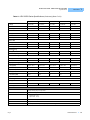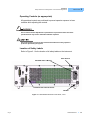
1
User’s Guide LDX-36000 Series High Power Laser Diode Current Source ILX Lightwave · 31950 Frontage Road · Bozeman, MT, U.S.A. 59715 · U.S. & Canada: 1-800-459-9459 · International Inquiries: 406-556-2481 · Fax 406-586-9405 ilx.custhelp.com · www.newport.com/ilxlightwave 70039705_01 September 2013 TA B L E O F C O N T E N T S TABLE OF CONTENTS Safety Information and the Manual . . . . . . . . . . . . . . . . . . . . . . . . . . . . . . . . . xi General Safety Considerations . . . . . . . . . . . . . . . . . . . . . . . . . . . . . . . . . . . . xi Safety Marking Symbols . . . . . . . . . . . . . . . . . . . . . . . . . . . . . . . . . . . . . . . . xiii Comments, Suggestions, and Problems . . . . . . . . . . . . . . . . . . . . . . . . . . . xv Chapter 1 Introduction and Specifications Product Overview . . . . . . . . . . . . . . . . . . . . . . . . . . . . . . . . . . . . . . . . . . . . . . . . 2 Installation . . . . . . . . . . . . . . . . . . . . . . . . . . . . . . . . . . . . . . . . . . . . . . . . . . . . . . 4 Initial Inspection . . . . . . . . . . . . . . . . . . . . . . . . . . . . . . . . . . . . . . . . . . . . . . . 4 Grounding Requirements . . . . . . . . . . . . . . . . . . . . . . . . . . . . . . . . . . . . . . . . 4 AC Power Requirements . . . . . . . . . . . . . . . . . . . . . . . . . . . . . . . . . . . . . . . . 4 GPIB Communications . . . . . . . . . . . . . . . . . . . . . . . . . . . . . . . . . . . . . . . . . . 4 Tilt-Foot Adjustment . . . . . . . . . . . . . . . . . . . . . . . . . . . . . . . . . . . . . . . . . . . . 5 Shipping Kit . . . . . . . . . . . . . . . . . . . . . . . . . . . . . . . . . . . . . . . . . . . . . . . . . . . 5 External Interlocks . . . . . . . . . . . . . . . . . . . . . . . . . . . . . . . . . . . . . . . . . . . . . 5 Obtaining Repair Services . . . . . . . . . . . . . . . . . . . . . . . . . . . . . . . . . . . . . . . 6 Options and Accessories . . . . . . . . . . . . . . . . . . . . . . . . . . . . . . . . . . . . . . . . 6 Specifications . . . . . . . . . . . . . . . . . . . . . . . . . . . . . . . . . . . . . . . . . . . . . . . . . . . 7 Chapter 2 Safety Electrical Safety . . . . . . . . . . . . . . . . . . . . . . . . . . . . . . . . . . . . . . . . . . . . . . . . . 17 Laser Safety . . . . . . . . . . . . . . . . . . . . . . . . . . . . . . . . . . . . . . . . . . . . . . . . . . . . 18 Optical Safety . . . . . . . . . . . . . . . . . . . . . . . . . . . . . . . . . . . . . . . . . . . . . . . . . . 18 03_10 LDX-36000 Series i TA B L E O F C O N T E N T S Safety Features and Compliance to Government Regulations . . . . . . . . . . . 20 Laser Classification (as appropriate) . . . . . . . . . . . . . . . . . . . . . . . . . . . . . . 20 Protective Housing (as appropriate) . . . . . . . . . . . . . . . . . . . . . . . . . . . . . . . 20 Laser Emission Indicators (as appropriate) . . . . . . . . . . . . . . . . . . . . . . . . . 20 Operating Controls (as appropriate) . . . . . . . . . . . . . . . . . . . . . . . . . . . . . . . 21 Location of Safety Labels . . . . . . . . . . . . . . . . . . . . . . . . . . . . . . . . . . . . . . . 21 Chapter 3 Operation Power-Up . . . . . . . . . . . . . . . . . . . . . . . . . . . . . . . . . . . . . . . . . . . . . . . . . . . . . . 23 Power-Up Sequence . . . . . . . . . . . . . . . . . . . . . . . . . . . . . . . . . . . . . . . . . . . 23 Power-On State . . . . . . . . . . . . . . . . . . . . . . . . . . . . . . . . . . . . . . . . . . . . . . 24 Connections for General Operation . . . . . . . . . . . . . . . . . . . . . . . . . . . . . . . . 24 Inductance . . . . . . . . . . . . . . . . . . . . . . . . . . . . . . . . . . . . . . . . . . . . . . . . . . 25 Laser Current Source Output . . . . . . . . . . . . . . . . . . . . . . . . . . . . . . . . . . . . 26 External Interlocks . . . . . . . . . . . . . . . . . . . . . . . . . . . . . . . . . . . . . . . . . . . . 28 Forward Voltage Measurement . . . . . . . . . . . . . . . . . . . . . . . . . . . . . . . . . . 28 External Photodiode Measurement . . . . . . . . . . . . . . . . . . . . . . . . . . . . . . . 29 Grounding Considerations . . . . . . . . . . . . . . . . . . . . . . . . . . . . . . . . . . . . . . 29 Temperature Measurement . . . . . . . . . . . . . . . . . . . . . . . . . . . . . . . . . . . . . 29 Front Panel Operation . . . . . . . . . . . . . . . . . . . . . . . . . . . . . . . . . . . . . . . . . . . . 30 The Adjust Knob . . . . . . . . . . . . . . . . . . . . . . . . . . . . . . . . . . . . . . . . . . . . . . 30 Display 1 . . . . . . . . . . . . . . . . . . . . . . . . . . . . . . . . . . . . . . . . . . . . . . . . . . . . 30 Display 2 . . . . . . . . . . . . . . . . . . . . . . . . . . . . . . . . . . . . . . . . . . . . . . . . . . . . 31 Temperature Measurement Setup . . . . . . . . . . . . . . . . . . . . . . . . . . . . . . . . 32 Limit Setup . . . . . . . . . . . . . . . . . . . . . . . . . . . . . . . . . . . . . . . . . . . . . . . . . . 34 Configuring the Operational Mode . . . . . . . . . . . . . . . . . . . . . . . . . . . . . . . . 35 Adjusting Current Setpoint . . . . . . . . . . . . . . . . . . . . . . . . . . . . . . . . . . . . . . 35 Enabling CW Output . . . . . . . . . . . . . . . . . . . . . . . . . . . . . . . . . . . . . . . . . . . 35 QCW (Pulsed) Mode Setup . . . . . . . . . . . . . . . . . . . . . . . . . . . . . . . . . . . . . QCW-Pulse Mode . . . . . . . . . . . . . . . . . . . . . . . . . . . . . . . . . . . . . . . . . . . QCW-Trig Mode . . . . . . . . . . . . . . . . . . . . . . . . . . . . . . . . . . . . . . . . . . . . . Hard Pulse Mode . . . . . . . . . . . . . . . . . . . . . . . . . . . . . . . . . . . . . . . . . . . . Automatic Shutoff Conditions for Current Output . . . . . . . . . . . . . . . . . . . 36 38 39 40 41 Additional Functions and Features . . . . . . . . . . . . . . . . . . . . . . . . . . . . . . . . 41 ii LDX-36000 Series TA B L E O F C O N T E N T S Adjusting Current Setpoint in Terms of Optical Power . . . . . . . . . . . . . . . Configuring External Photodiode Power Measurements . . . . . . . . . . . . . . Adjustable Photodiode Bias . . . . . . . . . . . . . . . . . . . . . . . . . . . . . . . . . . . . LIV Sweep Mode . . . . . . . . . . . . . . . . . . . . . . . . . . . . . . . . . . . . . . . . . . . . Pulse Out . . . . . . . . . . . . . . . . . . . . . . . . . . . . . . . . . . . . . . . . . . . . . . . . . . Trigger In . . . . . . . . . . . . . . . . . . . . . . . . . . . . . . . . . . . . . . . . . . . . . . . . . . Trigger Out . . . . . . . . . . . . . . . . . . . . . . . . . . . . . . . . . . . . . . . . . . . . . . . . . Saving and Recalling from the Front Panel . . . . . . . . . . . . . . . . . . . . . . . . Chapter 4 41 43 43 43 44 45 45 46 Remote Operation Basic GPIB Concepts . . . . . . . . . . . . . . . . . . . . . . . . . . . . . . . . . . . . . . . . . . . . 47 Data and Interface Messages . . . . . . . . . . . . . . . . . . . . . . . . . . . . . . . . . . . . 47 Talkers, Listeners, and Controllers . . . . . . . . . . . . . . . . . . . . . . . . . . . . . . . . 48 GPIB Cable Connections . . . . . . . . . . . . . . . . . . . . . . . . . . . . . . . . . . . . . . . 48 The GPIB Connector . . . . . . . . . . . . . . . . . . . . . . . . . . . . . . . . . . . . . . . . . . 48 Reading the GPIB Address . . . . . . . . . . . . . . . . . . . . . . . . . . . . . . . . . . . . . . 50 Changing the GPIB Address . . . . . . . . . . . . . . . . . . . . . . . . . . . . . . . . . . . . . 50 Changing Operation from Local to Remote . . . . . . . . . . . . . . . . . . . . . . . . . 50 Command Syntax . . . . . . . . . . . . . . . . . . . . . . . . . . . . . . . . . . . . . . . . . . . . . . . 51 Letters . . . . . . . . . . . . . . . . . . . . . . . . . . . . . . . . . . . . . . . . . . . . . . . . . . . . . . 51 White Space . . . . . . . . . . . . . . . . . . . . . . . . . . . . . . . . . . . . . . . . . . . . . . . . . 51 Terminators . . . . . . . . . . . . . . . . . . . . . . . . . . . . . . . . . . . . . . . . . . . . . . . . . . 52 Command Separators . . . . . . . . . . . . . . . . . . . . . . . . . . . . . . . . . . . . . . . . . . 52 Parameters . . . . . . . . . . . . . . . . . . . . . . . . . . . . . . . . . . . . . . . . . . . . . . . . . . 52 Command Tree Structure . . . . . . . . . . . . . . . . . . . . . . . . . . . . . . . . . . . . . . . 54 Syntax Summary . . . . . . . . . . . . . . . . . . . . . . . . . . . . . . . . . . . . . . . . . . . . . 55 IEEE-488.2 Command Commands . . . . . . . . . . . . . . . . . . . . . . . . . . . . . . . . . . 56 LDX-36000 Commonly Used Commands . . . . . . . . . . . . . . . . . . . . . . . . . . . . 58 Status Reporting . . . . . . . . . . . . . . . . . . . . . . . . . . . . . . . . . . . . . . . . . . . . . . . . 60 Event Condition Registers . . . . . . . . . . . . . . . . . . . . . . . . . . . . . . . . . . . . . . 60 Operation Complete Definition . . . . . . . . . . . . . . . . . . . . . . . . . . . . . . . . . . 61 Output Off Register . . . . . . . . . . . . . . . . . . . . . . . . . . . . . . . . . . . . . . . . . . . . 62 Command Timing . . . . . . . . . . . . . . . . . . . . . . . . . . . . . . . . . . . . . . . . . . . . . . . 63 Sequential / Overlapped Commands . . . . . . . . . . . . . . . . . . . . . . . . . . . . . . 63 Query Response Timing . . . . . . . . . . . . . . . . . . . . . . . . . . . . . . . . . . . . . . . . 63 03_10 LDX-36000 Series iii TA B L E O F C O N T E N T S Chapter 5 Command Reference Remote Command Reference Summary . . . . . . . . . . . . . . . . . . . . . . . . . . . . . 66 Command Reference . . . . . . . . . . . . . . . . . . . . . . . . . . . . . . . . . . . . . . . . . . . . 71 Chapter 6 Calibration and Troubleshooting Calibration Overview . . . . . . . . . . . . . . . . . . . . . . . . . . . . . . . . . . . . . . . . . . . . 124 Beginning Calibration . . . . . . . . . . . . . . . . . . . . . . . . . . . . . . . . . . . . . . . . . 125 Laser Diode Current Setpoint Calibration . . . . . . . . . . . . . . . . . . . . . . . . . . . 126 QCW Calibration . . . . . . . . . . . . . . . . . . . . . . . . . . . . . . . . . . . . . . . . . . . . . . . 127 Laser Diode Voltage Measurement Calibration . . . . . . . . . . . . . . . . . . . . . . 128 Voltage Limit Setpoint . . . . . . . . . . . . . . . . . . . . . . . . . . . . . . . . . . . . . . . . . . . 129 Photodiode Current (PDI) Measurement . . . . . . . . . . . . . . . . . . . . . . . . . . . . 130 Thermistor Calibration . . . . . . . . . . . . . . . . . . . . . . . . . . . . . . . . . . . . . . . . . . 131 Troubleshooting . . . . . . . . . . . . . . . . . . . . . . . . . . . . . . . . . . . . . . . . . . . . . . . 133 Error Messages . . . . . . . . . . . . . . . . . . . . . . . . . . . . . . . . . . . . . . . . . . . . . . . . 135 E-503 Error . . . . . . . . . . . . . . . . . . . . . . . . . . . . . . . . . . . . . . . . . . . . . . . . . 137 E-599 Error . . . . . . . . . . . . . . . . . . . . . . . . . . . . . . . . . . . . . . . . . . . . . . . . . 137 Appendix A Allowed QCW Space Allowed QCW Operating Region . . . . . . . . . . . . . . . . . . . . . . . . . . . . . . . . . . 140 Appendix B Allowed QCW Space - LDX-36125-24 Allowed QCW Operating Region for 36125-24 . . . . . . . . . . . . . . . . . . . . . . . 142 iv LDX-36000 Series LIST OF FIGURES LIST OF FIGURES Figure 1.1 LDX-36000 Series Front Panel . . . . . . . . . . . . . . . . . . . . . 3 Figure 1.2 LDX-36000 Series Rear Panel, <50 A . . . . . . . . . . . . . . . . 3 Figure 1.3 LDX-36000 Series Rear Panel, >50 A . . . . . . . . . . . . . . . . 3 Figure 2.1 LDX-36000 Series Rear Panel Labels, <50 A . . . . . . . . . 21 Figure 2.2 LDX-36000 Series Rear Panel Labels, >50 A . . . . . . . . . 22 Figure 3.1 Laser and Photodiode Connections . . . . . . . . . . . . . . . . 26 Figure 3.2 LDX-36000 Output and Measurement Connector Pin Assignments, <50A . . . . . . . . . . . . . . . . . . . . . . . . . . . . . 27 Figure 3.3 LDX-36000 Output and Measurement Connector Pin Assignments, >50A . . . . . . . . . . . . . . . . . . . . . . . . . . . . . 27 Figure 3.4 External Interlocks . . . . . . . . . . . . . . . . . . . . . . . . . . . . . . 28 Figure 3.5 Adjust Knob . . . . . . . . . . . . . . . . . . . . . . . . . . . . . . . . . . . 30 Figure 3.6 Display 1 . . . . . . . . . . . . . . . . . . . . . . . . . . . . . . . . . . . . . 30 Figure 3.7 Display 2 . . . . . . . . . . . . . . . . . . . . . . . . . . . . . . . . . . . . . 31 Figure 3.8 Selecting Parameters . . . . . . . . . . . . . . . . . . . . . . . . . . . 34 Figure 3.9 Mode Selection . . . . . . . . . . . . . . . . . . . . . . . . . . . . . . . . 35 Figure 3.10 CW Mode Box . . . . . . . . . . . . . . . . . . . . . . . . . . . . . . . . 35 Figure 3.11 QCW Current Ramp Enabling Output . . . . . . . . . . . . . . 37 Figure 3.12 QCW Current Ramp with Output Enabled . . . . . . . . . . . 37 Figure 3.13 QCW Mode Box . . . . . . . . . . . . . . . . . . . . . . . . . . . . . . 38 Figure 3.14 QCW Timing Diagram . . . . . . . . . . . . . . . . . . . . . . . . . . 40 Figure 3.15 Determining Output Current Setpoint . . . . . . . . . . . . . . 42 03_10 LDX-36000 Series v LIST OF FIGURES Figure 4.1 GPIB Cable Connections . . . . . . . . . . . . . . . . . . . . . . . . 48 Figure 4.2 GPIB Connector Diagram . . . . . . . . . . . . . . . . . . . . . . . . 49 Figure 4.3 GPIB Local Button . . . . . . . . . . . . . . . . . . . . . . . . . . . . . . 50 Figure 4.4 Command Path Structure . . . . . . . . . . . . . . . . . . . . . . . . 54 Figure 4.5 Common Command Diagrams . . . . . . . . . . . . . . . . . . . . 56 Figure 4.6 Status Reporting Scheme . . . . . . . . . . . . . . . . . . . . . . . . 61 Figure 4.7 Laser Output Off Register . . . . . . . . . . . . . . . . . . . . . . . . 62 Figure A.1 Allowed QCW Operating Region . . . . . . . . . . . . . . . . . 140 Figure B.1 Allowed QCW Operating Region for LDX-36125-24 . . . 142 vi LDX-36000 Series L I S T O F TA B L E S LIST OF TABLES Table 1.1 Options and Accessories . . . . . . . . . . . . . . . . . . . . . . . . . . . 6 Table 1.2 LDX-36000 Series Specifications. . . . . . . . . . . . . . . . . . . . . 7 Table 3.1 LDX-36000 Series Default Configuration . . . . . . . . . . . . . . 24 Table 3.2 Display Indicators . . . . . . . . . . . . . . . . . . . . . . . . . . . . . . . . 32 Table 3.3 Typical 10 kW @ 25°C Thermistor Calibration Values. . . . 33 Table 3.4 Configuring QCW Parameters . . . . . . . . . . . . . . . . . . . . . . 36 Table 3.5 Automated L-I-V Mode GPIB Commands . . . . . . . . . . . . . 44 Table 4.1 Acceptable Spelling . . . . . . . . . . . . . . . . . . . . . . . . . . . . . . 51 Table 4.2 White Space . . . . . . . . . . . . . . . . . . . . . . . . . . . . . . . . . . . . 51 Table 4.3 Query Formatting . . . . . . . . . . . . . . . . . . . . . . . . . . . . . . . . 52 Table 4.4 Parameters. . . . . . . . . . . . . . . . . . . . . . . . . . . . . . . . . . . . . 53 Table 4.5 Substitute Parameter Values . . . . . . . . . . . . . . . . . . . . . . . 53 Table 4.6 Invalid Syntax Command Strings . . . . . . . . . . . . . . . . . . . . 55 Table 4.7 LDX-36000 IEEE Common Commands . . . . . . . . . . . . . . . 57 Table 4.8 LDX-36000 Commonly Used Commands . . . . . . . . . . . . . 58 Table 4.9 Default Output Off Register Settings . . . . . . . . . . . . . . . . . 62 Table 5.1 Remote Command Summary Reference List. . . . . . . . . . . 66 Table 6.1 Symptoms and Corrective Actions . . . . . . . . . . . . . . . . . . 133 Table 6.2 Error Code Classifications . . . . . . . . . . . . . . . . . . . . . . . . 135 Table 6.3 Error Messages . . . . . . . . . . . . . . . . . . . . . . . . . . . . . . . . 136 03_10 LDX-36000 Series vii L I S T O F TA B L E S viii LDX-36000 Series SAFETY AND WARRANTY INFORMATION The Safety and Warranty Information section provides details about cautionary symbols used in the manual, safety markings used on the instrument, and information about the Warranty including Customer Service contact information. Safety Information and the Manual Throughout this manual, you will see the words Caution and Warning indicating potentially dangerous or hazardous situations which, if not avoided, could result in death, serious or minor injury, or damage to the product. Caution indicates a potentially hazardous situation which can result in minor or moderate injury or damage to the product or equipment. Warning indicates a potentially dangerous situation which can result in serious injury or death. WARNING Visible and/or invisible laser radiation. Avoid eye or skin exposure to direct or scattered radiation. General Safety Considerations If any of the following conditions exist, or are suspected, do not use the instrument until safe operation can be verified by trained service personnel: • Visible damage • Severe transport stress • Prolonged storage under adverse conditions • Failure to perform intended measurements or functions If necessary, return the instrument to ILX Lightwave, or the authorized local ILX Lightwave distributor, for service or repair to ensure that safety features are maintained (see the contact information on page xiv). All instruments returned to ILX Lightwave are required to have a Return Authorization Number assigned by an official representative of ILX Lightwave Corporation. See Returning an Instrument on page xii for more information. LDX-36000 Series ix SAFETY SYMBOLS SAFETY SYMBOLS This section describes the safety symbols and classifications. Technical specifications including electrical ratings and weight are included within the manual. See the Table of Contents to locate the specifications and other product information. The following classifications are standard across all ILX Lightwave products: x • Indoor use only • Ordinary Protection: This product is NOT protected against the harmful ingress of moisture. • Class I Equipment (grounded type) • Mains supply voltage fluctuations are not to exceed ±10% of the nominal supply voltage. • Pollution Degree 2 • Installation (overvoltage) Category II for transient overvoltages • Maximum Relative Humidity: <80% RH, non-condensing • Operating temperature range of 0 °C to 40 °C • Storage and transportation temperature of –40 °C to 70 °C • Maximum altitude: 3000 m (9843 ft.) • This equipment is suitable for continuous operation. LDX-36000 Series Safety Marking Symbols This section provides a description of the safety marking symbols that appear on the instrument. These symbols provide information about potentially dangerous situations which can result in death, injury, or damage to the instrument and other components. Caution, refer to manual Earth ground Terminal Alternating current Visible and/or invisible laser radiation Caution, risk of electric shock Protective Conductor Terminal Caution, hot surface Frame or chassis Terminal On: In position of a bistable push control. The slash (I) only denotes that mains are on. or (I) Off: Out position of a bistable push control. The circle (O) only denotes that mains are off. or (O) Standby: This switch does not fully disconnect the instrument from the power supply. 03_10 LDX-36000 Series xi WA R R A N T Y WARRANTY ILX LIGHTWAVE CORPORATION warrants this instrument to be free from defects in material and workmanship for a period of one year from date of shipment. During the warranty period, ILX will repair or replace the unit, at our option, without charge. Limitations This warranty does not apply to fuses, lamps, defects caused by abuse, modifications, or to use of the product for which it was not intended. This warranty is in lieu of all other warranties, expressed or implied, including any implied warranty of merchantability or fitness for any particular purpose. ILX Lightwave Corporation shall not be liable for any incidental, special, or consequential damages. If a problem occurs, please contact ILX Lightwave Corporation with the instrument's serial number, and thoroughly describe the nature of the problem. Returning an Instrument If an instrument is to be shipped to ILX Lightwave for repair or service, be sure to: 1 Obtain a Return Authorization number (RA) from ILX Customer Service. 2 Attach a tag to the instrument identifying the owner and indicating the required service or repair. Include the instrument serial number from the rear panel of the instrument. 3 Attach the anti-static protective caps that were shipped with the instrument and place the instrument in a protective anti-static bag. 4 Place the instrument in the original packing container with at least 3 inches (7.5 cm) of compressible packaging material. Shipping damage is not covered by this warranty. 5 Secure the packing box with fiber reinforced strapping tape or metal bands. 6 Send the instrument, transportation pre-paid, to ILX Lightwave. Clearly write the return authorization number on the outside of the box and on the shipping paperwork. ILX Lightwave recommends you insure the shipment. If the original shipping container is not available, place the instrument in a container with at least 3 inches (7.5 cm) of compressible packaging material on all sides. Repairs are made and the instrument returned transportation pre-paid. Repairs are warranted for the remainder of the original warranty or for 90 days, whichever is greater. xii LDX-36000 Series WA R R A N T Y Claims for Shipping Damage When you receive the instrument, inspect it immediately for any damage or shortages on the packing list. If the instrument is damaged, file a claim with the carrier. The factory will supply you with a quotation for estimated costs of repair. You must negotiate and settle with the carrier for the amount of damage. Comments, Suggestions, and Problems To ensure that you get the most out of your ILX Lightwave product, we ask that you direct any product operation or service related questions or comments to ILX Lightwave Customer Support. You may contact us in whatever way is most convenient. In the United States: Phone . . . . . . . . . . . . . . . . . . . . . . . . . . . (800) 459-9459 or (406) 586-1244 Fax . . . . . . . . . . . . . . . . . . . . . . . . . . . . . . . . . . . . . . . . . . . . . (406) 586-9405 Online: . . . . . . . . . . . . . . . . . . . . . . . . . . . . . . . . . . . . . http://ilx.custhelp.com Email: . . . . . . . . . . . . . . . . . . . . . . . . . . . . . . . . . . . [email protected] Or mail to: ILX Lightwave Corporation P. O. Box 6310 Bozeman, Montana, U.S.A 59771 www.ilxlightwave.com In Europe: Optical Test and Calibration Ltd. Listerhills Science Park Bradford, BD7 1HR United Kingdom Phone: (44) 1274 393857 Fax: (44) 1274 393336 Online: www.otc.co.uk Email: [email protected] In China: ETSC Technologies Co. 9/F Building 1 SBI Street Dongxin Road East Lake High-Tech Development Zone Wuhan, Hubei, 430074 PRC China Phone: (86) 27 8717 0152; (86) 27 8741 2681; (86) 27 8780 7925 Fax: (86) 27 8780 7133 Online: www.etsc-tech.com Email: [email protected] 03_10 In Japan: Kyosai Technos 424, Shimo-Ongata-Machi Hachioji-Shi Tokyo, 192-0154 Japan Phone: (81) 426 521 388 Fax: (81) 426 513 270 In China: Kyosai Technos 3F Bldg G, No.21 Changjiang Road, Wuxi National Hi-Tech Development Zone Jiangsu, P.R. China Phone: (86) 510 522 1707 Fax: (86) 510 522 1679 Email: [email protected] LDX-36000 Series xiii WA R R A N T Y When you contact us, please have the following information: Model Number: Serial Number: End-user Name: Company: Phone: Fax: Description of what is connected to the ILX Lightwave instrument: Description of the problem: If ILX Lightwave determines that a return to the factory is necessary, you are issued a Return Authorization (RA) number. Please mark this number on the outside of the shipping box. You or your shipping service are responsible for any shipping damage when returning the instrument to ILX Lightwave; ILX recommends you insure the shipment. If the original shipping container is not available, place your instrument in a container with at least 3 inches (7.5 cm) of compressible packaging material on all sides. We look forward to serving you even better in the future! xiv LDX-36000 Series CHAPTER 1 INTRODUCTION AND SPECIFICATIONS This chapter is an introduction to the LDX-36000 Series High Power Laser Diode Current Sources. The chapter contains first time setup information, important safety considerations, maintenance information, instrument specifications, and general LDX-36000 Series information. If any of the following symptoms exist, or are even suspected, remove the LDX-36000 from service. Do not use the instrument until trained service personnel can verify safe operation. • Visible damage • Severe transport stress • Prolonged storage under adverse conditions • Failure to perform intended measurements of functions If necessary, call ILX Lightwave Customer Service to ensure that all safety features are maintained and functioning correctly. LDX-36000 Series 1 CHAPTER 1 INTRODUCTION AND SPECIFICATIONS Product Overview Product Overview The LDX-36000 Series High Power Laser Diode Current Sources are capable of delivering very high currents, up to 125A CW and 220A QCW with a compliance voltage up to 35 Volts. These current sources are designed for testing and controlling multiple high power laser diodes with specially designed features such as high set-point accuracy, low output noise, forward voltage and photodiode measurement and an adjustable photodiode reverse bias voltage. These current sources also offer many laser diode protection features which protect the laser diode during testing from electrical transients and providing safeguards such as adjustable voltage and current limits. Low current overshoot in either CW or QCW mode and closed loop power supply control prevent surge currents in the case of a device failure with multiple diodes connected in series. A thermistor based temperature monitor provides additional protection through a programmable temperature limit which can be used to disable the laser output when a temperature limit is exceeded. Dual independent interlocks are provided for further laser and operator protection. Remote instrument operation is possible on all LDX-36000 Series Current Sources through an IEEE488/GPIB interface. All instrument controls and functions are programmable for test sequencing, measurements and data handling in automated test systems. Synchronization with other measurement or control instruments is possible with an input and output trigger function with programmable delays. Multiple test configurations can be saved and easily recalled through Save and Recall functions from the front panel or through the GPIB interface. 2 LDX-36000 Series INTRODUCTION AND SPECIFICATIONS Product Overview CHAPTER 1 Figure 1.1 LDX-36000 Series Front Panel Figure 1.2 LDX-36000 Series Rear Panel, <50 A Figure 1.3 LDX-36000 Series Rear Panel, >50 A 03_10 LDX-36000 Series 3 CHAPTER 1 INTRODUCTION AND SPECIFICATIONS Installation Installation Initial Inspection After receiving the LDX-36000 Series Current Source, verify that the following items were shipped along with the instrument: • LDX-36000 Series User’s Guide • Power Cord Appropriate for the Local Service • Shipping Kit Grounding Requirements The LDX-36000 Current Source comes with a three-conductor AC power cable. The power cable must be inserted into an approved three-contact electrical outlet or used with a three-contact to two-contact adapter with the grounding wire connected to an electrical ground (safety ground). The AC input and supplied power cable meets IEC safety standards. AC Power Requirements The LDX-36000 Series Current Sources may be operated from a single phase power source delivering nominal line voltages in the range of 100 to 240 VAC ±10% (all values RMS), from 50 to 60 Hz. Please refer to specifications for proper line voltage for your instrument. The internal power supplies are autoranging so no reconfiguration is necessary to operate at different input voltages. Maximum power consumption depends on the model. Before connecting the LDX-36000 Current Source to a power source, verify that the AC power source is within the voltage range printed on the instrument's rear panel. To avoid electrical shock hazard, connect the instrument to properly earth-grounded electrical receptacles only. Failure to observe this precaution may result in severe injury or death. GPIB Communications The IEEE-488 GPIB interface connector is located on the rear panel in the upper left-hand side of the panel as shown in Figure 1.2. Attach a GPIB cable to the 24pin connector. The connectors are polarized to ensure proper orientation. Fingertighten the two jack screws on either side of the connector to prevent the cable from inadvertently becoming disconnected. 4 LDX-36000 Series INTRODUCTION AND SPECIFICATIONS Installation CHAPTER 1 A total of 15 devices may be connected together on the same GPIB interface bus. The cables have single male/female connectors on each end so that the cables can be stacked. This allows multiple cables to be attached to a single instrument. However, the maximum cable length must not exceed 20 meters (65 feet) total, or 2 meters (6.5 feet) per device. The talk and listen addresses of the instrument are identical. This GPIB address is read by pressing the GPIB/LOCAL button with the address shown on the lefthand display. The instrument comes from the factory with the GPIB address set to 1. This may be changed from the front panel and is described in the section entitled Changing the GPIB Address in Chapter 4. For additional information, refer to Chapter 4 - Remote Operation. Tilt-Foot Adjustment The LDX-36000 Series Current Sources come standard with folding front legs and two rear feet to use as a benchtop instrument. Extending the front feet so the instrument front panel is tilted up makes it easier to view the displays. To use them, place the unit on a stable base and rotate the front legs downward until they lock into position. Shipping Kit The LDX-36000 Series Current Sources come with a shipping kit containing accessories the user will find useful in getting the instrument operational. These accessories include screws and clip nuts for rack mounting and a DB-9 connector and hood to mate with the 9-pin measurement connector on the instrument’s rear panel. Also included are connectors for mating to the high current output connectors. For current sources of <50 A, a DB-25 pin connector, pins and hood are included in the shipping kit. For current sources of >50A, high current output lugs and screws are provided to attach to the output pads on the rear panel. For QCW operation with the ILX CC-390 output cable, a high current crown connector is also included in the high current shipping kit. External Interlocks The instrument's rear panel contains two pairs of terminal blocks which are used for connecting to two independently monitored interlock circuits. The terminals of each terminal block must be shorted to satisfy each interlock. As an example of their use, one interlock could be connected to the flowswitch in a liquid cooling unit while the other could be tied to a door sensor. However, both are simply labeled as Interlock 1 and Interlock 2 to allow complete flexibility for the user. 03_10 LDX-36000 Series 5 CHAPTER INTRODUCTION AND SPECIFICATIONS Installation 1 Obtaining Repair Services The instrument may at some point need to be returned to the factory for service whether or not it is under warranty. If the warranty has expired, there will be a nominal charge for repair and/or calibration. See the section entitled Returning an Instrument in the Preface for shipping and contact information. Potentially lethal voltages exist within the LDX-36000 chassis even with the key switch in the off position. To avoid electric shock, do not perform any maintenance on the instrument. Qualified service personnel trained in ESD prevention are required. High voltages are present on and around the printed circuit boards. To disconnect the AC mains supply, remove the power cord from the instrument. If the AC mains outlet is not easily accessible after instrument installation, ensure that an external disconnect switch is provided to remove AC power to the instrument. There are no user-serviceable parts inside the instrument, excepting any external fuses in the AC power entry module. Contact ILX Customer Service for information about servicing the instrument. Options and Accessories Options and accessories for the LDX-36000 series of instruments include the following: Table 1.1 Options and Accessories Description Model Number 125 Amp Output Cable, D-sub CC-340 50 Amp Output Cable, 6 feet CC-370 125 Amp Output Cable, 6 feet CC-390 125 Amp Output Cable, 12 feet CC-395 Calibrated 10 k Thermistor TS-510 Uncalibrated 10 k Thermistor TS-520 Our goal is to make the best laser diode instrumentation available anywhere. To achieve this, we need your ideas and comments on ways we can improve our products. We invite you to contact us at any time with your suggestions. 6 LDX-36000 Series INTRODUCTION AND SPECIFICATIONS Specifications CHAPTER 1 Specifications Table 1.2 LDX-36000 Series Specifications (Sheet 1 of 8) 36010-12 DRIVE CURRENT OUTPUT 36025-12 36050-12 36085-12 36125-12 1 Output Current Range CW 10A 25A 50A 85A 125A Pulse 20A 50A 100A 170A 220A HPulse 10A 25A 50A 85A 125A 10 mA 10 mA 10 mA 10 mA 10 mA +(0.1%+10mA) +(0.1%+10mA) +(0.1%+20mA) +(0.1%+80mA) +(0.1%+120mA) CW3 20 s 20 s 20 s 20 s 20 s Pulse4 80 s 80 s 80 s 80 s 80 s HPulse4 550 s 550 s 550 s 550 s 550 s Maximum CW Power 120W 300W 600W 1020W 1500W Compliance Voltage5 12V 12V 12V 12V 12V Setpoint Resolution Setpoint Accuracy2 Settling Time ppm/oC +50 ppm/oC +50 ppm/oC +50 ppm/oC +50 ppm/oC Temperature Coefficient +50 Stability6 +100 ppm +100 ppm +100 ppm +100 ppm +100 ppm <5 mA rms <10 mA rms <20 mA rms <40 mA rms <60 mA rms <40 mA <40 mA <40 mA <40 mA <40 mA <80 mA <80 mA <100 mA <320 mA <320 mA Pulse Mode Range 40s to 1ms 40s to 1ms 40s to 1ms 40s to 1ms 40s to 1ms HPulse Mode Range 1ms to 2 s 1ms to 2 s 1ms to 2 s 1ms to 2 s 1ms to 2 s Pulse Mode 2 s 2 s 2 s 2 s 2 s HPulse Mode .01% +0.5 s .01% +0.5 s .01% +0.5 s .01% +0.5 s .01% +0.5 s Pulse Mode + 10 s + 10 s + 10 s + 10 s + 10 s HPulse Mode10 + 20 s + 20 s + 20 s + 20 s + 20 s Range 0.1 to 1000 Hz 0.1 to 1000 Hz 0.1 to 1000 Hz 0.1 to 1000 Hz 0.1 to 1000 Hz Resolution 0.1 Hz 0.1 Hz 0.1 Hz 0.1 Hz 0.1 Hz Accuracy11 + 0.1% + 0.1% + 0.1% + 0.1% + 0.1% Noise and Ripple7 Transients Operational8 1 kV EFT / QCW Surge9 MODE10, 25 Pulse Width Resolution Accuracy Pulse Frequency 03_10 LDX-36000 Series 7 CHAPTER INTRODUCTION AND SPECIFICATIONS Specifications 1 Table 1.2 LDX-36000 Series Specifications (Continued) (Sheet 2 of 8) 36010-12 36025-12 36050-12 36085-12 36125-12 Duty Cycle Pulse Mode 0.5 to 20% 0.5 to 20% 0.5 to 20% 0.5 to 20% 0.5 to 10% HPulse Mode 20 to 90% 20 to 90% 20 to 90% 20 to 90% 10 to 90% Resolution 0.1% 0.1% 0.1% 0.1% 0.1% Rise / Fall Time 12 Pulse Mode <10 s <10 s <20 s <20 s <20 s HPulse Mode 200 s 200 s 200 s 200 s 200 s <2% <2% <2% <2% <2% Range 0 - 14.0 V 0 − 14.0 V 0 − 14.0 V 0 − 14.0 V 0 − 14.0 V Resolution 100 mV 100 mV 100 mV 100 mV 100 mV +1%+200mV +1%+200mV +1%+200mV +1%+200mV +1%+200mV Range CW 0 to 10.5A 0 to 26.2A 0 to 52.5A 0 to 89.2A 0 to 131.2A Range QCW 0 to 22.0A 0 to 53.5A 0 to 106.0A 0 to 179.5A 0 to 232.0A Range HPulse 0 to 10.5A 0 to 26.2A 0 to 52.5A 0 to 89.2A 0 to 131.2A Overshoot13 VOLTAGE LIMIT Accuracy 14 11 CURRENT LIMIT Resolution Firmware Limit Accuracy 15 Hardware Limit Accuracy15 10 mA 10 mA 100 mA 10 mA 10 mA +0.1%+10mA +0.1%+10mA +0.1%+20mA +0.1%+80mA +0.1%+120mA +1%+10mA +1%+10mA +1%+20mA +1%+80mA +1%+120mA EVENT TRIGGERING (ALL MODELS) Trigger Output16 TTL Level; active high Pulse Width 10 s Delay Programmable Accuracy 2 s + 0.05% Range 0 s to 1s Resolution 0.01% + 5 s Jitter 100 ns Trigger Input 17 Delay to Output Programmable Accuracy 2 s + 0.05% Range 20 s to 1s Resolution 0.01% + 5 s Jitter 200 ns Pulse Trigger Output 8 TTL Level; rising edge triggered, single shot to 1 KHz; high impedance LDX-36000 Series TTL Level, high impedance, active high INTRODUCTION AND SPECIFICATIONS Specifications CHAPTER 1 Table 1.2 LDX-36000 Series Specifications (Continued) (Sheet 3 of 8) 36010-12 36025-12 36050-12 36085-12 36125-12 MEASUREMENT Forward Voltage Range 0 to 12.00V 0 to 12.00V 0 to 12.00V 0 to 12.00V 0 to 12.00V 10 mV 10 mV 10 mV 10 mV 10 mV +0.05% +20mV +0.05% +20mV +0.05% +20mV +0.05% +20mV +0.05% +20mV 3 to 10000A 3 to 10000A 3 to 10000A 3 to 10000A 3 to 10000A 3 A 3 A 3 A 3 A 3 A +0.1% +0.1% +0.1% +0.1% +0.1% Range 0 to -15 V 0 to -15 V 0 to -15 V 0 to -15 V 0 to -15 V Resolution 100 mV 100 mV 100 mV 100 mV 100 mV Accuracy +2.5% FS +2.5% FS +2.5% FS +2.5% FS +2.5% FS Range20 (mA/W) 0.001 to 100.00 0.001 to 100.00 0.001 to 100.00 0.001 to 100.00 0.001 to 100.00 Resolution (mA/W) .001 .001 .001 .001 .001 Range 0 to 1000W 0 to 1000W 0 to 1000W 0 to 1000W 0 to 1000W Resolution 1W 1W 1W 1W 1W Range (W/A) 0.00 to 10.00 0.00 to 10.00 0.00 to 10.00 0.00 to 10.00 0.00 to 10.00 Resolution (W/A) 0.01 0.01 0.01 0.01 0.01 Range (W/A) 0.00 to 10.00 0.00 to 25.00 0.00 to 50.00 0.00 to 85.00 0.00 to 125.00 Resolution (W/A) 0.01 0.01 0.1 0.1 0.1 100 A 100 A 100 A 100 A Resolution Accuracy 18 Photodiode Current Range Resolution Accuracy 19 Reverse Bias PD Responsivity Power Control Range P1 (Slope Efficiency) P2 (Threshold) Temperature Sensor Type 10K Thermistor Range 0 to +199.9 oC Thermistor Current 100 A Accuracy21 +0.2 oC LASER DIODE PROTECTION Output shorting relay, normally closed 2s turn-on delay (per 21CFR 1040.10) Hardware Fault Response Time24 Current Limit: <2 s Open Circuit: <50 s Intermittent contact protection 03_10 LDX-36000 Series 9 CHAPTER 1 INTRODUCTION AND SPECIFICATIONS Specifications Table 1.2 LDX-36000 Series Specifications (Continued) (Sheet 4 of 8) 36010-12 36025-12 36050-12 36085-12 36125-12 AC power failure / brown-out detection; error monitoring and reporting Transient protection: output on/off, power up/down, EFT/surge, 1000V Adjustable current and voltage limit; redundant hardware current and voltage limit INTERLOCKS Interlock 1 Normally open, close to enable output Interlock 2 Normally open, close to enable output Fault Response Time22 <6 ms GENERAL GPIB Interface IEEE/488 On-Board Memory Storage 1000 points On-Board Upload Rate 30 ms/point Power Requirements 100/240 VAC + 10% 100/240 VAC + 10% Maximum Current Draw 4A/2A Size (H x W x D)23 146mm x 483mm x 451mm (5.25” x 19” x 17.75”) Weight 10.9 kg/24 lbs Operating Temperature 0 oC 6A/3A 100/240 VAC + 10% to 40 oC 11.9 kg/26 lbs 10A/5A 11.9 kg/26 lbs 220/240 VAC + 10% 15A/7.5A 20A/10A 13.5 kg/30 lbs 15.2 kg/34 lbs Bus Bar Bus Bar oC to 70 oC Storage Temperature -40 Humidity 20 - 85% non-condensing Safety EN60950 Low Voltage Directive; 21CFR 1040.10 Regulatory Compliance CE Certified CE 220/240 VAC + 10% EN61326-1: 2006 Basic Requirements; Immunity EN55011:1007 Radiated and Conducted Emissions EN61010-1: Safety Requirements Connectors Current Output Hybrid D-sub Measurement DB 9 rear panel Interlocks Terminal block Pulse Trigger Out BNC rear panel Input/Output Trigger BNC front panel 10 LDX-36000 Series Hybrid D-sub Hybrid D-sub INTRODUCTION AND SPECIFICATIONS Specifications CHAPTER 1 Table 1.2 LDX-36000 Series Specifications (Continued) (Sheet 5 of 8) 36010-35 DRIVE CURRENT OUTPUT 36018-35 36040-30 36070-30 36125-24 1 Output Current Range CW 10A 18A 40A 70A 125A Pulse 20A 40A 80A 160A 220A HPulse 10A 18A 40A 70A 125A 10 mA 10 mA 10 mA 10 mA 10 mA +(0.1%+10mA) +(0.1%+10mA) +(0.1%+20mA) +(0.1%+80mA) +(0.1%+120mA) CW3 20 s 20 s 20 s 20 s 20 s Pulse4 80 s 80 s 80 s 80 s 80 s HPulse4 550 s 550 s 550 s 550 s 550 s Maximum CW Power 350W 630W 1200W 2380W 3000W Compliance Voltage5 35V 35V 30V 30V 24V Setpoint Resolution Setpoint Accuracy2 Settling Time ppm/oC +50 ppm/oC +50 ppm/oC +50 ppm/oC +50 ppm/oC Temperature Coefficient +50 Stability6 +100 ppm +100 ppm +100 ppm +100 ppm +100 ppm <10 mA rms <10 mA rms <10 mA rms <40 mA rms <60 mA rms <40 mA <40 mA <40 mA <40 mA <40 mA <80 mA <80 mA <100 mA <320 mA <320 mA Pulse Mode Range 40s to 1ms 40s to 1ms 40s to 1ms 40s to 1ms 40s to 1ms HPulse Mode Range 1ms to 2 s 1ms to 2 s 1ms to 2 s 1ms to 2 s 1ms to 2 s Pulse Mode 2 s 2 s 2 s 2 s 2 s HPulse Mode .01% +0.5 s .01% +0.5 s .01% +0.5 s .01% +0.5 s .01% +0.5 s Pulse Mode + 10 s + 10 s + 10 s + 10 s + 10 s HPulse Mode10 + 20 s + 20 s + 20 s + 20 s + 20 s Range 0.1 to 1000 Hz 0.1 to 1000 Hz 0.1 to 1000 Hz 0.1 to 1000 Hz 0.1 to 1000 Hz Resolution 0.1 Hz 0.1 Hz 0.1 Hz 0.1 Hz 0.1 Hz Accuracy11 + 0.1% + 0.1% + 0.1% + 0.1% + 0.1% Noise and Ripple7 Transients Operational8 1 kV EFT / QCW Surge9 MODE10, 25 Pulse Width Resolution Accuracy Pulse Frequency 03_10 LDX-36000 Series 11 CHAPTER INTRODUCTION AND SPECIFICATIONS Specifications 1 Table 1.2 LDX-36000 Series Specifications (Continued) (Sheet 6 of 8) 36010-35 36018-35 36040-30 36070-30 36125-24 Duty Cycle Pulse Mode 0.5 to 20% 0.5 to 20% 0.5 to 20% 0.5 to 20% 0.5 to 10% HPulse Mode 20 to 90% 20 to 90% 20 to 90% 20 to 90% 10 to 90% Resolution 0.1% 0.1% 0.1% 0.1% 0.1% Rise / Fall Time 12 Pulse Mode <10 s <10 s <20 s <20 s <20 s HPulse Mode 200 s 200 s 200 s 200 s 200 s <2% <2% <2% <2% <2% Range 0 - 38 V 0 − 38 V 0 − 33 V 0 − 33 V 0 − 27 V Resolution 100 mV 100 mV 100 mV 100 mV 100 mV +1%+200mV +1%+200mV +1%+200mV +1%+200mV +1%+200mV Range CW 0 to 10.5A 0 to 18.9A 0 to 42.0A 0 to 73.5A 0 to 131.2A Range QCW 0 to 22.0A 0 to 43.0A 0 to 85.0A 0 to 169.0A 0 to 232A Overshoot13 VOLTAGE LIMIT Accuracy 14 11 CURRENT LIMIT 10 mA 10 mA 100 mA 10 mA 10 mA 15 +0.1%+10mA +0.1%+10mA +0.1%+20mA +0.1%+80mA +0.1%+120mA 15 +1%+10mA +1%+10mA +1%+20mA +1%+80mA +1%+120mA Resolution Firmware Accuracy Limit Hardware Accuracy Limit EVENT TRIGGERING (ALL MODELS) Trigger Output16 TTL Level; active high Pulse Width 10 s Delay Programmable Accuracy 2 s + 0.05% Range 0 s to 1s Resolution 0.01% + 5 s Jitter 100 ns Trigger Input17 TTL Level; rising edge triggered, single shot to 1 KHz; high impedance Delay to Output Programmable Accuracy 2 s + 0.05% Range 20 s to 1s Resolution 0.01% + 5 s Jitter 200 ns Pulse Trigger Output MEASUREMENT Forward Voltage 12 LDX-36000 Series TTL Level, high impedance, active high INTRODUCTION AND SPECIFICATIONS Specifications CHAPTER 1 Table 1.2 LDX-36000 Series Specifications (Continued) (Sheet 7 of 8) 36010-35 36018-35 36040-30 36070-30 36125-24 Range 0 to 35.00V 0 to 35.00V 0 to 30.00V 0 to 30.00V 0 to 24.00V Resolution 10 mV 10 mV 10 mV 10 mV 10 mV Accuracy18 +0.05% +20mV +0.05% +20mV +0.05% +20mV +0.05% +20mV +0.05% +20mV Range 3 to 10000A 3 to 10000A 3 to 10000A 3 to 10000A 3 to 10000A Resolution 3 A 3 A 3 A 3 A 3 A Accuracy19 +0.1% +0.1% +0.1% +0.1% +0.1% Range 0 to -15 V 0 to -15 V 0 to -15 V 0 to -15 V 0 to -15 V Resolution 100 mV 100 mV 100 mV 100 mV 100 mV Accuracy +2.5% FS +2.5% FS +2.5% FS +2.5% FS +2.5% FS Range20 (mA/W) 0.001 to 10.000 0.001 to 10.000 0.001 to 10.000 0.001 to 10.000 0.001 to 10.000 Resolution (mA/W) .001 .001 .001 .001 .001 Range 0 to 2500W 0 to 2500W 0 to 2500W 0 to 2500W 0 to 2500W Resolution 1W 1W 1W 1W 1W Range (W/A) 0.00 to 100.0 0.00 to 100.0 0.00 to 100.0 0.00 to 100.0 0.00 to 100.0 Resolution (W/A) 0.01 0.01 0.01 0.01 0.01 Range (W/A) 0.00 to 10.00 0.00 to 20.00 0.00 to 40.00 0.00 to 68.00 0.00 to 125.00 Resolution (W/A) 0.01 0.01 0.1 0.1 0.1 100 A 100 A 100 A 100 A Photodiode Current Reverse Bias PD Responsivity Power Control Range P1 (Slope Efficiency) P2 (Threshold) Temperature Sensor Type 10K Thermistor Range -99 to +199.9 oC Thermistor Current 100 A Accuracy21 +0.1 oC LASER DIODE PROTECTION Output shorting relay, normally closed 2s turn-on delay (per 21CFR 1040.10) Hardware Fault Response Time24 Current Limit: <2 s Open Circuit: <50 s Intermittent contact protection AC power failure / brown-out detection Transient protection: output on/off, power up/down, EFT/surge, 1000V 03_10 LDX-36000 Series 13 CHAPTER 1 INTRODUCTION AND SPECIFICATIONS Specifications Table 1.2 LDX-36000 Series Specifications (Continued) (Sheet 8 of 8) 36010-35 36018-35 36040-30 36070-30 36125-24 Adjustable current and voltage limit; redundant hardware current and voltage limit Error monitoring and reporting INTERLOCKS Interlock 1 Normally open, close to enable output Interlock 2 Normally open, close to enable output Fault Response Time 22 <6 ms GENERAL GPIB Interface IEEE/488 On-Board Memory Storage 1000 points On-Board Upload Rate 30 ms/point Power Requirements Maximum Current Draw Size (H x W x D)23 Weight 100/240 VAC + 10% 7A/3.5A 12A/6A 0 oC 20A/10A 220/240 VAC + 10% 220/240 VAC + 10% 13A 16A to 40 oC 11.9 kg/26 lbs 13.6 kg/30 lbs 16.3 kg/36 lbs 18.9 kg/41 lbs Bus Bar Bus Bar oC to 70 oC Storage Temperature -40 Safety EN60950 Low Voltage Directive EMC 21CFR 1040.10 Regulatory Compliance CE Certified CE 100/240 VAC + 10% 146mm x 483mm x 451mm (5.25” x 19” x 17.75”) 11.3 kg/25 lbs Operating Temperature 100/240 VAC + 10% EN61326-1: 2006 Basic Requirements; Immunity EN55011:1007 Radiated and Conducted Emissions EN61010-1: Safety Requirements Connectors 1. 2. 3. 4. 5. 6. 7. 8. 9. 10. 11. 12. Current Output Hybrid D-sub Measurement DB 9 rear panel Interlocks Terminal block Pulse Trigger Out BNC rear panel Input/Output Trigger BNC front panel Hybrid D-sub Hybrid D-sub All values measured after 1-hour warm-up and at 25°C. ± (% of setpoint + mA). Time from 50% of current ramp to set point for step sizes 3A or less. From the rising edge of the pulse to the set point. At the end of CC-390 output cable in CW mode; 10% de-rating in QCW mode. % of full scale over 1 hour, all instrument modes RMS electrical noise measured on a resistive load over a 300 KHz bandwidth. Maximum output current transient from normal operations (e.g. power on-off, current on-off), as well as accidental situations (e.g. power line plug removal). Normal operations exclude pulse characteristics such as overshoot and undershoot. Maximum output current transient from a 1000 V power line transient spike. All QCW mode pulse specifications taken with ILX CC-390 output cable. Use of the instrument with alternative cabling may affect pulse performance. % of reading Measured from 10% to 90% points at half-scale output at the end of an ILX CC-390 cable into a non-inductive load. 14 LDX-36000 Series INTRODUCTION AND SPECIFICATIONS Specifications CHAPTER 13. 14. 15. 16. 17. 18. 19. 20. % of set point, at the end of ILX CC-390 cable into a low inductance load. Overshoot may increase with inductance. Voltage limit is higher than compliance to ensure output is not disabled due to overshoot caused by impedance mismatch. Firmware controlled limit accuracy. Internal hardware limit scaled with setpoint limit. From start of ouput pulse to trigger. From start of trigger to output pulse. % of reading + offset. % of FS. The responsivity value is user-defined and is used to calculate optical power. 21. 22. 23. 24. 25. At 25oC, accuracy while using ILX Lightwave TS-510 calibrated 10 k thermistor. Interlock fault time measured from event to device shorting protection enabled. Total external dimensions including handles and support feet. Handles add 1.5” (3.8 cm) and feet add 0.56” (1.4 cm) to overall dimensions. Hardware fault detection time due to an open circuit, intermittent contact, voltage or current limit, AC power failure. Pulse mode specifications are also external trigger mode specifications. 1 In keeping with our commitment to continuous improvement, ILX Lightwave reserves the right to change specifications without notice for such changes. 03_10 LDX-36000 Series 15 CHAPTER 16 1 LDX-36000 Series INTRODUCTION AND SPECIFICATIONS Specifications CHAPTER 2 SAFETY This chapter describes the potential hazards inherent in the operation of the LDX-36000 series laser controller with high power laser diodes. These hazards may be mitigated by restricting operation to only appropriately trained personnel. Electrical Safety High power laser diodes require large magnitude currents to operate. These currents may range from several Amps to over 100 Amps. This does pose a significant electrocution hazard; the high currents may damage or destroy conductive material that is accidentally placed across the instrument's output terminals. Verify all electrical connections prior to enabling the output. Do not adjust or handle bare electrical connections without ensuring the output is off and a safety interlock is open. In addition, improperly sized output cables and poor connections may get hot due to Joule heating. Continued operation may result in insulation meltdown and fire. If there is a question regarding a cable's current carrying capacity, call ILX Lightwave for resolution. LDX-36000 Series 17 CHAPTER 2 SAFETY Laser Safety Laser Safety WARNING While the LDX-36000 Series Current Source is not a complete laser system, the instruments are capable of driving high power, Class IV lasers. Because of this, extreme care must be exercised during operation. Only personnel familiar with the operation of high power lasers should operate these instruments. DANGER - AVOID EYE OR SKIN EXPOSURE TO DIRECT OR SCATTERED RADIATION WARNING THE ILX LDX-36000 SERIES CURRENT SOURCES ARE CAPABLE OF DRIVING CLASS IV LASERS WITH OUTPUT POWERS EXCEEDING 100 W. ALWAYS WEAR PROPER EYE PROTECTION DURING OPERATION. Optical Safety The unique properties of laser light create safety hazards not associated with conventional light sources. The safe use of lasers requires that all users, bystanders, and anyone near the laser system be aware of the dangers involved. This includes being familiar with the system and the properties of coherent, intense beams of optical radiation. WARNING Direct eye contact with the laser output will cause serious ocular damage and possible blindness. Contact with skin and/or clothing may result in burns. High power lasers can ignite volatile substances such as alcohol, acetone, ether, and other solvents as well as damage light-sensitive elements in video cameras, photomultiplier tubes, and photodiodes. Specular as well as diffuse reflections may cause unexpected damage as well. Because of this, the user is recommended to observe the following precautions. 18 LDX-36000 Series SAFETY Optical Safety CHAPTER 1 Observe all safety precautions in the user's manual. 2 Extreme caution should be exercised when using solvents in the vicinity of the laser. 3 Restrict access to the area in which the laser resides to personnel familiar with laser safety practices and who are aware of the dangers involved. 4 Never look along the optical axis of the laser source or at scattered radiation from any reflective or partially reflective surface. 5 Remove any reflective jewelry such as watches, bracelets or rings to prevent inadvertent reflections. 6 Keep the beam path in any experimental setup in a horizontal plane and at low heights to prevent inadvertent eye exposure at eye level - when standing as well as when sitting. 2 WARNING Wear laser safety glasses to protect against the radiation generated by the laser. It is assumed that the user has read this section and is familiar with laser safety practices and the dangers involved. Ensure all personnel in the area are wearing laser safety glasses. If there are any questions regarding eyewear or laser safety procedures, contact the company's Laser Safety Officer. 7 As a precaution against accidental exposure to the output beam or its reflection, those within the "nominal hazard zone" should wear laser protective eyewear specific to the laser wavelength being used. 8 Operate the laser only in an enclosed, light-tight room. A collimated output beam will remain hazardous over large distances and thus presents a potential hazard if not confined. 9 Post warning signs within and along the periphery of the nominal hazard zone to alert those present of the potential hazard. All entrances should be posted with warning signs. 10 Advise all those that may work around the laser of these precautions. It is recommended that the laser be operated in a room with controlled and restricted access. Any available interlocks on the laser system should be connected to doors that enter the restricted area. 03_10 LDX-36000 Series 19 CHAPTER 2 SAFETY Safety Features and Compliance to Government Regulations Safety Features and Compliance to Government Regulations The LDX-36000 series laser diode controllers are designed to meet CE safety standards as detailed in the specifications. If part of a complete laser system, it is compliant with CDRH and CE laser safety standards. The following features are incorporated into the controller as required to conform to several government requirements. The applicable U.S. Government requirements are contained in 21 CFR, chapter 1, subchapter J, part 1040 administered by the Center for Devices and Radiological Health (CDRH). The European Community requirements for product safety are specified in the Low Voltage Directive (LVD) (published in 73/23/EEC and amended in 93/98/EEC). The Low Voltage Directive requires that lasers comply with the standard EN61010-1 "Safety Requirements for Electrical Equipment for Measurement, Control and Laboratory Use" and EN60825-1 "Radiation Safety of Laser Products". Compliance with the (LVD) requirements is certified by the CE mark. Laser Classification (as appropriate) If the LDX-36000 current source has been provided as part of a complete laser system, the system is to be classified as Class IV based on 21 CFR 1040.10. According to the European Community standards, the system is classified as Class 4, based on EN 60825-1. In this manual, the classification will be referred to as Class 4. If only the LDX-36000 current source has been provided, the complete laser system, when a laser is connected, must be considered Class 4 as well. Protective Housing (as appropriate) No laser is housed within the LDX-36000 Series chassis. However, any laser connected to the LDX-36000 must be enclosed in a protective housing that prevents human access to radiation in excess of the limits of Class I radiation as specified in 21 CFR 1040.10 and Table 1-A/EN 60825-1. Laser Emission Indicators (as appropriate) Adjacent to any laser output aperture on the protective housing, dual laser emission indicators are required. These indicators must be illuminated whenever laser output has been enabled and all interlocks have been satisfied. After approximately two seconds, the actual laser current will be enabled allowing for the generation of laser radiation. The LDX-36000 does not provide a circuit to control the illumination of emission indicators. An external circuit must be provided. 20 LDX-36000 Series SAFETY Safety Features and Compliance to Government Regulations CHAPTER 2 Operating Controls (as appropriate) All operational controls are positioned to prevent operator exposure to laser radiation while adjusting the controls. WARNING Use of controls and/or adjustments or performance of procedures other than those specified herein may result in hazardous radiation exposure. Use of the system in a manner other than that described herein may impair the protection provided by the system. Location of Safety Labels Refer to Figure 2.1 for the location of all safety labels on the instrument. Earth Ground CAUTION: Refer to Manual CAUTION: Risk of Electric Shock CE Mark Figure 2.1 LDX-36000 Series Rear Panel Labels, <50 A 03_10 LDX-36000 Series 21 CHAPTER 2 SAFETY Safety Features and Compliance to Government Regulations Earth Ground Caution, refer to manual CE Mark Figure 2.2 LDX-36000 Series Rear Panel Labels, >50 A 22 LDX-36000 Series CHAPTER 3 OPERATION This chapter is an introduction to the operation of the LDX-36000 Series High Power Current Sources. It offers instructions for connecting a high power laser to the current source and describes powering up the instrument. This chapter also contains step by step procedures on how to operate the current source in CW and QCW modes. ILX recommends that this chapter be read before operating the instrument. Power-Up To turn on the LDX-36000, rotate the keyswitch in the POWER section of the front panel from to I. This action initiates the power on sequence. If the LDX-36000 does not appear to turn on, verify that it is connected to AC line power. If line power is not the problem, remove the power cord and check the line power fuse. Note: The instrument contains several safety interlocks that must be satisfied in order to enable the output. Verify that these interlocks are connected to appropriate safety switches or are shorted before attempting to enable the output. The key is removable only when it is in the or OFF position. This is done so that the current source cannot be prevented from being turned off in case of an emergency. Power-Up Sequence During the power-up sequence, the following sequence takes place. For approximately three seconds all indicators are illuminated and all 7-segment LEDs indicate "8". Then all LEDs are extinguished for approximately three seconds. Next, the instrument model number is displayed in the left-hand display, Display #1, while the maximum current for that model is displayed in the righthand display, Display #2. Next, the firmware version number is displayed in Display #2. Finally, a self-test is performed to insure that the instrument's hardware and processor are communicating. After this test, the instrument is ready to operate and will be configured in the state it was in when power was last turned off. LDX-36000 Series 23 CHAPTER 3 OPERATION Connections for General Operation Power-On State The last saved instrument state may be cleared by recalling the default values. These values are stored in bins from which instrument configurations (described in more detail in Chapter 4) are set. Bin 0 is a read-only location and resets the instrument to the default parameters listed in Table 3.1. Table 3.1 LDX-36000 Series Default Configuration GPIB mode in LOCAL via front panel, or in REMOTE via GPIB Laser Output = OFF Left-hand display displaying laser current C1 = 1.125 (x10-3) Right-hand display displaying pulsewidth C2 = 2.347 (x10-4) Mode = QCW C3 = .855 (x10-7) QCW Mode = PULSE Laser Current Step = 0.01A Current Limit Setpoint (Lim I) = ½ full scale (value dependent on model) Voltage Limit Setpoint (Lim V) = 5 V Laser P Setpoint = 0.0 W Temperature Limit Setpoint (Lim T) = 30°C Cal P = 0.1 W/A, 0.0 A Pulsewidth = 100 µs Cal PD = 0.0 mA/W Frequency = 100 Hz Current Setpoint = 0.0 A Connections for General Operation When connecting a laser diode to the LDX-36000 Series current source, it is recommended that the instrument be powered up and the output disabled. In this condition, a low impedance shunt is active across the output terminals. When disconnecting devices, it is only necessary to disable the output. The low impedance shunt exists across the output terminals with the power to the instrument off as well. We recommend low resistance and inductance cabling for operation of the LDX36000 in CW, QCW, and Hard Pulse modes. For best performance in any of these instrument modes we recommend the ILX CC-390 or CC-395 cable. These are flat copper cables with low inductance and resistance that connect directly to the instrument through the rear panel connector. We also recommend that the end of the cable be as close to the laser as possible. Stranded wire cables can be used for operation in CW mode only. The proper wire gauge should be used to minimize heating and twisted from the instrument to the laser to minimize inductance as a result of the loop of conductive wire formed between the instrument and the laser. 24 LDX-36000 Series OPERATION Connections for General Operation CHAPTER 3 Note: With high currents, connections to the cable end or the laser should be secure and tight. Avoid point contracts, maximizing surface area for connections is advisable. Increased resistance due to poor connections will cause high voltage drops and I2R heating which could be dangerous or damaging to improperly sized conductors and/or the conductor insulation. Inductance An electric current i flowing around a circuit produces a magnetic field and hence a magnetic flux through the circuit. The ratio of the magnetic flux to the current is called the inductance. The voltage developed across an inductance L (in Henries), when the current is changing at a rate given by dlLoad/dt (in A/s) is: V = Ldl / dt Equation 1 The inductance of a circular conductive loop made of a circular conductor can be determined using: Equation 2 Where: • o and r are the permeability of free space and wire respectively • r is the radius of the loop • a is the radius of the conductor • Y is a constant. Y=0 when the current flows in the surface of the wire (skin effect), Y=1/4 when the current is homogeneous across the wire. From Equation 2, it is easy to see that the inductance of a conductor is directly proportional to the radius of the conductor loop. A loop area is formed with wire conductors from the source (anode) through the laser and returning (cathode) to the source when they are physically separated. Part of the 36000’s laser diode protection strategy includes an adjustable voltage limit where the instrument monitors the voltage across the load and compares it against the programmable limit. In the event of an over-voltage condition, the instrument will automatically disable the current source output. When the current source output is enabled, depending on the setpoint, there is a large dl/dt. By Equation 1, any additional inductance in addition to the inductance of the cable may cause a voltage spike exceeding the programmed voltage limit and possibly the maximum compliance voltage of the instrument causing an E-503 error. The instrument control will disable the output in this event. The output terminals are left floating relative to earth ground to suppress AC power-on/power-off transients that may occur through an earth-ground path as well as accommodate different laser packages and grounding schemes. If the 03_10 LDX-36000 Series 25 CHAPTER 3 OPERATION Connections for General Operation output circuit is earth-grounded at some point (such as through the laser package and/or mount), the user must be careful to avoid multiple earth grounds in the circuit. Note: Cable connections to the laser must be secure. Loose connections may cause momentary open circuits which can damage the laser by generating damaging high voltages and currents. Figure 3.1 shows the configurations of connecting laser diodes and photodiodes with the LDX-36000 Series High Power Current Source. LDX-36000 Series Current Source SENSE 2 + 1 – OUTPUT 6 L.D. P.D. V MEAS V 3 Earth Ground Figure 3.1 Laser and Photodiode Connections Laser Current Source Output For the LDX-36000 Series models, the current source output connector is either a combination D 9W4 connector on models with less than 50A output (CW), Figure 3.2, or high current terminals on models with more than 50A output (CW), Figure 3.3. Laser voltage, photocurrent, and temperature measurement functions are accomplished through a separate DB-0 connector labeled “Sense” directly above the high current output connector. 26 LDX-36000 Series OPERATION Connections for General Operation CHAPTER 3 Figure 3.2 LDX-36000 Output and Measurement Connector Pin Assignments, <50A Figure 3.3 LDX-36000 Output and Measurement Connector Pin Assignments, >50A 03_10 LDX-36000 Series 27 CHAPTER 3 OPERATION Connections for General Operation External Interlocks In order to enable the laser current output, all interlocks on the instrument must be satisfied. There are two separate interlocks accessible from a terminal block on the rear panel (Figure 3.3). The terminals from both sets must be shorted to enable the output. External Interlocks Figure 3.4 External Interlocks The interlocks are labeled "Interlock 1" and "Interlock 2" to allow complete flexibility in how they are used. If either circuit is opened, the laser current output is disabled and the appropriate interlock LED on the front panel is illuminated. If an attempt is made to enable the output with an interlock open, error E-501 will be generated in the error queue and displayed on the front panel. The interlock terminals must remain isolated from all other connections including earth ground. Forward Voltage Measurement The LDX-36000 will measure and display forward voltage when the output current is enabled. Voltage measurement is only possible when the voltage sense lines from the rear panel measurement connector are attached directly to the laser diode. If these lines are not used, measurements will always read zero. Voltage measurement through the output cable is not possible. These lines are available on the back panel connector labeled Sense. Refer to Figure 3.2 the pinout. Note: A cable separate from the output cable is required for voltage measurements. 28 LDX-36000 Series OPERATION Connections for General Operation CHAPTER 3 External Photodiode Measurement If a photodiode has been configured to measure the output of the laser, the photocurrent may be fed into the LDX-36000 so the instrument can display power. Details on how to configure the instrument to measure power may be found in this chapter under Power Setpoint. The photodiode and laser connections are electrically isolated from ground and each other. To measure photocurrent from an external photodiode, the photodiode anode and cathode must be connected to two pins on the back panel 9-pin connector labeled Sense. Refer to Figure 3.2 for the pinout. Shielding of the photodiode connections is recommended to reduce measurement noise. A common connection between the laser anode or cathode and photodiode will cause measurement errors. This condition should be avoided. Grounding Considerations The laser outputs are isolated from chassis ground allowing either output terminal to be grounded at the user's discretion. If the output circuit is earth grounded at some point, such as through the laser mount, care must be taken to avoid multiple earth grounds in the circuit. Temperature Measurement Two pins are available on the back panel connector labeled Sense for the measurement of laser mount temperature via a thermistor. It is recommended that a 10 k thermistor be used as this will provide the best accuracy and resolution for normal operating temperatures of 10°C to 60°C. The thermistor should be mounted as close as possible to the laser diode with thermal epoxy for a permanent connection or with thermal grease and a clamping arrangement for temporary connection. This will provide the most accurate temperature measurement. Note: The instrument measures forward voltage, photodiode current and temperature in CW and QCW modes. In QCW mode, measurement accuracy is achieved by measuring in the last 15 s of the pulse and throughout the pulse at pulse widths > 1ms. 03_10 LDX-36000 Series 29 CHAPTER 3 OPERATION Front Panel Operation Front Panel Operation This section describes the fundamentals of operation for the LDX-36000 Series High Power Laser Current Source. The order of descriptions will follow the normal progression of how one would typically configure the instrument for use for the first time. Each operational mode, CW and QCW will be described in its own section. The Adjust Knob The Adjust knob shown in Figure 3.4 is used to adjust and set the various operational parameters of the instrument. Depending on the parameter being adjusted, changes will either occur immediately upon rotation of the knob, or after either the Adjust or Set button is pressed. Figure 3.5 Adjust Knob Display 1 The left-hand display, labeled Display 1, shown in Figure 3.5, is used to show the laser control parameters of laser drive current (A), laser forward voltage (V), (peak) optical power setpoint (W), and measured optical power from an external photodiode (W PD). In addition, limits for laser current and compliance voltage may be displayed here. Figure 3.6 Display 1 While adjusting parameters for optical power setpoint, photodiode responsivity, and thermistor calibration constants, Display 1 will show labels identifying each parameter while the value will be shown in Display 2. This will be described in more detail in the sections that follow. 30 LDX-36000 Series OPERATION Front Panel Operation CHAPTER 3 Indicators immediately below the display will illuminate if a limit or error has been detected. The detection of an open circuit or voltage limit will always disable the output. Any error codes generated by the instrument will be shown on Display 1. Simultaneous errors will result in only the highest priority error code being displayed. Display 2 The right-hand display, shown in Figure 3.6, shows the parameters of QCW pulsewidth (ms), pulse rate (Hz), and duty cycle (%), along with temperature (°C) and photodiode responsivity (mA/W - not annunciated). In the cases where one of the above parameters is a setpoint being adjusted, the appropriate annunciator will flash. Figure 3.7 Display 2 If either interlock has opened, no thermistor has been connected to the temperature sensor inputs, or the measured temperature has exceeded the set temperature limit, the appropriate indicator will flash. The indicators below the display are divided into two groups, instrument mode (Const %, Const Freq) and error indicators. If any error has been detected, the output will be disabled. This behavior may be changed via the Output Off Register (described in detail in Chapter 4). 03_10 LDX-36000 Series 31 CHAPTER 3 OPERATION Front Panel Operation Table 3.2 Display Indicators Condition Action Current Limit Current Limit LED flashes at 1 Hz. Voltage Limit Voltage Limit LED flashes at 1 Hz. If the limit is reached, the output will be disabled. Open Circuit Output off; Open Circuit LED flashes at 1 Hz. If this condition was caused by excessively high compliance voltage, the Voltage Limit LED will be illuminated as well. Const % Duty cycle percentage remains constant when pulsewidth is changed, resulting in a change in output frequency. Illuminated when either left-hand Pw or % button is pressed. Const Freq Output pulse frequency remains constant when pulsewidth is changed, resulting in a change in duty cycle. Illuminated when either right-hand Pw or Freq button is pressed. Interlock 1 Output off; Interlock 1 LED flashes at 1 Hz. Interlock 2 Output off; Interlock 2 LED flashes at 1 Hz. Temp Sensor Open Output off; Temp Sensor Open LED illuminated. Output off action may be disabled via the Output Off Register or setting thermistor calibration constants to zero. Temp Limit Output off; Temp Limit LED illuminated. Output off action may be disabled via the Output Off Register or setting thermistor calibration constants to zero. Temperature Measurement Setup The LDX-36000 Series High Power Laser Current Sources are designed to measure temperature of a laser diode mount and disable the output if temperature exceeds a specified value. Temperature measurement is accomplished by measuring the resistance of a negative temperature coefficient (NTC) thermistor. An NTC thermistor is a device whose resistance decreases with increasing temperature in a highly nonlinear fashion. A current of 100 µA is used to enable measurement of the voltage across the thermistor. By measuring the voltage and knowing the current flowing through the thermistor, the resistance may be calculated by Ohm’s Law. The resistance of an NTC thermistor is a nonlinear function of temperature characterized by the Steinhart-Hart Equation. This equation is described in detail in several ILX Lightwave Application and Tech Notes available from the ILX website and may be referred to for additional information. In the LDX-36000, three constants are required to calculate the temperature from the measured resistance and are specified as the thermistor calibration constants C1, C2 and C3. These constants will change depending on the thermistor used, in terms of 32 LDX-36000 Series OPERATION Front Panel Operation CHAPTER 3 thermistor resistance at 25°C, manufacturer, and the measurement accuracy required. The factory default configuration for the temperature measurement circuit is for it to be disabled. This is done by setting the three thermistor calibration constants C1, C2 and C3 to zero. Doing this disables the temperature display on the front panel and also prevents the output from being disabled due to an open or shorted thermistor circuit. In order to use the temperature measurement feature of the LDX-36000, nonzero values for the Steinhart-Hart constants must be entered. Using an uncalibrated ILX Lightwave 10 k @ 25°C thermistor, the typical values shown in Table 3.3 may be entered to give a measurement accuracy of approximately ±2°C. If higher accuracy is required, a calibrated thermistor must be used. Table 3.3 Typical 10 k @ 25°C Thermistor Calibration Values C1 1.125 (x10-3) C2 2.347 (x10-4) C3 0.855 (x10) To display temperature being meaured, the T button within the Display 2 Adjust box must be pressed. See Figure 3.6. 03_10 LDX-36000 Series 33 CHAPTER OPERATION Front Panel Operation 3 If the temperature measurement circuit is to be used, the thermistor constants must be changed from their default values. This may be done either from the front panel or via GPIB. To change them from the front panel, perform the following procedure: Figure 3.8 Selecting Parameters 1 Repeatedly press the Parameter Select button (Figure 3.9) until the CAL T LED is illuminated and “C1” is shown in Display 1. 2 Press the Parameter Set button and rotate the Adjust knob until the correct value is shown. The value is automatically stored in nonvolatile RAM after a three second timeout or the next step is followed. 3 Press the Parameter Select button again to change the displayed constant to C2. 4 Press the Parameter Set button again and rotate the Adjust knob to dial in the new value. 5 Press the Parameter Select button once again to change to constant C3. “C3” should be shown in Display 1. 6 Press the Parameter Set button so the value shown in Display 2 may be changed. These values are stored in nonvolatile RAM and will remain in effect until manually changed or a different configuration is recalled from memory. Limit Setup Other than configuring the thermistor for temperature measurement, the other major configuration requirement is the setting of the current, voltage and temperature limits. To adjust current limit, press the Parameter Select button (Figure 3.8) until the LIM I LED is illuminated. If the thermistor constants have just been set, two presses of the Parameter Select button will illuminate the LIM I LED, otherwise the last accessed parameter will be illuminated after the first button press. Repeated presses of the Parameter Select button will cycle through the different selections. Once illuminated, press the Parameter Set button and rotate the Adjust knob to change the current limit. The LIM I LED will flash to indicate it is in adjust mode. Voltage and temperature limits may be set in exactly the same way as described above. Repeatedly press the Parameter Select button until the appropriate limit is illuminated, then press the Parameter Set button and rotate the Adjust knob to set the appropriate value. If the Parameter Set button is not pressed within three seconds of pressing the Parameter Select button, the display reverts to normal operation. Pressing the Parameter Select button while in normal operational mode will illuminate the parameter that was highlighted the last time the parameters were adjusted, even after power cycling. 34 LDX-36000 Series OPERATION Front Panel Operation CHAPTER 3 Configuring the Operational Mode The LDX-36000 Series has two main operational modes - CW (continuous wave) and QCW (quasi-continuous wave or pulsed). The currently selected operating mode may be identified in two ways. Either the CW or QCW LED will be illuminated in the mode selection box in the lower right-hand section of the front panel as shown in Figure 3.8. In addition, one of the LEDs in either the CW Mode box or the QCW Mode box will be illuminated to specify which type of mode is selected. To switch between CW and QCW modes, the operational mode selection button must be pressed twice. Figure 3.9 Mode Selection Adjusting Current Setpoint Press the I button in the Display 1 Adjust box (Figure 3.5) to display laser current setpoint in Amps. Next, rotate the Adjust knob to the current setpoint required. If no other button is pressed, the Adjust knob will remain active to allow adjustments to the current without any intervening keypresses. However, if any other button is pressed (with the exception of the P/PPD button), the I button must be pressed again before drive current can be changed. In the case of the P/PPD button, drive current is being adjusted in the “background” in an effort to change the output in terms of optical power. Enabling CW Output CW current output is enabled by pressing the Output button in the CW Mode box shown in Figure 3.9. Once pressed, there is a two second delay before output is actually enabled. This is a required safety feature and cannot be disabled. During this waiting period, the output ON LED will flash. After the two second delay, the output shorting relays will open, the output will be enabled and the LED will stop flashing and remain on. Figure 3.10 CW Mode Box Note: After the initial two second delay, the current will be ramped up to the set point in discrete steps. During this time, a safe operating voltage is calculated and set by the instrument controller. The step size during the ramp is a function of full scale output current and set point current and is controlled by the instrument. The ramp cannot be adjusted through the instrument’s front panel or GPIB commands. 03_10 LDX-36000 Series 35 CHAPTER OPERATION Front Panel Operation 3 QCW (Pulsed) Mode Setup Quasi-CW (QCW) mode allows the output to be pulsed in three different configurations: internally triggered (PULSE), externally triggered (TRIG), or hard pulse. In QCW-Pulse and hard pulse modes, all parameters - pulsewidth, duty cycle and/or frequency, are set via the front panel or through GPIB. In QCW-Trig mode, pulsewidth is set from the front panel or GPIB and a pulse is output whenever a trigger is received from the front panel Trigger Input BNC. Note: In all QCW modes, a TTL pulse of ~10 µs width will be output from the Trigger Output BNC with every output current pulse. The TTL pulse may be delayed from the current pulse by an amount specified by GPIB. Note: In all QCW modes, a TTL pulse will be output from the rear panel Ext Pulse Out BNC with a width matching the output current pulse. Table 3.4 summarizes the various QCW modes and how the parameters may be configured. Table 3.4 Configuring QCW Parameters QCW Mode Output Current Pulsewidth Duty Cycle Frequency PULSE Front Panel / GPIB Front Panel / GPIB Front Panel / GPIB Front Panel / GPIB TRIG Front Panel / GPIB Front Panel / GPIB Trig In Trig In HARD PULSE Front Panel / GPIB Front Panel / GPIB Front Panel / GPIB Front Panel / GPIB Note: In all QCW modes, current setpoint remains configurable only from the front panel or via GPIB. QCW mode is entered by pressing the Mode button (Figure 3.10) twice to switch from CW to QCW mode. Once the QCW operational mode has been enabled, the last enabled QCW mode LED will be illuminated. There are two current ramp features built into the LDX-36000 Series drivers when pulsing high power laser diodes in either QCW mode or HPulse mode. When the output is first enabled with the “OUTPUT” push button, there is a two second delay followed by a current ramp consisting of discrete steps until the set point current is reached (see Figure 3.10). The current ramp starts from a small current of 0.5 amps increasing to 0.7 to 1 amp depending on the model and the instrument mode of operation. During this time a safe operating overhead voltage is calculated and set by the instrument controller. The current ramp continues up to a maximum value of 10A depending on the set point and the load voltage. For example, if the LDX-36125-24 QCW pulse mode set point is 220 amps, when the output is enabled and following the two second delay, the current output will be ramped to 0.5 amp, then 1.0 amp and finally increasing by 10 amp steps until the set point of 220 amps is reached. 36 LDX-36000 Series OPERATION Front Panel Operation CHAPTER 3 Figure 3.11 QCW Current Ramp Enabling Output The second feature is a current ramp between current steps with the output enabled. A current ramp between 10A and a set-point of 150A in steps of approximately 10A steps is shown in Figure 3.11. In this example, the time between steps is approximately 1 second for a total ramp time of 10 seconds. The step size and ramp time is a function of the full-scale output current, duty cycle and range of the set-point step and is controlled by the instrument and cannot be adjusted through the instrument's front panel or GPIB commands. Figure 3.12 QCW Current Ramp with Output Enabled 03_10 LDX-36000 Series 37 CHAPTER 3 OPERATION Front Panel Operation QCW-Pulse Mode QCW-Pulse mode is selected by pressing the QCW Mode Select button (Figure 3.10) until the PULSE LED is illuminated. In this mode, all pulse parameters are configurable either via GPIB or from the front panel. The pulse parameters of pulsewidth, duty cycle percentage and/or frequency may be set from the front panel controls shown in Figure 3.6. When the output is enabled, the output pulses run asynchronously to any trigger input that may be connected to the instrument. Figure 3.13 QCW Mode Box Limit cable length to 6 feet (1.83 m) to comply with CE testing standards Constant Duty Cycle vs. Constant Frequency Because the QCW parameters of pulsewidth, frequency and duty cycle are interrelated, adjusting one parameter will simultaneously affect the other parameters. This dependency can be problematic if one is attempting to, for example, control the power loading of the laser while still being able to vary pulsewidth. The solution to this application is to operate with a constant duty cycle. It may be true instead that the test being run requires an output whose frequency or pulse period does not change with pulsewidth. In this case, the preferred operational mode would be constant frequency. Information on how to specify either of these modes is given below. Pressing the left Pw button changes Display 2 to show pulsewidth setpoint in milliseconds. The Const % LED below Display 2 is illuminated. Pulsewidth is adjusted by pressing the Adjust button and then rotating the Adjust knob within three seconds. The new pulsewidth value will be stored in nonvolatile RAM after a three second timeout. If either Pw button is pressed while in CW mode, the display will be blanked out with dashes. Pressing the % button displays the current duty cycle setpoint as a percentage on Display 2. The Const % LED is illuminated. If the Adjust button is pressed and the Adjust knob rotated within three seconds, the duty cycle may be changed. 38 LDX-36000 Series OPERATION Front Panel Operation CHAPTER 3 Note: The left-hand Pw button, in conjunction with the % button, denotes operation in constant duty cycle and is indicated by the Const % LED below Display 2. This implies that when pulsewidth is varied, the current value for duty cycle will remain constant and pulse frequency will change as appropriate until the frequency reaches its maximum or minimum limit. For example, with a duty cycle of 5%, the pulsewidth cannot be set smaller than 50 µs as this would cause the pulse period to go below 1 ms and frequency to exceed 1 kHz which is the maximum value allowed. Pressing the right Pw button configures Display 2 to show QCW pulsewidth setpoint as well. The difference being that now, operation is in terms of constant frequency or pulse rate. This is verified by the illumination of the Const Freq LED below Display 2. Pressing the Adjust button allows pulsewidth to be varied, but with the duty cycle changing as required to maintain the currently set value for frequency. Note: Maximum frequency under any condition in QCW Pulse Mode is 1 kHz. Note: Refer to Appendix A for allowed duty cycle and frequency combinations with varying pulsewidth. QCW-Trig Mode QCW-Trig mode is selected by pressing the QCW-Mode Select button (Figure 3.10) until the TRIG LED is illuminated. In this mode, pulsewidth is configurable from the front panel or through GPIB. An output pulse of this specified pulsewidth will be output whenever a trigger signal is received at the Trigger Input BNC. The output pulse may be delayed by a value specified through GPIB. The output pulse is triggered on the rising edge of the TTL input trigger pulse. A TTL-level (50 ) output trigger will be output from the Trigger Output BNC for each current pulse produced regardless of QCW operational mode. This trigger pulse may be delayed from the output pulse by a value specified through GPIB as well. Refer to Figure 3.11 for a QCW timing diagram which shows the relationship between the delays and the current pulse. In this mode, duty cycle percentage and frequency displays are disabled. Pressing the % or Freq button will result in dashes "- - -" being shown in Display 2. If the frequency of the external trigger exceeds 1 kHz, the instrument will ignore the next rising edge. The output pulse will be limited to 1 kHz. 03_10 LDX-36000 Series 39 CHAPTER 3 OPERATION Front Panel Operation Triggers on Leading Edge TTL High (2V-5V) QCW-Trig Mode Input Trigger Pulse (High Z) TTL Low =0.8V 10 µs Minimum Delay specified by LAS:DELAYIN command Output Current Pulse Delay specified by LAS:DELAYOUT command TTL High (2V-5V) Output Trigger Pulse (50) TTL Low =0.8V 10 µs Minimum TTL High (2V-5V) Rear Panel Pulse Output (50) TTL Low =0.8V Figure 3.14 QCW Timing Diagram Hard Pulse Mode Some applications require the diode to be operated in a pulse mode with long pulse widths or "hard" pulses. Hard Pulse mode is selected by pressing the QCW-Mode Select button (Figure 3.10) until the HPulse LED is illuminated. In this mode, pulsewidth is adjustable from 1 ms to 2 seconds. Duty cycle and frequency are also adjustable as described previously. Note: The EXT PULSE OUT output is enabled for all QCW modes. Note: The EXT PULSE OUT output is designed to drive 50 . Any measurement equipment connected to this output should be configured for 50 impedance as well. Otherwise, the output signal may induce extraneous noise in the measurement. 40 LDX-36000 Series OPERATION Front Panel Operation CHAPTER 3 Automatic Shutoff Conditions for Current Output The following conditions will automatically cause the instrument to disable the current source output: • The opening of any interlock • Laser Open Circuit • Laser Voltage Limit • Laser Current Limit • Changing instrument operating modes • High impedance error • High load inductance • Failed power supply Additional Functions and Features This section describes special functions and features of the LDX-36000 Series High Power Current Source. Adjusting Current Setpoint in Terms of Optical Power Pressing the P/PPD button until the annunciator W is illuminated allows the laser drive current to be set in terms of optical power. In this mode, the setpoint is entered in terms of optical power and the instrument back-calculates the required drive current from the laser's threshold and slope efficiency values. Note: This mode is NOT a constant power mode. The instrument is still operating in constant current mode; the setpoint is simply being shown in a different form. When the power setpoint is adjusted, the “A” annunciator flashes to indicate that the laser current setpoint is being changed. Refer to Figure 3.12 to see graphically how current setpoint is determined. 03_10 LDX-36000 Series 41 CHAPTER 3 OPERATION Front Panel Operation 10 Threshold = 3 A Slope Efficiency = 1.23 W/A 9 8 Required Output: 6.5 W Output Power (W) 7 6 5 4 3 2 Calculated Drive Current: 8.3 A 1 0 0 1 2 3 4 5 6 7 8 9 10 Laser Current (A) Figure 3.15 Determining Output Current Setpoint For this mode to operate correctly, the laser's threshold and slope efficiency must be correctly entered via the CAL P parameters. Pressing the Parameter Select button (Figure 3.9) until the CAL P LED is illuminated will display "P1" in Display 1 and a slope efficiency value with undisplayed units of W/A in Display 2. Pressing the Parameter Set button allows the slope efficiency value to be changed with the Adjust knob. Pressing the Parameter Select button again changes Display 1 to "P2" while showing a threshold value of Amps in Display 2. This value is adjusted in identical fashion by pressing the Parameter Set button and then turning the Adjust knob. The value will be saved in nonvolatile RAM after a three second timeout. Once slope and threshold values have been correctly entered and the instrument placed in Optical Power mode, rotating the Adjust knob clockwise from zero will start to increase the laser drive current and cause Display 1 to indicate "LO-xx" where xx is the percentage of threshold value and increases from 00 to 99 while below threshold. Once the laser current setpoint has exceeded threshold, Display 1 will indicate calculated optical power. If the threshold (P2) is set to 0.0, the power mode is considered to be uncalibrated and Display 1 will show "- - - -" when power mode is selected. 42 LDX-36000 Series OPERATION Front Panel Operation CHAPTER 3 Configuring External Photodiode Power Measurements If a photodiode is connected to the instrument, the instrument will measure optical power in terms of either photocurrent in µA or optical power in Watts. Pressing the DISPLAY 1 P/PPD button until the Display 1 enunciator W PD is illuminated allows for measurement of optical power via an external photodiode. Note: Display 1 will indicate power in Watts only when the photodiode responsivity value is nonzero. The photodiode responsivity, CAL PD, is used to convert between photodiode current and optical power of the laser diode. To enter the CAL PD parameter, select CAL PD with the SELECT push button by toggling down past CAL P. The indicator becomes lit when CAL PD is selected and DISPLAY 1 indicates the responsivity parameter in mA/W (not annunciated). Next, press the Parameter Set button and rotate the Adjust knob to change responsivity values with units of mA/W. To calculate the responsivity: 1 Measure (with a calibrated detector) the output power of the device. 2 Illuminate the detector to be used for power measurement. 3 Measure the corresponding photodiode current. 4 Calculate the responsivity by dividing the photodiode current by the optical power noting the units required are mA/W. Adjustable Photodiode Bias An adjustable reverse bias of 0 - 15 VDC is provided for best linear response of the photodiode. To set the photodiode bias, press the Parameter Select button (Figure 3.7) until the PD BIAS LED is illuminated. The bias level is indicated on Display 1 in Volts. Next, press the Parameter Set button and rotate the Adjust knob to change the bias level. LIV Sweep Mode An automated L-I-V mode is available on some LDX-36000 Series instruments and is accessible through GPIB commands only. LDX-36010-12 LDX-36025-12 LDX-36050-12 10A/20A 12V output 25A/50A 12V output 50A/100A 12V output In this mode, the instrument automatically executes an L-I-V sweep initialized from a command in either CW or QCW mode (not HPulse mode). A programmable laser current start point, stop oint, step size, and delay between 03_10 LDX-36000 Series 43 CHAPTER 3 OPERATION Front Panel Operation steps is entered via a GPIB command. Data for photodiode current, laser current setpoint, and laser forward voltage are saved to on-board memory for each laser current step. This data can be downloaded from the instrument using a GPIB command. The data is erased after data retrieval. The mode is intended for single emitter lasers with a forward voltage under 3V. During execution of L-I-V mode, the instrument sets the power supply voltage to 3V in CW mode and 4.5V in QCW mode and maintains it during the sweep. Counter to normal instrument operation, the power supply voltage is not monitored during the sweep. This reduces sweep time. Caution must be used in setting the delay time. Delays between steps that are too short may cause inaccuracies in the L-I-V data as the current (or UUT) may not have settled when the measurements are executed, especially in QCW-Pulse mode. Some experimentation and comparison with slower L-I-Vs may be necessary for best results. The GPIB commands required for this instrument mode are listed below as well as summarized in Table 5.1 and indivually defined later in Chapter 5. Values for laser current setpoint start, stop and step size and delay must be defined through the appropriate GPIB commands before starting the L-I-V sweep. To initiate the L-I-V sweep, the command “LAS:LIV:OUTPUT ON” must be sent to the instrument. When the L-I-V mode is activated, the front panel Display 1 will read L-I-U during the sweep. After the laser current setpoint stop value is reached, the instrument display will revert back to the original display indicating the sweep is complete. Once the sweep is complete, the “LAS:LIV:GETMEAS: command can be sent to retrieve the sweep data. The order of the data is photodiode current in microamps, laser current setpoint in amps, and laser forward voltage in volts. Table 3.5 Automated L-I-V Mode GPIB Commands 44 Name Parameters Function LASer:LIV:OUTPUT 1 Enables or disables the L-I-V instrument mode. The instrument will step the setpoint current from the start value to the stop value at increments defined by the step value. LASer:LIV:GETMEAS? NONE Returns the LIV data from memory, in a group of 25 data points. For each step, photodiode current, laser current setpoint, and laser forward voltage values are saved to memory. LAS:LIV:SET 4 Specifies the start current, stop current, step current, and delay time between steps. LDX-36000 Series OPERATION Front Panel Operation CHAPTER 3 Pulse Out A TTL level high impedance output is available through a BNC connector on the rear panel of the instrument to externally monitor the pulse width and frequency or duty cycle with an oscilloscope. This output is active when the instrument is in QCW pulse or hard pulse modes. It is a digital representation of the pulse state. The TTL pulse is stretched by 4 s to compensate for actual analog pulse width asymmetry of rise and fall time. Trigger In The LDX-36000 Series instruments accept a TTL level input signal to initiate an output current pulse. The TRIGGER IN BNC connector is located to the right of center on the front panel. The leading edge of this signal is used to initiate an output pulse; the repetition interval is determined by the rate of the TTL signal at the TRIGGER IN connector. Pulse width and amplitude are controlled by the instrument and are programmable from the front panel or through the GPIB interface. The instrument must be in QCW-TRIG mode in order to control the output pulse with a trigger input. See QCW-Trig Mode earlier in this chapter. An adjustable delay is available to synchronize or control the timing of the instrument’s output pulse with other instruments or devices. The output pulse will be offset or delayed by the delay time in seconds. The offset is from the start or rising edge of the output pulse. The delay time can be programmed with the GPIB command LAS:DELAY IN and is adjustable from 20 microseconds delay to one second with an adjustment resolution in microseconds. See Chapter 5 for a more detailed description of this command. Trigger Out A TTL level signal output synchronized with the current output pulse is available from the front panel of the LDX-36000 Series instruments. The TRIGGER OUT BNC connector is located next to the TRIGGER IN connector on the front panel. This output can be used to synchronize or time measurement or control events in other instrumentation or devices. This signal is active whenever the output of the instrument is enabled and when any of the pulse modes of operation are selected. An adjustable delay is available to control the timing or start of the trigger output pulse. The trigger output will be offset or delayed by the delay time in seconds. The delay time is from the start or rising edge of the current output pulse to the start or rising edge of the trigger output pulse. The delay time can be programmed with a GPIB command LAS:DELAY OUT and is adjustable from zero delay to 1 second with an adjustment resolution in microseconds. See Chapter 5 for a more detailed description of this command. 03_10 LDX-36000 Series 45 CHAPTER 3 OPERATION Front Panel Operation Saving and Recalling from the Front Panel For applications where several different instrument configurations may be required for different types of testing, the LDX-36000 Series High Power Current Sources offer a useful Save and Recall feature. The SAVE feature allows all front panel settings for a given instrument configuration to be easily stored for future use. These settings, which are stored in one of ten memory locations, can be retrieved at any time with the RECALL function. This saves setup time and it reduces the chance of setup error for tests which are periodically repeated. For example, one test may require QCW-Pulse mode with a fixed pulsewidth of 250 µs, a pulse rate of 100 Hz, and a peak current of 3.5 A. This test is performed on a fixture with an embedded, calibrated thermistor. A second test, using a totally different fixture, with no temperature monitoring, may require CW mode with a current of 5 A. Storing these two test configurations in two memory locations allows them to be quickly retrieved and used when needed. Note: Memory location 0 is reserved for the factory default configuration. It cannot be overwritten. To enter the Save/Recall mode, repeatedly press the Parameter Select button (Figure 3.7) until the SAVE or RECALL LED (as required) is illuminated. The currently selected Save/Recall location will be shown in Display 1. Press the Parameter Set button and rotate the Adjust knob to change to a different location. Releasing the Set button completes the Save/Recall operation and all instrument parameters will be saved or recalled as appropriate to/from the displayed location. When a configuration is recalled from memory, the instrument is restarted and the front panel parameters are reconfigured to the new parameter set. 46 LDX-36000 Series CHAPTER 4 REMOTE OPERATION Test and measurement equipment with remote operation capability will generally communicate through a GPIB interface. GPIB (General Purpose Interface Bus) is the common name for ANSI/IEEE Standard 488.2 1987, an industry standard for interconnecting test instruments in a system. Everything that can be done from the front panel can also be done remotely, and in some cases, with more flexibility. For instance, in remote mode, there is access to functions and modes not available from the front panel, such as commands that will increment (LAS:INC) or decrement (LAS:DEC) the current setpoint by a predefined step value (LAS:STEP). The following sections explain the fundamentals of operating the LDX-36000 Current Source remotely through the GPIB interface. Basic GPIB Concepts The information in this basic concepts section is normally not necessary to successfully operate the LDX-36000 through its GPIB interface because the host computer's GPIB controller usually handles the details. However, it is a useful perspective in understanding GPIB. Data and Interface Messages GPIB devices communicate with each other by sending data and interface messages. Data contains device-specific information such as programming instructions, measurement results, and instrument status. Each device has an address number, and ignores all data traffic not addressed to it. Depending on its content, data is often called a "device dependent message" or a "device dependent command". Interface messages manage the bus, with functions such as initializing the bus and addressing or unaddressing devices. In addition, some individual bus lines are designated for this purpose. LDX-36000 Series 47 CHAPTER 4 REMOTE OPERATION Basic GPIB Concepts Talkers, Listeners, and Controllers Every GPIB system consists of one or more "talkers" and "listeners", and often at least one "controller". Talkers supply data. Listeners accept data. A system can consist of simply a talker and listener, for example a meter connected to a datalogger or chart recorder. Controllers designate talkers and listeners. A controller is necessary when the active talkers or listeners must be changed. When the controller is a computer, it often also designates itself as a listener so it can collect data from designated talkers. If there is more than one controller, only one can be the Controller In Charge (CIC). Control can be passed from one computer to another. In a multiple controller system, there can be one "System Controller" capable of asserting control (becoming CIC). GPIB Cable Connections Standard GPIB connectors can be connected together (stacked) allowing the system to be configured linearly, or in a star configuration. Figure 4.1 GPIB Cable Connections The GPIB Connector The standard GPIB connector consists of 16 signal lines in a 24-pin stackable connector. The extra pins are used to make twisted pairs with several of the lines. 48 LDX-36000 Series REMOTE OPERATION Basic GPIB Concepts CHAPTER 4 There are eight data input/output lines, three handshake lines, and five interface management lines. Eight data I/O (DIO) lines carry both data (including device dependent commands) and interface messages. The ATN interface management line determines whether these lines contain data or interface messages. Three handshake lines ensure that all data and messages are reliably transferred: • NRFD (not ready for data) indicates whether a device can receive the next byte of data or message. • NDAC (not data accepted) indicates whether a receiving device has accepted a byte of data or message. • DAV (data valid) indicates that the signal levels on the data lines are stable and available for the receiving device(s) to accept. Five interface management lines control the flow of information: • ATN (attention) is set by the controller in charge to define the I/O lines for data or interface messages. • IFC (interface clear) is set by the system controller to initialize the bus and assert itself as controller in charge. • REN (remote enable) is set by the controller to place addressed devices into remote or local (front panel) control mode. • SRQ (service request) can be set by any device in the system to request service from the controller. • EOI (end or identify) is used by talkers to identify the end of a message. Figure 4.2 GPIB Connector Diagram 03_10 LDX-36000 Series 49 CHAPTER 4 REMOTE OPERATION Basic GPIB Concepts Reading the GPIB Address Before operating the LDX-36000 remotely, its GPIB address must be known. Simply press the Local button in the GPIB section of the front panel shown in Figure 4.3. The instrument will display the address in the primary display. The factory default address is "Addr 01". Figure 4.3 GPIB Local Button Changing the GPIB Address Every device on the GPIB bus must have a unique address. If it is necessary to change the address, press and hold the Local button and rotate the Adjust knob until the desired address value is displayed. When the Local button is released, the new GPIB address will be stored in nonvolatile RAM. The allowable address range is 1 - 30 for primary GPIB addressing. It is not recommended that zero be used for an address as that is typically reserved for the GPIB controller installed in the computer. Extended GPIB addressing is not implemented. Changing Operation from Local to Remote Sending a command over the GPIB bus automatically puts the instrument in Remote mode. The Remote indicator identifies when the controller is in remote operation mode. When the instrument is in Remote mode, all front panel controls are disabled except for the Local button. Pressing the Local button returns the instrument to Local control mode unless a Local Lockout state has been activated by the low level GPIB command LLO from the host computer. Local Lockout disables all front panel controls, including the Local button, until this condition is changed by the host computer. In this condition, the Remote indicator will flash at 1 Hz to indicate the complete disabling of the front panel. The Talk/Listen LED will flash when communications are occurring over the GPIB bus. For more information on low level interface commands such as LLO, refer to the IEEE488.1 specification. 50 LDX-36000 Series REMOTE OPERATION Command Syntax CHAPTER 4 Command Syntax This section describes command syntax and structure. This information must be understood in order to effectively write GPIB control programs. The syntax of GPIB commands follow the rules defined in the ANSI/IEEE 488.2-1987 standard. Letters Any GPIB command or query must contain all of the letters which are shown in upper case in the command definition. Some of the device dependent commands include additional optional letters shown in lower case in the command reference (Chapter 5 - Command Reference). Upper/lower case does not matter; it is used in this manual to identify optional letters. The optional letters must be in the correct sequence. Some examples of what works and what does not are shown below. Table 4.1 Acceptable Spelling Acceptable Not Acceptable DIS DS Disp dsp Displ dply Displa DSPLY Display disply White Space "White space" is normally the space character (space bar). A single white space must separate a command from its parameters or data. For example: Table 4.2 White Space Acceptable Not Acceptable DELAY 500 DELAY500 To enhance readability, one or more white spaces may be used before a comma, semicolon, or terminator. Since the computer normally places the terminator at the end of each command string (line), this simply means that an extra space character at the end of the command line works acceptably. 03_10 LDX-36000 Series 51 CHAPTER 4 REMOTE OPERATION Command Syntax A query has no space between the mnemonic and the question mark. For example: Table 4.3 Query Formatting Acceptable Not Acceptable TIMER? TIMER ? Note that too many consecutive white spaces can overflow the 256-byte data I/O buffer. Terminators A program message terminator identifies the end of a command string. These are the valid terminator sequences: • <NL> • <^END> • <NL><^END> Many computers terminate with <CR><NL><^END> (Carriage Return - New Line - EOI). A carriage return (<CR>) is read as white space. The LDX-36000 terminates its responses with <CR><NL><^END>, unless the TERM command is used to change it. If problems are encountered with GPIB communications, the terminator string can sometimes be the cause. Refer to the computer's GPIB controller manual for information on configuring its terminator string. Command Separators More than one command may be placed in the same command string if each command is separated by a semicolon. The semicolon can be preceded by one or more spaces. For example: LAS:LIM:I 15.5; las:lim:v 4.5; LAS:CAL:P? LAS:MODE:CW ; LAS:ldi 5.5 ; las:out on Parameters Some commands require a parameter. The parameter must be separated by at least one white space. The syntax symbol <nrf value> refers to the flexible numeric representation defined by the GPIB standard. It means that numbers may be represented in 52 LDX-36000 Series REMOTE OPERATION Command Syntax CHAPTER 4 integer or floating point form, or in engineering/scientific notation. The IEEE-488.2 standard uses the names NR1, NR2, and NR3 respectively to denote "integer", "floating point", and "scientific notation". For example the number "twenty" may be represented by any of the following ASCII strings: Table 4.4 Parameters Numeric Parameter Formats Integer 20 +20 NR1 Floating Point 20.0 +20.0 NR2 Scientific Notation 2.0E+1; 2.0e+1 2.0E+1; 2.0e+1 NR3 For more information on these definitions, refer to the IEEE-488.2 standard. There are no default values for omitted parameters. If a command is expecting a parameter and nothing is entered, an error is generated. For further clarity in programming, the Boolean values of one (1) and zero (0) may be used or their names as indicated below. Table 4.5 Substitute Parameter Values Substitute Name Value ON 1 OFF 0 OLD 1 NEW 0 TRUE 1 FALSE 0 SET 1 RESET 0 If multiple parameters are expected, they should be separated by commas. For example, to set the Steinhart-Hart constants for temperature measurement (C1, C2, and C3) the following command could be sent LAS:CALT 1.111, 2.004, 0.456 All parameters of a multi-parameter command must be entered, even if only some of them need to be changed. For example: LAS:CALT 1.111, , 0.456 will generate an error. The second parameter must be included. 03_10 LDX-36000 Series 53 CHAPTER 4 REMOTE OPERATION Command Syntax A query has no space between the mnemonic and the question mark, as in: LAS:LDI? Command Tree Structure The LDX-36000 Series current source device-dependent commands are structured in a tree format as shown in Figure 4.4. Each of the legal paths is shown, followed by its list of path options, followed by the commands themselves. It is recommended that the first-time user begin learning the commands by using the full path notation. Once familiar with the commands, command path shortcuts may be used. Figure 4.4 Command Path Structure 54 LDX-36000 Series REMOTE OPERATION Command Syntax CHAPTER 4 Syntax Summary GPIB commands must contain all of the letters shown in uppercase in the command definition. Optional letters shown in lowercase for some device dependent commands in the command reference (Chapter 5) are useful for clarity, but must be in the correct sequence. A single white space must separate a command from its parameters or data. White space is normally the space character (space bar). Other control characters are also interpreted as white space. Do not use white space before the question mark in a query command. If problems are encountered with communications, the terminator string may be the cause. Refer to the GPIB interface (controller) manual for additional information. The instrument accepts <NL>, or <^END>, or <NL><^END> as a command line terminator. Many computers terminate with <CR><NL><^END> (Carriage Return - New Line - EOI). The instrument ignores <CR> (Carriage Return) as white space. The LDX-36000 terminates its responses with <CR><NL><^END>, unless the TERM command is used to change it. More than one command may be on the same line (same command string) if the commands are separated with semicolons. GPIB uses a flexible representation for numeric parameters: integer, floating point, or engineering/scientific notation. There are no default values for omitted parameters. Some device-dependent GPIB commands are compound commands, in which the first mnemonic opens a path to a set of commands relating to that path. The second mnemonic then defines the actual command. Following are examples of invalid syntax command strings that will produce errors: Table 4.6 Invalid Syntax Command Strings 03_10 Command Comment LAS:MODE CW Missing colon; MODE? expected LAS:OUT ON INC Missing semicolon; INC command generates an error LAS:DIS ? Space not allowed before question mark; DIS command expected Las:LDI5.4;dis? Space missing between LDI command and the parameter value 5.4 LDX-36000 Series 55 CHAPTER 4 REMOTE OPERATION IEEE-488.2 Command Commands IEEE-488.2 Command Commands The IEEE-488.2 Command Commands and Queries are distringuished by the “*” which begins each mnemonic. The diagrams below show the syntax structure for common commands, common command queries, and common commands with numeric data required. Figure 4.5 Common Command Diagrams Numeric data is required with *PSC (1 = on, 0 = off), *RCL (0-10, see front panel Recall funcation), *SAV (1-10, see front panel Save function), *ESE (0-255, see Figure 4.2 - GPIB Connector diagram), and *PUD (for factory use only). 56 LDX-36000 Series REMOTE OPERATION IEEE-488.2 Command Commands CHAPTER 4 All the IEEE-488.2 Common Commands supported by the LDX-36000 are listed in Table 4.7. Table 4.7 LDX-36000 IEEE Common Commands *CAL *CLS *ESE *ESE? *ESR? *IDN *OPC *OPC? *PSC *PSC? *PUD *PUD? *RCL *RST *SAV *SRE *SRE? *STB *TST? *WAI See Chapter 5 - Command Reference for descriptions of all commands, including common commands, supported by the LDX-36000. 03_10 LDX-36000 Series 57 CHAPTER 4 REMOTE OPERATION LDX-36000 Commonly Used Commands LDX-36000 Commonly Used Commands The complete LDX-36000 command set contains over 110 commands that allow complete, remote operation under a variety of conditions and for a variety of applications. Within the command set, however, is a smaller subset of commands that will meet the majority of the user’s needs. Table 4.8 LDX-36000 Commonly Used Commands (Sheet 1 of 2) 58 Command Parameters Function ERR? NONE Returns errors generated since laser query LAS:CALP 2 Enters laser’s slope efficiency and threshold in order to set laser current in terms of optical output power LAS:CALP? NONE Returns currently entered laser slope efficiency and threshold values LAS:CALPD 1 Sets external photodiode responsivity value for power monitor LAS:CALPD? NONE Returns currently entered photodiode responsivity value LAS:CALT 3 Enters thermistor Steinhart-Hart constants LAS:CALT? NONE Returns thermistor Steinhart-Hart constants LAS:DC 1 Sets duty cycle in pulse mode LAS:DC? NONE Returns the current duty cycle setpoint LAS:F 1 Sets pulse frequency setpoint; duty cycle will change as required to maintain current pulsewidth value LAS:F? NONE Returns pulse frequency setpoint LAS:IPD? NONE Returns external photodiode photocurrent LAS:LDI 1 Sets the laser current setpoint LAS:LDI? NONE Returns the current laser setpoint LAS:LDV? NONE Returns the currently measured laser forward voltage LAS:LIM:I 1 Sets the laser current limit LAS:LIM:I? NONE Returns the laser current limit LAS:LIM:T 1 Sets the laser temperature limit LAS:LIM:T? NONE Returns the laser temperature limit LAS:LIM:V 1 Sets the laser compliance voltage limit LAS:MODE? NONE Returns the current output mode of the instrument LAS:MODE:CW NONE Sets the output mode to CW LAS:MODE:HPULSE NONE Sets the output mode to hard pulse mode LAS:MODE:PULSE NONE Sets the output mode to pulsed LDX-36000 Series REMOTE OPERATION LDX-36000 Commonly Used Commands CHAPTER 4 Table 4.8 LDX-36000 Commonly Used Commands (Continued) (Sheet 2 of 2) 03_10 Command Parameters Function LAS:MODE:TRIG NONE Sets the output mode to pulsed; output is initiated by an external trigger signal LAS:OUT 1 Enables/disables current source output LAS:OUT? NONE Returns current source output status LAS:P 1 Sets output current setpoint in terms of input optical power based on threshold and slope efficiency values LAS:P? NONE Returns output current setpoint in terms of optical power based on threshold and slope efficiency values LAS:PDBIAS 1 Sets the reverse bias voltage (0 to -15 V) on an external photodiode connected to pins 1 and 2 of the sense 9-pin connector LAS:PDBIAS? NONE Returns PD bias reverse voltage value in volts LAS:PPD? NONE Returns monitor photodiode power value or photocurrent if responsivity value is not entered LAS:PW? NONE Returns current pulsewidth value LAS:PWF 1 Sets pulsewidth while holding frequency constant; duty cycle percentage will change LAS:PWP 1 Sets pulsewidth while holding duty cycle percentage constant; frequency will change R? NONE Returns thermistor resistance measurement T? NONE Returns current temperature measurement LDX-36000 Series 59 CHAPTER 4 REMOTE OPERATION Status Reporting Status Reporting This section contains information that is relevant for understanding instrument error and status reporting. It also contains information regarding the use of the instrument status for generating interrupts for interrupt driven programs or subroutines. Understanding the Operation Complete definition for the instrument is useful for program synchronization. The Output Off Register section also contains information on configuring the conditions which force the laser current source output off. Event Condition Registers In addition to the required IEEE-488.2 status reporting structure, the LDX-36000 remote interface provides Event and Conditions Registers for laser controller operations. The Event Registers are used to report events which occur during the operation of the LDX-36000 Series High Power Laser Diode Current Source. Events differ from conditions in that events signal an occurrence once, and are not reset until the Event Register is queried or the LDX-36000 is powered off. Conditions reflect the current state of the instrument, and therefore may change many times during operation. Querying a Condition Register does not change its contents. Figure 4.6 shows the status reporting scheme of the LDX-36000 Series Current Source. Each of the registers which may be accessed by a command or query has the appropriate command or query written above or below the register representation. For example, the Laser Condition Register may be queried via the “LASer:COND?” query. The condition or event registers are logically ANDed with their respective enable registers. These bits are then logically ORed to form a summary message in the status byte for that particular register. 60 LDX-36000 Series REMOTE OPERATION Status Reporting CHAPTER 4 Figure 4.6 Status Reporting Scheme Operation Complete Definition Note that Bit 0 of the Standard Event Status Register contains the status of the Operation Complete flag. Enabling this bit via the *ESE command allows the user to update Bit 5 of the Status Byte. Then, if the SRE mask has Bit 5 set, and the user issues an *OPC command, the SRQ signal will be generated upon completion of the currently processed commands. This may be used to initiate service request routines which depend on the completion of all previous commands. Operation Complete on the LDX-36000 is defined as: • No operations to the laser current source hardware are pending. • No EEPROM (non-volatile) memory write cycles are in progress. Note: If the GPIB times out while waiting for a response, either set the GPIB time-out longer or use SRQ-generated interrupts. See the GPIB interface manual for time-out configuration or SRQ programming setup. The *OPC, *OPC?, and *WAI commands should not be used inside a calibration routine. 03_10 LDX-36000 Series 61 CHAPTER 4 REMOTE OPERATION Status Reporting Output Off Register The Output Off Enable Register determines which conditions and events can cause the laser current output to be turned off. This register is configured in a manner which is similar to the status reporting registers. However, its output is not reported in the Status Byte Register. Rather, it is directly tied to hardware which controls the output switching. The events and conditions which may be set to cause the laser output to be turned off are shown in Figure 4.7. The default (factory) settings are shown in Table 4.9. The settings preceeded by an asterisk (*) are hard-coded and cannot be changed. These settings are not affected by the *PSC (Power-On Status Clear) command. Figure 4.7 Laser Output Off Register Table 4.9 Default Output Off Register Settings Bit Reference 62 00 - Disabled 08 - *Disabled 01 - *Enabled 09 - Disabled 02 - Enabled 10 - *Enabled 03 - *Enabled 11 - *Enabled 04 - *Enabled 12 - *Enabled 05 - *Enabled 13 - *Enabled 06 - Disabled 14 - *Enabled 07 - Disabled 15 - *Enabled LDX-36000 Series REMOTE OPERATION Command Timing CHAPTER 4 Command Timing This section describes, for each device-dependent command, whether that command is performed in an overlapped or sequential manner. In other words, it states whether the next command may begin while the first is being executed, or if it must wait until the first command is completed before its execution begins. See the Operation Complete Definition earlier in this chapter for conditions about setting the operation complete flag. Sequential / Overlapped Commands All device-dependent commands are executed in an overlapped manner: subsequent commands may begin before the current command has completed. Some common commands are sequential; the next command must wait until this command has completed. All device-dependent commands are executed in an overlapped manner, except the "DELAY" command which is sequential. The operation complete flag is set after the conditions outlined in the Operation Complete Definition have been satisfied. The *WAI (common command) is an example of a sequential command which forces the next command to wait until the no-operation flag is true. This is essentially the same as waiting for the OPC flag to become true, because the nooperations-pending flag is used to set the OPC flag (bit 0 of the Standard Event Status Register). Commands which change the status of the instrument limits, or change its mode, step value, or status enable registers, will not have their OPC flag set until all current writing to non-volatile memory has been completed. This ensures the OPC flag is never set prematurely. Query Response Timing Query responses are evaluated at the time the query request is parsed, and not at the time the response message is sent. In most cases, this does not create a problem since the time between parsing a query and sending its response is small. 03_10 LDX-36000 Series 63 CHAPTER 64 4 LDX-36000 Series REMOTE OPERATION Command Timing CHAPTER 5 COMMAND REFERENCE This chapter is a guide to all of the device-dependent commands for the LDX-36000 Series High Power Laser Current Source. This chapter is divided into two parts. The first part contains an overview of the remote commands used by the LDX-36000 current source. The second part contains all of the remote commands in alphabetical order. The commands which emulate local (front panel) operation are denoted by the solid box next to the Local label in the upper right corner of the command description. LDX-36000 Series 65 CHAPTER COMMAND REFERENCE Remote Command Reference Summary 5 Remote Command Reference Summary This section contains all of the commands for the LDX-36000 Series High Power Current Source, listed in alphabetical order. Subsections for each path are presented, listing the commands which are legal for that path. See Figure 4.4 for the command path tree structure. Table 5.1 Remote Command Summary Reference List (Sheet 1 of 5) 66 Name Parameters Function *CLS NONE Resets the Standard Event Register, Status Byte and Error Queue to zero. DELAY 1 Creates a delay in the execution of further commands. ERR? NONE Returns errors generated since the last query. *ESE 1 Sets the Standard Event Status Enable Register. *ESE? NONE Returns the value of the Standard Event Status Enable Register *ESR? NONE Returns the value of the Standard Event Status Register *IDN? NONE Returns the Device Identification string. LAS:CAL:LDI 2 Enters the slope and offset calibration constants for the laser current setpoint. LAS:CAL:LDI? NONE Returns the slope and offset calibration constants for the laser current setpoint. LAS:CAL:LDV 2 Enters the slope and offset calibration constants for the laser compliance voltage measurement. LAS:CAL:LDV? NONE Returns the slope and offset calibration constants for the laser compliance voltage measurement. LAS:CAL:LIMITI 2 Enters the slope and offset calibration constants for the laser current limit setpoint. LAS:CAL:LIMITI? NONE Returns the slope and offset calibration constants for the laser current limit setpoint. LAS:CAL:LIMITV 2 Enters the slope and offset calibration constants for the laser voltage limit setpoint. LAS:CAL:LIMITV? NONE Returns the slope and offset calibration constants for the laser voltage limit setpoint. LAS:CAL:MDI 2 Enters the slope and offset calibration constants for the monitor photodiode current measurement. LAS:CAL:MDI? NONE Returns the slope and offset calibration constants for photodiode current measurement. LAS:CAL:THERMI 2 Enters the slope and offset calibration constants for thermistor current. LDX-36000 Series COMMAND REFERENCE Remote Command Reference Summary CHAPTER 5 Table 5.1 Remote Command Summary Reference List (Continued) (Sheet 2 of 5) 03_10 Name Parameters Function LAS:CAL:THERMI? NONE Returns the slope and offset calibration constants for thermistor current. LAS:CAL:THERMV 2 Enters the slope and offset calibration constants for thermistor voltage measurment. LAS:CAL:THERMV? NONE Returns the slope and offset calibration constants for thermistor voltage measurement. LAS:CALP 2 Specifies the slope efficiency and threshold values of the laser being operated. LAS:CALP? NONE Returns the slope efficiency and threshold values currently entered in the instrument. LAS:CALPD 1 Specifies the external photodiode responsivity (CAL PD) value. LAS:CALPD? NONE Returns the external photodiode responsivity (CAL PD) value. LAS:CALT 3 Specifies the thermistor Steinhart-Hart constants. LAS:CALT? NONE Returns the currently entered thermistor Steinhart-Hart constants. LAS:COND? NONE Returns the value of the Laser Condition Status Register. LAS:DC 1 Specifies the duty cycle to be used in QCW mode. LAS:DC? NONE Returns the QCW mode duty cycle setpoint. LAS:DEC 2 Decreases the laser current setpoint value by one or more steps. LAS:DELAYIN 1 Specifies the delay between input trigger and output pulse, in seconds. LAS:DELAYIN? NONE Returns the input trigger delay. LAS:DELAYOUT 2 Specifies the delay between output pulse and output trigger, in seconds. LAS:DELAYOUT? NONE Returns the output trigger delay. LAS:DIS:DC NONE Turns on Display 2 to show duty cycle. LAS:DIS:DC? NONE Returns on/off status of the duty cycle display. LAS:DIS:F NONE Turns on Display 2 to show frequency. LAS:DIS:F? NONE Returns on/off status of the frequency display. LAS:DIS:LDI NONE Turns on Display 1 to show laser output current. LAS:DIS:LDI? NONE Returns on/off status of the laser output current display. LAS:DIS:LDV NONE Turns onDisplay 1 to show laser voltage. LAS:DIS:LDV? NONE Returns on/off status of the laser voltage display. LDX-36000 Series 67 CHAPTER COMMAND REFERENCE Remote Command Reference Summary 5 Table 5.1 Remote Command Summary Reference List (Continued) (Sheet 3 of 5) 68 Name Parameters Function LAS:DIS:P NONE Turns on Display 1 to show laser output current in terms of optical output power. Must have previously entered laser threshold and slope efficiency (LAS:CALP) for this command to function. LAS:DIS:P? NONE Returns on/off status of the laser optical output power display. LAS:DIS:PPD NONE Turns on Display 1 to show measured optical power or photocurrent from external photodiode. LAS:DIS:PPD? NONE Returns on/off status of the external photodiode display. LAS:DIS:PWF NONE Turns on Display 2 to show pulsewidth setpoint when in constant frequency mode. LAS:DIS:PWF? NONE Returns on/off status of the pulsewidth (constant frequency) display. LAS:DIS:PWP NONE Turns on Display 2 to show pulsewidth setpoint when in constant duty cycle mode. LAS:DIS:PWP? NONE Returns on/off status of the pulsewidth (constant duty cycle) display. LAS:DIS:T NONE Turns on Display 2 to show measured temperature. LAS:DIS:T? NONE Returns on/off status of temperature display. LAS:ENAB:COND 1 Sets the Laser Condition Status Enable Register. LAS:ENAB:COND? NONE Returns the value of the Laser Condition Status Enable Register. LAS:ENAB:EVE 1 Sets the Laser Event Status Enable Register. LAS:ENAB:EVE? NONE Returns the value of the Laser Event Status Enable Register. LAS:ENAB:OUTOFF 1 Sets the Laser Output Off Enable Register. LAS:ENAB:OUTOFF? NONE Returns the value of the Laser Output Off Enable Register. LAS:EVE? NONE Returns the value of the Laser Event Status Register. LAS:F 1 Specifies the frequency to be used in QCW mode. LAS:F? NONE Returns the QCW mode frequency setpoint. LAS:INC 2 Increases the laser current setpoint value by one or more steps. LAS:IPD? NONE Returns the measured external photodiode photocurrent LAS:LDI 1 Specifies the laser current source setpoint value. LAS:LDI? NONE Returns the laser current source setpoint value. LAS:LDV? NONE Returns the measured laser voltage value. LAS:LIM:I 1 Sets the laser current source limit. LAS:LIM:I? NONE Returns the laser current source limit. LAS:LIM:T 1 Sets the laser high temperature limit. LDX-36000 Series COMMAND REFERENCE Remote Command Reference Summary CHAPTER 5 Table 5.1 Remote Command Summary Reference List (Continued) (Sheet 4 of 5) 03_10 Name Parameters Function LAS:LIM:T? NONE Returns the laser high temperature limit. LAS:LIM:V 1 Sets the laser compliance voltage limit. LAS:LIM:V? NONE Returns the laser compliance voltage limit. LASer:LIV:OUTPUT 1 Enables / disables the LIV instrument mode; the instrument will step the setpoint current in the amount of time specified by the delay value from the start value to the stop value at increments defind by the step value. LASer:LIV:OUTPUT? NONE Returns the LIV mode output status. LASer:LIV:GETMEAS? NONE Returns the LIV data from memory, in a group of 25 data points. For each step, photodiode current, laser current setpoint, and laser forward voltage values are saved to memory. LASer:LIV:STEP 4 Specifies the start current, stop current, step current, and delay for LIV mode. LASer:LIV:STEP? NONE Returns the start current, stop current, step current, and delay for LIV mode. LAS:MODE? NONE Returns the laser output mode. LAS:MODE:CW NONE Sets the output mode to CW. LAS:MODE:HPULSE NONE Sets the output mode to hard pulse mode LAS:MODE:PULSE NONE Sets the output mode to QCW-Pulse. LAS:MODE:TRIG NONE Sets the output mode to QCW-External Trigger. LAS:OUT 1 Enables/disables the current source output. LAS:OUT? 1 Returns the laser current output status. LAS:P 1 Specifies the output optical power from which is calculated the current source setpoint value. LAS:P? NONE Returns the optical power from which the current source setpoint is calculated. LAS:PDBIAS 1 Sets the reverse bias voltage (0 to -15V) on an external photodiode connected to pins 1 and 2 of the sense 9-pin connector LAS:PDBIAS? NONE Returns the PD reverse bias voltage value in volts LAS:PPD? NONE Returns measured optical power from external, calibrated photodiode. LAS:PW? NONE Returns the pulsewidth setpoint in seconds. LAS:PWF 1 Specifies the pulsewidth to be output QCW mode. Duty cycle will change to maintain constant frequency. LAS:PWP 1 Specifies the pulsewidth to be output QCW mode. Frequency will change to maintain constant duty cycle. LAS:STEP 1 Sets laser current setpoint step value. LDX-36000 Series 69 CHAPTER COMMAND REFERENCE Remote Command Reference Summary 5 Table 5.1 Remote Command Summary Reference List (Continued) (Sheet 5 of 5) Name Parameters Function LAS:STEP? NONE Returns the laser current setpoint step value. MES 1 Used to enter a string message of up to 16 bits. MES? NONE Returns previously stored ASCII message. *OPC NONE Generates the Operation Complete message in the Standard Event Status Register. *OPC? NONE Places an ASCII character 1 into the Output Queue. *PSC NONE Used to avoid any undesirable service requests. *PSC? NONE Queries the Power-On-Status-Clear Flag. *PUD 1 Stores Programmable User Data into instrument. *PUD? NONE Returns the Programmable User Data. R? NONE Returns the measured thermistor resistance. RAD 1 Sets the radix type for numerical data. Decimal, binary, octal, or hexadecimal. RAD? NONE Returns the radix type used for numerical data. *RCL 1 Used to recall a stored setup configuration. *RST NONE Forces a device reset. *SAV 1 Saves the current setup configuration. Used to gain access to protected data. SECURE 70 *SRE 1 Sets the bits in the Service Request Enable Register to allow generation of user-selectable service requests. *SRE? NONE Returns the current contents of the Service Request Enable Register. *STB? NONE Returns the current contents of the Status Byte Register. T? NONE Returns the currently measured temperature. TERM 1 Used to add a carriage return to the device terminator. TERM? NONE Returns the status of the TERM command. TIME? NONE Returns the elapsed time since the instrument as last powered up. TIMER? NONE Returns the elapsed time since the instrument was last reset. *TST? NONE Initiates an internal self-test and returns a response when complete. *WAI NONE Prevents executing any further commands until the No-Operation-Pending flag is true. LDX-36000 Series COMMAND REFERENCE Command Reference CHAPTER 5 Command Reference The following pages contain a reference for both common and devide-dependent commands of the LDX-36000 Series High Power Laser Diode Current Source. This reference contains useful information for both local and remote operation of the LDX-36000. *CLS COMMON FRONT PANEL DEVICE DEPENDENT Action Notes Example Clears status event registers: Event Status, Event Status Enable, and Error Queue. Useful to clear registers before enabling service requests (SRQ). *CLS DELAY <nrf value> COMMON FRONT PANEL DEVICE DEPENDENT Action Parameters Notes Examples 03_10 Causes the execution of commands to be delayed by a user-specified time. This command is similar to the *WAI common command, except that execution resumes after the specified number of milliseconds, instead of waiting for the Operation-Complete flag to be set. An <nrf value> which represents the delay time, in milliseconds with a range of 0 to 65535. The Operation-Complete flag is held false until the delay period elapses, but the *OPC? Query will not execute until the delay period has elapsed. This command is useful for creating delays which do not require a lot of program code and will not tie up the GPIB bus during execution. The delay time is approximate, with an error of ±10%. Care should be taken to set the GPIB time-out appropriately for use with the Delay command. After this command (or the *WAI command) is sent, the 36000 Series current source may receive up to 20 more commands before the delay period is over. If more than 20 commands are sent before the delay or wait period is over, the additional commands will be ignored and an error E-220 will be generated. "DELAY 500" -action: Further commands and queries are not executed until approximately 500 milliseconds have elapsed from the time this command is executed. "LAS:LDI 7.7; DELAY 2000; LAS:LDV?" -actions: The laser output current is set to 7.7 Amps, then the current source waits approximately 2 seconds before returning the measured laser voltage. LDX-36000 Series 71 CHAPTER COMMAND REFERENCE Command Reference 5 ERRors? COMMON FRONT PANEL DEVICE DEPENDENT Action Parameters Notes Examples 72 LDX-36000 Series Returns a list of command and device errors which have occurred since the last query. The errors are identified by a number which corresponds to the type of error that occurred. Refer to Chapter 4 for information regarding error handling and Chapter 6 for error code explanations. None. The response data will be a list of current errors. The errors are represented by numbers and are separated by commas. A response of 0 indicates that no errors were reported. The response data is sent as character data. Up to 10 error codes are stored between error queries. "ERR?" -response: 0, meaning no errors have been reported. "Errors?" -response: 501,509, meaning the output was disabled due to an interlock being opened and a high temperature limit being reached at some point since the last query. COMMAND REFERENCE Command Reference *ESE <nrf value> -Event Status Enable Action Parameters Notes CHAPTER 5 COMMON FRONT PANEL DEVICE DEPENDENT Enables bits in the Standard Event Status Enable Register. The value must be between 0 and 255. Bit 5 of the Status Byte Register is set if any enabled conditions are true. Setting Bit 0 allows for generation of service requests from overlapped commands as previous operations complete. This may be useful for ensuring that an operation is complete before starting a measurement. Standard Event Status Register *ESR? 7 6 5 4 3 2 1 0 & Logical OR & & & & & & & 7 6 5 4 3 2 1 0 0 – Operation Complete 1 – Request Control 2 – Query Error 3 – Device-Dependent Error 4 – Execution Error 5 – Command Error 6 – User Request 7 – Power On Standard Event Status Enable Register *ESE <nrf> *ESE? Examples 03_10 "*ESE 40" -action: Sets the Standard Event Status Enable Register to enable Bit 5 of the Status Byte Register if a device-dependent error or a command error occurs (40 = 23 + 25). LDX-36000 Series 73 CHAPTER COMMAND REFERENCE Command Reference 5 *ESE? -Event Status Enable Query Action Parameters Notes COMMON FRONT PANEL DEVICE DEPENDENT Requests the value of the Standard Event Status Enable Register. None. Bit 5 of the Status Byte Register is set if any enabled conditions are true. Response is the sum of the enabled bits and must be a value between 0 and 255. Standard Event Status Register *ESR? 7 6 5 4 3 2 1 0 & 0 – Operation Complete 1 – Request Control 2 – Query Error 3 – Device-Dependent Error 4 – Execution Error 5 – Command Error 6 – User Request 7 – Power On & & Logical OR & & & & & 7 6 5 4 3 2 1 0 Standard Event Status Enable Register *ESE <nrf> *ESE? Examples "*ESE?" -response: 68, meaning the User Request and Query Error bits have been enabled in the Standard Event Status Enable Register (68 = 22 + 26). *ESR? -Standard Event Status Register Query Action Parameters Notes COMMON FRONT PANEL DEVICE DEPENDENT Requests the value of the Standard Event Status Register. None. Response is the sum of the enabled bits and must be a value between 0 and 255. Allows for the determination of which type of error has occurred. Standard Event Status Register *ESR? 7 6 5 4 3 2 1 0 & Logical OR & & & & & & & 7 6 5 4 3 2 1 0 0 – Operation Complete 1 – Request Control 2 – Query Error 3 – Device-Dependent Error 4 – Execution Error 5 – Command Error 6 – User Request 7 – Power On Standard Event Status Enable Register *ESE <nrf> *ESE? Examples 74 LDX-36000 Series "*ESR?" -response: 32, meaning a command error has occurred. COMMAND REFERENCE Command Reference *IDN? -Instrument Identification Action Parameters Notes Examples CHAPTER 5 COMMON FRONT PANEL DEVICE DEPENDENT Requests the instrument to identify itself. None. Returns a comma delimited standard format ASCII identification string, from information stored in the instrument during manufacture. The information will contain at a minimum the instrument's model number and serial number. "*IDN?" -response: ILX Lightwave,3650,36501234YN,1.2 LASer:CAL:LDI <nrf value>,<nrf value> COMMON FRONT PANEL DEVICE DEPENDENT Action Parameters Notes Examples Enters the slope and offset calibration constants for laser current setpoint. Two <nrf values>. The first parameter is the setpoint slope and the second is the setpoint offset. This command allows for calibration and linearization of the laser output current versus setpoint. The complete calibration procedure is outlined in Chapter 6. Default values for slope and offset are 1 and 0, respectively. "las:cal:ldi 1.0046, -0.00426" -action: Adjusts the internal D/A calibration to linearize the output by entering a new slope and offset of 1.0046 and -0.00426, respectively. "Las:Cal:LDI 1.0, 0.0" -action: Resets the laser current setpoint calibration constants to default values. LASer:CAL:LDI? COMMON FRONT PANEL DEVICE DEPENDENT Action Parameters Notes Examples 03_10 Returns the current laser current setpoint calibration constants stored within the instrument. None. Two values are returned by this query, a slope and offset value, respectively. This command is used to verify successful calibration by reading back the stored constants. This procedure is outlined in Chapter 6. "las:cal:ldi?" -response: 1.545116, 0.379247, meaning a slope of 1.545116 and an offset of 0.379247 had been previously entered as part of the calibration process. LDX-36000 Series 75 CHAPTER COMMAND REFERENCE Command Reference 5 LASer:CAL:LDV <nrf value>,<nrf value> COMMON FRONT PANEL DEVICE DEPENDENT Action Parameters Notes Examples Enters the slope and offset calibration constants for forward voltage measurement. Two <nrf values>. The first parameter is the slope and the second is the offset of the measurement. This command allows for calibration and linearization of the laser voltage measurement at the output connector. The complete calibration procedure is outlined in Chapter 6. Default values for slope and offset are 1 and 0, respectively. "las:cal:ldv 2.953417, -0.354155" -action: Adjusts the internal A/D calibration to linearize the measurement by entering a new slope and offset of 2.953417 and -0.354155, respectively. "Las:Cal:LDV 1.0, 0.0" -action: Resets the laser voltage measurement calibration constants to default values. LASer:CAL:LDV? COMMON FRONT PANEL DEVICE DEPENDENT Action Parameters Notes Examples Returns the current laser voltage measurement calibration constants stored within the instrument. None. Two values are returned by this query, a slope and offset value, respectively. This command is used to verify successful calibration by reading back the stored constants. This procedure is outlined in Chapter 6. "las:cal:ldv?" -response: 1.545116, 0.379247, meaning a slope of 1.545116 and an offset of 0.379247 had been previously entered as part of the calibration process. LASer:CAL:LIMITI <nrf value>,<nrf value> Action Parameters Notes Examples 76 LDX-36000 Series COMMON FRONT PANEL DEVICE DEPENDENT Enters the slope and offset calibration constants for laser current limit setpoint. Two <nrf values>. The first parameter is the setpoint slope and the second is the setpoint offset. This command allows for calibration and linearization of the laser current limit versus setpoint. The complete calibration procedure is outlined in Chapter 6. Default values for slope and offset are 1 and 0, respectively. "las:cal:limiti 1.0046, -0.00426" -action: Adjusts the internal calibration to linearize the current limit setpoint by entering a new slope and offset of 1.0046 and -0.00426, respectively. "Las:Cal:LIMITI 1.0, 0.0" -action: Resets the laser current limit setpoint calibration constants to default values. COMMAND REFERENCE Command Reference LASer:CAL:LIMITI? CHAPTER 5 COMMON FRONT PANEL DEVICE DEPENDENT Action Parameters Notes Examples Returns the current laser current limit setpoint calibration constants stored within the instrument. None. Two values are returned by this query, a slope and offset value, respectively. This command is used to verify successful calibration by reading back the stored constants. This procedure is outlined in Chapter 6. "las:cal:limiti?" -response: 1.545116, 0.379247, meaning a slope of 1.545116 and an offset of 0.379247 had been previously entered as part of the calibration process. LASer:CAL:LIMITV <nrf value>,<nrf value> Action Parameters Notes Examples COMMON FRONT PANEL DEVICE DEPENDENT Enters the slope and offset calibration constants for laser voltage limit. Two <nrf values>. The first parameter is the setpoint slope and the second is the setpoint offset. This command allows for calibration and linearization of the laser compliance voltage versus setpoint. The complete calibration procedure is outlined in Chapter 6. Default values for slope and offset are 1 and 0, respectively. "las:cal:limitv 1.35122, 0.049776" -action: Adjusts the internal D/A calibration to linearize the voltage limit by entering a new slope and offset of 1.35122 and 0.049776, respectively. "Las:Cal:LIMITV 1.0, 0.0" -action: Resets the laser voltage limit calibration constants to default values. LASer:CAL:LIMITV? COMMON FRONT PANEL DEVICE DEPENDENT Action Parameters Notes Examples 03_10 Returns the current laser voltage limit calibration constants stored within the instrument. None. Two values are returned by this query, a slope and offset value, respectively. This command is used to verify successful calibration by reading back the stored constants. This procedure is outlined in Chapter 6. "las:cal:limitv?" -response: 1.545116, 0.379247, meaning a slope of 1.545116 and an offset of 0.379247 had been previously entered as part of the calibration process. LDX-36000 Series 77 CHAPTER COMMAND REFERENCE Command Reference 5 LASer:CAL:MDI <nrf value>,<nrf value> COMMON FRONT PANEL DEVICE DEPENDENT Action Parameters Notes Examples Enters the slope and offset calibration constants for photodiode current measurement. Two <nrf values>. The first parameter is the setpoint slope and the second is the setpoint offset. This command allows for calibration and linearization of the photodiode current measurement. The complete calibration procedure is outlined in Chapter 6. Default values for slope and offset are 1 and 0, respectively. "las:cal:mdi 1.004874, 0.049776" -action: Adjusts the internal A/D calibration to linearize the voltage limit by entering a new slope and offset of 1.004874 and 0.049776, respectively. "Las:Cal:MDI 1.0, 0.0" -action: Resets the photocurrent measurement calibration constants to default values. LASer:CAL:MDI? COMMON FRONT PANEL DEVICE DEPENDENT Action Parameters Notes Examples Returns the current photodiode current measurement calibration constants stored within the instrument. None. Two values are returned by this query, a slope and offset value, respectively. This command is used to verify successful calibration by reading back the stored constants. This procedure is outlined in Chapter 6. "las:cal:mdi?" -response: 1.0, 0.0, meaning a slope of 1.0 and an offset of 0.0 had been previously entered as part of the calibration process LASer:CAL:THERMI <nrf value>,<nrf value> Action Parameters Notes Examples 78 LDX-36000 Series COMMON FRONT PANEL DEVICE DEPENDENT Enters the slope and offset calibration constants for thermistor current. Two <nrf values>. The first parameter is the slope and the second is the offset. This command allows for calibration of the thermistor current output. The complete calibration procedure is outlined in Chapter 6. Default values for slope and offset are 1 and 0, respectively. "las:cal:thermi 1.004874, 0.049776" -action: Adjusts the internal D/A calibration to adjust the thermistor current by entering a new slope and offset of 1.004874 and 0.049776, respectively. "Las:Cal:ThermI 1.0, 0.0" -action: Resets the photocurrent measurement calibration constants to default values. COMMAND REFERENCE Command Reference LASer:CAL:THERMI? CHAPTER 5 COMMON FRONT PANEL DEVICE DEPENDENT Action Parameters Notes Examples Returns the current thermistor current calibration constants stored within the instrument. None. Two values are returned by this query, a slope and offset value, respectively. This command is used to verify successful calibration by reading back the stored constants. This procedure is outlined in Chapter 6. "las:cal:thermi?" -response: 1.0, 0.0, meaning a slope of 1.0 and an offset of 0.0 had been previously entered as part of the calibration process. LASer:CAL:THERMV <nrf value>,<nrf value> Action Parameters Notes Examples COMMON FRONT PANEL DEVICE DEPENDENT Enters the slope and offset calibration constants for thermistor voltage measurement. Two <nrf values>. The first parameter is the slope and the second is the offset. This command allows for calibration of the thermistor voltage measurement. The complete calibration procedure is outlined in Chapter 6. Default values for slope and offset are 1 and 0, respectively. "las:cal:thermv 1.1154, 0.0007" -action: Adjusts the internal A/D calibration to correct the thermistor voltage measurement by entering a new slope and offset of 1.1154 and 0.0007, respectively. "Las:Cal:ThermV 1.0, 0.0" -action: Resets the photocurrent measurement calibration constants to default values. LASer:CAL:THERMV? COMMON FRONT PANEL DEVICE DEPENDENT Action Parameters Notes Examples 03_10 Returns the current thermistor voltage measurement calibration constants stored within the instrument. None. Two values are returned by this query, a slope and offset value, respectively. This command is used to verify successful calibration by reading back the stored constants. This procedure is outlined in Chapter 6. "las:cal:thermv?" -response: 1.566841, 0.089274, meaning a slope of 1.566841 and an offset of 0.089274 had been previously entered as part of the calibration process. LDX-36000 Series 79 CHAPTER COMMAND REFERENCE Command Reference 5 LASer:CALP <nrf value>,<nrf value> COMMON FRONT PANEL DEVICE DEPENDENT Action Parameters Notes Examples Specifies the slope efficiency and threshold values for the laser diode currently attached to the LDX-36000. These values are used while Display 1 is in Power Mode. In this mode, the display indicates the optical power output based on the laser current setpoint. Two <nrf values>. The first parameter is the laser slope efficiency in Watts per Amp and the second parameter is threshold in Amps . The slope efficiency range is 0.01 to 20.0. The threshold range is 0.00 to the maximum output possible for the specific model current source being used. The default values for slope efficiency and threshold are 0.01 and 0.0, respectively. When the default values are entered and Display 1 is configured to show power, dashes "- - -" will be displayed. When a nonzero value for threshold is entered, the power display will revert to a calculated value based on the current output current setpoint and the threshold and slope efficiency values. If the current setpoint is less than the threshold value, Display 1 will show LO-xx where xx is percentage below threshold. "las:calp 0.45, 4.5" -action: Sets the laser slope efficiency and threshold to 0.45 W/A and 4.5 A, respectively for use with Display 1 configured to display optical power. "LAS:CALP 0.01, 0" -action: Disables control of output current based on optical power by setting slope efficiency to 0.01 W/A and threshold to 0 A. LASer:CALP? COMMON FRONT PANEL DEVICE DEPENDENT Action Parameters Notes Examples 80 LDX-36000 Series Returns the values for slope efficiency and threshold in units of Watts per Amp and Amps, respectively. None. The default values for slope efficiency and threshold are 0.01 and 0.0, respectively. When the default values are entered and Display 1 is configured to show power, dashes "- - -" will be displayed. When a nonzero value for threshold is entered, the power display will revert to a calculated value based on the current output current setpoint and the threshold and slope efficiency values. If the current setpoint is less than the threshold value, Display 1 will show LO-xx where xx is percentage below threshold. "las:calp?" -response: 1.56, 3.2; meaning a value of 1.56 W/A has been entered for the laser slope efficiency and the laser has a threshold of 3.2 A. COMMAND REFERENCE Command Reference LASer:CALPD <nrf value> CHAPTER 5 COMMON FRONT PANEL DEVICE DEPENDENT Action Parameters Notes Examples Enters the external photodiode responsivity value. An <nrf value>, in mA / W. The range is 0.000 to 20.000. After this command is issued with a nonzero value and the instrument is configured to display photodiode power, Display 1 will show the output power incident on an external photodiode connected to the instrument's photocurrent input. If the value entered equals zero, the display will indicate measured photocurrent in Amps. "LAS:CALPD 1.43" -action: The value of 1.43 mA / W is entered as the responsivity value for an external photodiode connected to the instrument for power monitoring. LASer:CALPD? <nrf value> COMMON FRONT PANEL DEVICE DEPENDENT Action Parameters Notes Examples 03_10 Returns the external photodiode responsivity value. None. If this value is zero, the photodiode power display will indicate measured photocurrent in Amps, otherwise, it will display calculated optical power from measured photocurrent. "LAS:CALPD?" -response: 1.43; meaning that the value of 1.43 mA / W was entered as the responsivity value for an external photodiode connected to the instrument for power monitoring. LDX-36000 Series 81 CHAPTER COMMAND REFERENCE Command Reference 5 LASer:CALT <nrf value>,<nrf value>, <nrf value> Action Parameters Notes Examples COMMON FRONT PANEL DEVICE DEPENDENT Enters the Steinhart-Hart equation constants for temperature measurement. Three <nrf values>, for the three Steinhart-Hart equation constants. The range of acceptable values for each constant is -9.999 - 9.999. These values are scaled by the appropriate exponential value for the Steinhart-Hart equation. The default value for each constant are the typical values for an uncalibrated 10k thermistor shown below. When all three constants are zero, the temperature display is disabled and the open sensor and temperature limit error LEDs are disabled and will not disable the output. Typical values to use for an ILX Lightwave uncalibrated 10 k thermistor are: C2 = 2.347 (x10-4) C3 = 0.855 (x10-7) C1 = 1.125 (x10-3) All three values must be entered. If one or more values are missing, error E-126 will be generated. "LAS:CALT 1.234,1.324, 1.234" -action: Sets C1 to 1.234, C2 to 1.324, and C3 to 1.234. "LAS:CALT 0,0,0" -action: Sets all three constants to zero and disables temperature measurement. LASer:CALT? COMMON FRONT PANEL DEVICE DEPENDENT Action Parameters Notes Examples 82 LDX-36000 Series Returns the values of the Steinhart-Hart equation constants for temperature measurement. None. The default value for each constant are the typical values for an uncalibrated 10k thermistor shown below. When all three constants are zero, the temperature display is disabled and the open sensor and temperature limit error LEDs are disabled and will not disable the output. Typical values to use for an ILX Lightwave uncalibrated 10 k thermistor are: C2 = 2.347 (x10-4) C3 = 0.855 (x10-7) C1 = 1.125 (x10-3) "LAS:CALT?" -response: "1.125,2.347,0.855" means C1 = 1.125, C2 = 2.347, and C3 = 0.855. COMMAND REFERENCE Command Reference LASer:COND? CHAPTER 5 COMMON FRONT PANEL DEVICE DEPENDENT Action Parameters Notes Returns the value of the Laser Condition Status Register. None. Response is the sum of the enabled bits and must be a value between 0 and 65535 as detailed below. 1 Laser Current Limit 256 Output On 2 Laser Voltage Limit 512 Bad S-H Conversion 4 High Temperature Limit 1024 Hardware Current Limit 8 Laser Open Circuit 2048 AC Power Failure 16 Interlock 1 Error 4096 Laser Open Circuit 2 32 Interlock 2 Error 8192 Power Supply Failure 64 Temp Sensor Open 16384 Power Supply Voltage Limit Temp Sensor Shorted 32768 Pass Element Power Limit 128 Examples 03_10 The laser conditions which are reported to the status byte are set via the LASer:ENABle:COND command. The Open Circuit condition is only present while the output is on, and when the hardware detects this condition, it will disable the output. Therefore, the Open Circuit condition is fleeting and may be missed via the LAS:COND? query. Therefore, the user should test for the Open Circuit Event via the LAS:EVEnt? query. The condition status is constantly changing, while the event status is only cleared when the event status is read or the *CLS command is issued. "LAS:COND?" -response: 257, means that the output is on and in current limit. "Radix Hex; Laser:Cond?" -response: #H90, means that the temperature sensor is shorted and Interlock 1 is open. LDX-36000 Series 83 CHAPTER COMMAND REFERENCE Command Reference 5 LASer:DC <nrf value> COMMON FRONT PANEL DEVICE DEPENDENT Action Parameters Notes Examples Enters the duty cycle to be used in QCW-Pulse or Hard Pulse modes. One <nrf value>, representing the duty cycle percentage. The range for duty cycle values depends on instrument mode (pulse or hard pulse) and model. When this value is changed, the frequency will automatically change to accommodate the new duty cycle value and existing pulsewidth. Duty cycle is defined as the ratio of pulsewidth to pulse period, as a percentage. In QCW-Trig mode or CW mode, the command will have no effect on the output. If the new value for (command specific parameter) forces the duty cycle or frequency beyond the operational range of the instrument, the (command specific parameter) will be clamped to a minimum or maximum value that still allows operation. You may query the command to determine if the setpoint was out of range. "LAS:DC 10.3" -action: Sets output duty cycle to 10.3%. LASer:DC? COMMON FRONT PANEL DEVICE DEPENDENT Action Parameters Notes Examples 84 LDX-36000 Series Returns the duty cycle to be used in QCW-Pulse mode or Hard Pulse mode. None. The value returned is a percentage. The range for duty cycle value depends on instrument mode (pulse or hard pulse mode) and model. "LAS:DC?" -response: "5.2", means the QCW duty cycle is set to 5.2%. COMMAND REFERENCE Command Reference LASer:DEC <nrf value,<nrf value> CHAPTER 5 COMMON FRONT PANEL DEVICE DEPENDENT Action Parameters Notes Examples 03_10 Decrements the output current by one or more steps based on the control mode. Parameters allow multiple steps to be decremented and the time (in milliseconds) between decrements to be set, respectively. Zero, one, or two <nrf values>, representing the number of steps and the number of milliseconds between steps, respectively. The decremental default amount is one step. The step size can be edited via the LAS:STEP command. The LDX-36000 default step value is 100 mA when displaying output current and 100 mW when displaying output power. A valid laser threshold and slope efficiency value must be entered before variations based on power are allowed. If the first optional parameter is used, but not the second, the user may decrement the current setpoint by a multiple of the LAS:STEP size, without changing the LAS:STEP size. If both optional parameters are used, the user may create an automated stepping ramp function for the current output. Each time the output current is varied, an trigger pulse will be output corresponding to the change in current. If the first optional parameter is entered as zero, "LAS:DEC 0", the command will be ignored. The minimum time to complete one decrement is approximately 20 ms. Therefore, values for the second optional parameter (time between decrements) have a practical minimum of 20. "LAS:DIS:LDI; LAS:STEP 0.3; LAS:DEC" -action: The current source setpoint is decremented by 300 mA since the current display mode is output current. "LAS:CALP 1.5, .75; LAS:DIS:P; LAS:STEP 0.1; LAS:DEC 5, 1500" -action: The output is decremented in a series of 5 100mW steps with an approximate 1.5 second delay between each step. The actual current setpoint is varied by back-calculating from the optical power by using the threshold and slope efficiency values entered via the LAS:CALP command. LDX-36000 Series 85 CHAPTER COMMAND REFERENCE Command Reference 5 LASer:DELAYIN <nrf value> COMMON FRONT PANEL DEVICE DEPENDENT Action Parameters Notes Examples Configures the delay, in seconds, between an input trigger pulse and the rising edge of the output current pulse. One <nrf value>, representing the delay in seconds with a range of 20x10-6 s (20 µs) to 1 second with a resolution of 1 µs. The default value is 20 µs. The delay between input trigger and output pulse, along with the input trigger itself are only enabled when the instrument is in QCW-Trig mode. Refer to Figure 3.17 for a QCW timing diagram illustrating the relationship between input and output pulses. "LAS:DELAYIN 135e-6" -action: Sets a delay of 135 µs between the rising edge of the input trigger and the output current pulse. LASer:DELAYIN? COMMON FRONT PANEL DEVICE DEPENDENT Action Parameters Notes Examples 86 LDX-36000 Series Returns the delay, in seconds, between an input trigger pulse and the rising edge of the output current pulse. None. The default value is 0 seconds. "LAS:DELAYIN?" -response: "2.5e-3", means the delay between an input trigger and output current pulse will be 2.5 ms. COMMAND REFERENCE Command Reference LASer:DELAYOUT <nrf value> CHAPTER 5 COMMON FRONT PANEL DEVICE DEPENDENT Action Parameters Notes Examples Configures the delay, in seconds, between an output QCW pulse and the output trigger. One <nrf value>, representing the delay in seconds with a range of 0 to 1 second with a resolution of 1 µs. The default value is 0 seconds. In QCW mode (any mode), a 10 µs trigger pulse is output from the rear panel Trigger Out BNC with each current pulse. The trigger pulse is synchronous with the rising edge of the current pulse and may be delayed by the amount specified with the LAS:DELAYOUT command. Refer to Figure 3.17 for a QCW timing diagram illustrating the relationship between input and output pulses. The LDX-36000 cannot determine the pulse period when externally triggered in QCW-Trig mode. Therefore, setting the delay to be longer than the pulse period will lead to unpredictable results. "LAS:DELAYOUT 135e-6" -action: Sets the output trigger delay to 135 µs from the rising edge of the output current pulse. LASer:DELAYOUT? COMMON FRONT PANEL DEVICE DEPENDENT Action Parameters Examples 03_10 Returns the delay, in seconds, between an output QCW pulse and the output trigger. None. "LAS:DELAYOUT?" -response: "2.5e-3", means the delay between an output current pulse and the trigger output is 2.5 ms. LDX-36000 Series 87 CHAPTER COMMAND REFERENCE Command Reference 5 LASer:DISplay:DC COMMON FRONT PANEL DEVICE DEPENDENT Action Parameters Notes Examples Sets Display 2 to show the QCW-Pulse mode duty cycle. None. The duty cycle display is automatically turned off when another display selection is enabled. Function is disabled unless in QCW-Pulse mode. "LAS:DIS:DC" -action: enables the duty cycle display on Display 2. LASer:DISplay:DC? COMMON FRONT PANEL DEVICE DEPENDENT Action Parameters Notes Examples Returns the status of the duty cycle display. None. In local operation, the status of the % button is indicated by the annunciator to the right of Display 2 (% will be illuminated when the display is in duty cycle mode). "LAS:DIS:DC?" -response: 0, means that the duty cycle button % is not currently active, duty cycle is not being shown on Display 2. "LAS:DIS:DC?" -response: 1, means that the duty cycle button % is currently active, duty cycle is shown on Display 2. LASer:DISplay:Frequency COMMON FRONT PANEL DEVICE DEPENDENT Action Parameters Notes Examples 88 LDX-36000 Series Sets Display 2 to show the QCW-Pulse mode pulse frequency. None. The frequency display is automatically turned off when another display selection is enabled. Function is disabled unless in QCW-Pulse mode. "LAS:DIS:F" -action: enables the frequency display on Display 2. COMMAND REFERENCE Command Reference LASer:DISplay:Frequency? CHAPTER 5 COMMON FRONT PANEL DEVICE DEPENDENT Action Parameters Notes Examples Returns the status of the frequency display. None. In local operation, the status of the f button is indicated by the annunciator to the right of Display 2 (Hz will be illuminated when the display is in duty cycle mode). "LAS:DIS:DC?" -response: 0, means that the frequency button f is not currently active, frequency is not being shown on Display 2. "LAS:DIS:DC?" -response: 1, means that the frequency button f is currently active, frequency is shown on Display 2. LASer:DISplay:LDI COMMON FRONT PANEL DEVICE DEPENDENT Action Parameters Notes Examples Sets Display 1 to show output current setpoint. None. The output current setpoint display is automatically turned off when another display selection is enabled. "LAS:DIS:LDI" -action: enables the output current setpoint display on Display 1. LASer:DISplay:LDI? COMMON FRONT PANEL DEVICE DEPENDENT Action Parameters Notes Examples 03_10 Returns the status of the output current setpoint display. None. In local operation, the status of the I button is indicated by the annunciator to the right of Display 1 (A will be illuminated when the display is in I mode). "LAS:DIS:LDI?" -response: 0, means that the output current button I is not currently active, current setpoint is not being shown on Display 1. "LAS:DIS:LDI?" -response: 1, means that the output current button I is currently active, current setpoint is shown on Display 1. LDX-36000 Series 89 CHAPTER COMMAND REFERENCE Command Reference 5 LASer:DISplay:LDV COMMON FRONT PANEL DEVICE DEPENDENT Action Parameters Notes Examples Sets Display 1 to show laser forward voltage measurement. None. The voltage measurement display is automatically turned off when another display selection is enabled. "LAS:DIS:LDV" -action: enables the forward voltage measurement display on Display 1. LASer:DISplay:LDV? COMMON FRONT PANEL DEVICE DEPENDENT Action Parameters Notes Examples Returns the status of the voltage measurement display. None. In local operation, the status of the V button is indicated by the annunciator to the right of Display 1 (V will be illuminated when the display is in V mode). "LAS:DIS:LDV?" -response: 0, means that the voltage measurement button V is not currently active, forward voltage measurement is not being shown on Display 1. "LAS:DIS:LDV?" -response: 1, means that the voltage measurement button V is currently active, laser forward voltage measurement is shown on Display 1. LASer:DISplay:Power COMMON FRONT PANEL DEVICE DEPENDENT Action Parameters Notes Examples 90 LDX-36000 Series Sets Display 1 to show laser output power. None. Display is disabled unless a nonzero value for threshold has been entered either via the front panel or the LAS:CALP command. The output power display is automatically turned off when another display selection is enabled. Optical power display does not display constant power setpoint or measured optical power. Through the use of previously determined laser threshold and slope efficiency values, the display indicates calculated optical power based on the current output current setpoint. "LAS:DIS:P" -action: enables the output power display on Display 1. COMMAND REFERENCE Command Reference LASer:DISplay:Power? CHAPTER 5 COMMON FRONT PANEL DEVICE DEPENDENT Action Parameters Notes Examples Returns the status of the power setpoint display. None. In local operation, ths status of the P button is indicated by the annunciator to the right of Display 1 (W will be illuminated when the display is in P mode). “LAS:DIS:P?” -response: 0, means that the power display is not currently active, output optical power is not being shown on Display 1. “LAS:DIs:p?” -response: 1, means that the power display is currently active, output optical power is shown on Display 1. LASer:DISplay:PPD COMMON FRONT PANEL DEVICE DEPENDENT Action Parameters Notes Sets Display 1 to show measured output power from external photodiode. None. Display will show measured photocurrent in Amps unless a nonzero value for responsivity has been entered via the front panel or the LAS:CALPD command. When a nonzero responsivity has been entered, display will indicate optical power in Watts with a second annunciator PD being illuminated to indicate this is a photodiode measurement. The output power display is automatically turned off when another display section is enabled. LASer:DISplay:PPD? COMMON FRONT PANEL DEVICE DEPENDENT Action Parameters Notes Examples 03_10 Returns the status of thephotodiode power measurement display. None. In local operation, the status of the PPD button is indicated by annunciators to the right of Display 1 (W and PD will be illuminated when the display is in PPD mode). “LAS:DIS:PPD?” -response: 0, means that the photodiode power measurement display is not currently active; measured optical power or photocurrent is not being shown on Display 1. “LAS:DIS”:PPD?” -response: 1, means that the photodiode power measurement display is currently active; measured optical power or photocurrent is shown on Display 1. LDX-36000 Series 91 CHAPTER COMMAND REFERENCE Command Reference 5 LASer:DISplay:PWF COMMON FRONT PANEL DEVICE DEPENDENT Action Parameters Notes Examples Sets Display 2 to show constant frequency pulsewidth setpoint in QCW-Pulse, Trig, and Hard pulse modes. None. Display will show pulsewidth setpoint in milliseconds. Display is disabled when instrument is in CW mode. The output power display is automatically turned off when another display selection is enabled. “LAS:DIS:PWF” -action: enables the constant frequency pulsewidth setpoint display on Display 2. LASer:DISplay:PWF? COMMON FRONT PANEL DEVICE DEPENDENT Action Parameters Notes Examples Returns the status of the constant frequency pulsewidth setpoint display. None. In local operation, the status of either PW button is indicated by the annunciator to the right of Display 2 (ms will be illuminated when the display is in PW mode). “LAS:DIS:PWF?” -response: 0, means that the pulsewidth setpoint display on Display 2 is not currently active. “LAS:DIS:PWF?” -response: 1, means that the pulsewidth setpoint display on Display 2 is currently active. LASer:DISplay:PWP COMMON FRONT PANEL DEVICE DEPENDENT Action Parameters Notes Examples 92 LDX-36000 Series Sets Display 2 to show constant duty cycle pulsewidth setpoint in QCW-Pulse, Trig, and hard pulse modes. None. Display will show pulsewidth setpoint in milliseconds. Display is disabled when instrument is in CW mode. The output power display is automatically turned off when another display selection is enabled. “LAS:DIS:PWP” -action: enables the constant duty cycle pulsewidth setpoint display on Display 2. COMMAND REFERENCE Command Reference LASer:DISplay:PWP? CHAPTER 5 COMMON FRONT PANEL DEVICE DEPENDENT Action Parameters Notes Examples Returns the status of the constant duty cycle pulsewidth setpoint display. None. In local operation, the status of either PW button is indicated by the annunciator to the right of Display 2 (ms will be illuminated when the display is in PW mode). “LAS:DIS:PWP?” -response: 0, means that the pulsewidth setpoint display on Display 2 is not currently active. “LAS:DIS:PWP?” -response: 1, means that the pulsewidth setpoint display on Display 2 is currently active. LASer:DISplay:T COMMON FRONT PANEL DEVICE DEPENDENT Action Parameters Notes Examples Sets Display 2 (secondary display) to show measured temperature. None. The temperature display is enabled only when all three Steinhart-Hart constants are nonzero. The output current setpoint display is automatically turned off when another display selection is enabled. "LAS:DIS:T" -action: enables the temperature measurement display on Display 2. LASer:DISplay:T? COMMON FRONT PANEL DEVICE DEPENDENT Action Parameters Notes Examples 03_10 Returns the status of the temperature measurement display. None. In local operation, the status of the T button is indicated by the annunciator to the right of Display 2 (°C will be illuminated when the display is in T mode). "LAS:DIS:T?" -response: 0, means that the temperature measurement display is not currently active. "las:dis:t?" -response: 1, means that the temperature measurement display is currently active. LDX-36000 Series 93 CHAPTER COMMAND REFERENCE Command Reference 5 LASer:ENABle:COND <nrf value> COMMON FRONT PANEL DEVICE DEPENDENT Action Parameters Notes Sets the Laser Condition Status Enable Register for summary (in bit 3 of the Status Byte) and generation of service requests. An <nrf value> whose sum represents the enabled bits. The sum of the enabled bits and must be a value between 0 and 65535 as detailed below. 1 Laser Current Limit 256 Output On 2 Laser Voltage Limit 512 Bad Steinhart-Hart Conversion 4 High Temperature Limit 1024 Hardware Current Limit 8 Laser Open Circuit 2048 AC Power Failure 16 Interlock 1 Error 4096 Laser Open Circuit 2 32 Interlock 2 Error 8192 Power Supply Failure 64 Temp Sensor Open 16384 Power Supply Voltage Limit Temp Sensor Shorted 32768 Pass Element Power Limit 128 Examples 94 LDX-36000 Series The enabled or disabled conditions can be read via the LASer:ENABle:COND? query. The condition status can be monitored by the LASer:COND? query. If any of the enabled conditions are true, Bit 3 of the Status Byte Register will be set. The enable registers normally retain their values at power-up (as they were at powerdown) unless the power-on status clear flag is set true (for more information see the *PSC definition in the IEEE-488.2 specification). "LAS:ENAB:COND 9" -action: enables the Status Condition Register so that the laser open circuit and current limit conditions will be summarized in the Status Byte. "Laser:Enable:Cond #HFFFF" -action: enables the Status Condition Register so that any and all of the above conditions will be reported in the Status Byte Register. COMMAND REFERENCE Command Reference LASer:ENABle:COND? CHAPTER 5 COMMON FRONT PANEL DEVICE DEPENDENT Action Parameters Notes Returns the value of the Status Condition Enable Register. None. The response is the sum of the enabled bits and is detailed below. 1 Laser Current Limit 256 Output On 2 Laser Voltage Limit 512 Bad Steinhart-Hart Conversion 4 High Temperature Limit 1024 Hardware Current Limit 8 Laser Open Circuit 2048 AC Power Failure 16 Interlock 1 Error 4096 Laser Open Circuit 2 32 Interlock 2 Error 8192 Power Supply Failure 64 Temp Sensor Open 16384 Power Supply Voltage Limit Temp Sensor Shorted 32768 Pass Element Power Limit 128 Examples 03_10 The enabled conditions can be set via the LASer:ENABle:COND command. The condition status can be monitored by the LASer:COND? query. "LAS:ENAB:COND?" -response: 260, means the high temperature limit and output on conditions will be reported to the Status Byte (Bit 3). "Radix Hex; Laser:Enable:Cond?" -response: "#HFFFF" means that any and all of the above conditions will be reported to Bit 3 of the Status Byte. LDX-36000 Series 95 CHAPTER COMMAND REFERENCE Command Reference 5 LASer:ENABle:EVEnt <nrf value> COMMON FRONT PANEL DEVICE DEPENDENT Action Parameters Notes Sets the Laser Status Enable Event Register for summary (in bit 2 of the Status Byte) and generation of service requests. An <nrf value> whose sum represents the enabled bits. The sum of the enabled bits and must be a value between 0 and 65535 as detailed below. 1 Laser Current Limit 256 Output On 2 Laser Voltage Limit 512 Bad Steinhart-Hart Conversion 4 High Temperature Limit 1024 Hardware Current Limit 8 Laser Open Circuit 2048 AC Power Failure 16 Interlock 1 State Change 4096 Laser Open Circuit 2 32 Interlock 2 State Change 8192 Power Supply Failure 64 Temp Sensor Open 16382 Power Supply Voltage Limit Temp Sensor Shorted 32768 Pass Element Power Limit 128 Examples 96 LDX-36000 Series The enabled or disabled conditions can be read via the LASer:ENABle:EVEnt? query. The event status can be monitored by the LASer:EVEnt? query. If any of the enabled conditions are true, Bit 2 of the Status Byte Register will be set. The enable registers normally retain their values at power-up (as they were at powerdown) unless the power-on status clear flag is set true (for more information see the *PSC definition in the IEEE-488.2 specification). "LAS:ENAB:EVENT 3" -action: enables the Status Condition Register so that the current and voltage limit conditions will be summarized in the Status Byte. "Laser:Enable:Cond #H0100" -action: enables the status condition register so that when the output is on , it will be reported in the Status Byte Register. COMMAND REFERENCE Command Reference LASer:ENABle:EVEnt? CHAPTER 5 COMMON FRONT PANEL DEVICE DEPENDENT Action Parameters Notes Returns the value of the Status Enable Event Register. None. The response is the sum of the enabled bits and must be a value between 0 and 65535 as detailed below. 1 Laser Current Limit 256 Output On 2 Laser Voltage Limit 512 Bad Steinhart-Hart Conversion 4 High Temperature Limit 1024 Hardware Current Limit 8 Laser Open Circuit 2048 AC Power Failure 16 Interlock 1 State Change 4096 Laser Open Circuit 2 32 Interlock 2 State Change 8192 Power Supply Failure 64 Temp Sensor Open 16384 Power Supply Voltage Limit Temp Sensor Shorted 32768 Pass Element Power Limit 128 Examples 03_10 The enabled or disabled conditions can be set via the LASer:ENABle:EVEnt command. "LAS:ENAB:EVENT?" -response: "258", means a laser voltage limit or output status change will be reported (in summarized form) to the Status Byte Register (Bit 2). "Rad Hex; Laser:Enable:Eve?" -response: "#H30", means that an interlock opening or closing will be reported to the Status Byte Register. LDX-36000 Series 97 CHAPTER COMMAND REFERENCE Command Reference 5 LASer:ENABle:OUTOFF <nrf value> COMMON FRONT PANEL DEVICE DEPENDENT Action Parameters Notes Sets the Output Off Enable Register. An <nrf value> whose sum represents the enabled bits. The sum of the enabled bits and must be a value between 0 and 65535 as described below. 1 Laser Current Limit †256 *2 Laser Voltage Limit 512 4 LDX-36000 Series Hardware Current Limit Laser Open Circuit 2048 *16 Interlock #1 Open *4096 Laser Open Circuit 2 *32 Interlock #2 Open *8192 Power Supply Failure 128 98 *1024 Bad Steinhart-Hart Conversion *8 64 Examples High Temperature Limit Output Enabled * AC Power Failure Temp Sensor Open *16384 Power Supply Voltage Limit Temp Sensor Shorted *32768 Pass Element Power Limit Bits marked with an asterisk (*) are permanently enabled and cannot be changed. Bits marked with a dagger (†) are permanently disabled and cannot be changed. The enabled or disabled conditions can be read via the LASer:ENABle:OUTOFF? query. The enable registers normally retain their values at power-up (as they were at powerdown) unless the power-on status clear flag is set true (for more information see the *PSC definition in the IEEE-488.2 specification). The factory default value for this register is #B1111110000111110, or #HFC3E, or 64574 decimal. "LAS:ENAB:OUTOFF 1791" -action: enables the Output Off Register so the laser output will be disabled if any of the conditions listed above occur. “las:enab:outoff 0” -action: disables all output off conditions except those that are permanently enabled. COMMAND REFERENCE Command Reference LASer:ENABle:OUTOFF? CHAPTER 5 COMMON FRONT PANEL DEVICE DEPENDENT Action Parameters Notes Returns the value of the Output Off Enable Register. None. The response is the sum of the enabled bits and must be a value between 0 and 65535 as detailed below. 1 Laser Current Limit †256 *2 Laser Voltage Limit 512 4 Hardware Current Limit Laser Open Circuit 2048 *16 Interlock #1 Open *4096 Laser Open Circuit 2 *32 Interlock #2 Open *8192 Power Supply Failure 128 03_10 *1024 Bad Steinhart-Hart Conversion *8 64 Examples High Temperature Limit Output On * AC Power Failure Temp Sensor Open *16384 Power Supply Voltage Limit Temp Sensor Shorted *32768 Pass Element Power Limit The enabled or disabled events can be set via the LASer:ENABle:OUTOFF command. The output status can be monitored by using the LASer:EVEnt? query. The factory default value for this register is #B1111110000111110, or #HFC3E, or 64574 decimal. Bits marked by asterisks (*) are permanently enabled and cannot be changed. Bits marked with a dagger (†) are permanently disabled and cannot be changed. "LAS:ENAB:OUTOFF?" -response: "1086" means, that either the laser voltage limit, high temperature limit, laser open circuit, the opening of interlocks #1 or #2, or the hardware current limit will force the laser output off. LDX-36000 Series 99 CHAPTER COMMAND REFERENCE Command Reference 5 LASer:EVEnt? COMMON FRONT PANEL DEVICE DEPENDENT Action Parameters Notes Returns the value of the Status Event Register. None. The response is the sum of the enabled bits and must be a value between 0 and 65535 as detailed below. 1 Laser Current Limit 256 Output On 2 Laser Voltage Limit 512 Bad Steinhart-Hart Conversion 4 High Temperature Limit 1024 Hardware Current Limit 8 Laser Open Circuit 2048 AC Power Failure 16 Interlock 1 State Change 4096 Laser Open Circuit 2 32 Interlock 2 State Change 8192 Power Supply Failure 64 Temp Sensor Open 16384 Power Supply Voltage Limit Temp Sensor Shorted 32768 Pass Element Power Limit 128 Examples 100 LDX-36000 Series The enabled or disabled events can be set via the LASer:ENABle:EVEnt command. The event status is only cleared when the event status is read or by the *CLS command, while the condition status (LAS:COND?) is constantly changing. "LAS:EVE?" -response: "257" means, that the output status has changed and current limit events have occurred since the last LASer:EVEnt? query. COMMAND REFERENCE Command Reference LASer:F <nrf value> CHAPTER 5 COMMON FRONT PANEL DEVICE DEPENDENT Action Parameters Notes Examples Sets the output pulse frequency to be used in QCW-Pulse mode or Hard Pulse mode. One <nrf value> specifying the pulse frequency in the range of 1-1000 Hz. The frequency is adjustable only in the QCW-Pulse mode or Hard Pulse mode. QCW:TRIG mode relies on external trigger inputs. If the command is given while in QCW-Trig mode, the command will be accepted but no action will occur until the correct operational mode has been entered. If the new value for (command specific parameter) forces the duty cycle or frequency beyond the operational range of the instrument, the (command specific parameter) will be clamped to a minimum or maximum value that still allows operation. You may query the command to determine if the setpoint was out of range. "LAS:F 150" -action: sets the QCW-Pulse or Hard Pulse frequency to 150 Hz. LASer:F? COMMON FRONT PANEL DEVICE DEPENDENT Action Parameters Notes Examples 03_10 Returns the output pulse frequency set in QCW-Pulse or Hard Pulse mode. None. The frequency may be read from any operational mode but is only applicable to output while in the QCW-Pulse or Hard Pulse mode. "LAS:F?" -response: 260, means that the QCW-Pulse or Hard Pulse frequency is set to 260 Hz. LDX-36000 Series 101 CHAPTER COMMAND REFERENCE Command Reference 5 LASer:INC <nrf value>,<nrf value> COMMON FRONT PANEL DEVICE DEPENDENT Action Parameters Notes Examples Increments the currently selected control mode setpoint by one or more steps. Optional parameters allow multiple steps to be incremented and the time (in milliseconds) between increments to be set, respectively. Zero, one or two <nrf values> specifying the number of steps, and the number of milliseconds between steps, respectively. The incremental default amount is one step. The step size can be edited via the LAS:STEP command. The LDX-36000 default step value is 100 mA when displaying output current and 100 mW when displaying output power. A valid laser threshold and slope efficiency value must be entered before variations based on power are allowed. If the first optional parameter is used, but not the second, the user may decrement the current setpoint by a multiple of the LAS:STEP size, without changing the LAS:STEP size. If both optional parameters are used, the user may create an automated stepping ramp function for the current output. Each time the output current is varied, an trigger pulse will be output corresponding to the change in current. If the first optional parameter is entered as zero, "LAS:INC 0", the command will be ignored. The minimum time to complete one increment is approximately 20 ms. Therefore, values for the second optional parameter (time between increments) have a practical minimum of 20. "LAS:DIS:LDI; LAS:STEP 0.3; LAS:INC" -action: The current source setpoint is incremented by 300 mA since the current display mode is output current. "LAS:CALP 1.5, .75; LAS:DIS:P; LAS:STEP 0.1; LAS:INC 5, 1500" -action: The output is incremented in a series of 5 100mW steps with an approximate 1.5 second delay between each step. The actual current setpoint is varied by back-calculating from the optical power by using the threshold and slope efficiency values entered via the LAS:CALP command. LASer:IPD? COMMON FRONT PANEL DEVICE DEPENDENT Action Parameters Notes Examples 102 LDX-36000 Series Returns the measured external photodiode photocurrent in amperes. None. The LAS:IPD? query will return the external photocurrent measurement in any case, regardless of any photodiode responsivity value that has been entered using the LAS:CALPD command. “LAS:IPD?” -response: “2543”, means the LDX-36000 is measuring 2.5423 mA from an external photodiode. “las:ipd?” -response: “14”, means the LDX-36000 is measuring 14 µA from an external photodiode. COMMAND REFERENCE Command Reference LASer:LDI <nrf value> CHAPTER 5 COMMON FRONT PANEL DEVICE DEPENDENT Action Parameters Examples Sets the output current setpoint. One <nrf value> specifying the output current in Amps. "LAS:LDI 4.5" -action: sets output current setpoint to 4.5 A. "las:LDI 7.2" -action: sets output current to 7.2 A. LASer:LDI? COMMON FRONT PANEL DEVICE DEPENDENT Action Parameters Notes Examples Returns the output current setpoint. None. The LAS:LDI? query does not return a measurement as is done with other ILX Lightwave instruments. It returns a value of the setpoint only. "LAS:LDI?" -response: "4.5", means the output current setpoint is 4.5 A. "las:LDI?" -response: "7.2", means the output current setpoint is 7.2 A. LASer:LDV? <nrf value> COMMON FRONT PANEL DEVICE DEPENDENT Action Parameters Notes Expamples 03_10 Returns the laser forward voltage measurement in Volts. None. This measurement is updated approximately once every 600 ms in CW mode and every pulse in QCW mode. “las:ldv?” - response: “2.75”, means the measured laser forward voltage is 2.75 V. LDX-36000 Series 103 CHAPTER COMMAND REFERENCE Command Reference 5 LASer:LIMit:I <nrf value> COMMON FRONT PANEL DEVICE DEPENDENT Action Parameters Notes Examples Sets the output current limit. One <nrf value> specifying the laser current limit in Amps. The current limit is in effect in all modes of operation. "las:lim:i 8.1", -action: sets the output current limit to 8.1 Amps. "LASER:LIM:I 5.3", -action: sets the output current limit to 5.3 Amps. LASer:LIMit:I? COMMON FRONT PANEL DEVICE DEPENDENT Action Parameters Notes Examples Returns the output current limit in Amps. None. The current limit is in effect in all modes of operation. "las:lim:I?" -response: "6.5", means the current limit is set to 6.5 A. LASer:LIMit:T <nrf value> COMMON FRONT PANEL DEVICE DEPENDENT Action Parameters Notes Examples Sets the high temperature limit. One <nrf value> specifying the high temperature limit in °C. The temperature limit is disabled by default by setting all three values of the SteinhartHart constants to zero. Setting these constants to nonzero values enables temperature measurement and the action of the temperature limit. Even if temperature measurement is disabled, a high temperature limit may still be entered. "LAS:LIM:T 35.0", -action: sets the high temp limit to 35.0°C "LASER:limit:t 30.5", -action: sets the high temperature limit to 30.5°C. LASer:LIMit:T? COMMON FRONT PANEL DEVICE DEPENDENT Action Parameters Notes Examples 104 LDX-36000 Series Returns the high temperature limit in °C. None. The temperature limit may be queried even if temperature measurement has been disabled. "las:lim:t?" -response: "25.7", means the high temperature limit has been set to 25.7°C. COMMAND REFERENCE Command Reference LASer:LIMit:V <nrf value> CHAPTER 5 COMMON FRONT PANEL DEVICE DEPENDENT Action Parameters Notes Examples Sets the laser compliance voltage limit. One <nrf value> specifying the compliance voltage limit in Volts. The voltage limit setting is useful for laser protection. When the maximum operating voltage of a laser is known, the user may set the voltage limit to a value slightly higher than the maximum operating voltage. Then, if the laser is accidentally disconnected, the current source will quickly sense the over-voltage and shut off. "LAS:LIM:V 5.0", -action: sets the compliance voltage limit to 5.0 V. ":Laser:limit:V 4.7", -action: sets the compliance voltage limit to 4.7V. LASer:LIMit:V? COMMON FRONT PANEL DEVICE DEPENDENT Action Parameters Notes Examples Returns the value of the laser compliance voltage limit setting. None. The voltage limit is active in all operational modes. "las:lim:v?" -response: "6.7", means the compliance voltage limit is set to 6.7 V. LASer:LIV:GETMEAS? COMMON FRONT PANEL DEVICE DEPENDENT Action Parameters Notes Examples 03_10 Returns LIV data from memory in groups of 25 points each time the command is executed. For each current setpoint step, photodiode current, laser current setpoint, and laser forward voltage values are saved to memory. None. If the data buffer is empty, executing the command will return “empty”. The respective data is erased after each execution of the command. The data is pulled in blocks up to 25 data points long with each execution of the command. "LAS:LIV:GETMEAS?” - response: “3, 5.00, 1.51, 120, 10.00, 1.81, 144,15.00,2.14,172,20.00,2.31,207,25.00,2.48” means data from a five point LIV run with pd current (A), laser current setpoint (A), and laser forward voltage (V) data for each laser setpoint value from 5.00 amps to 25.00 amps. LDX-36000 Series 105 CHAPTER COMMAND REFERENCE Command Reference 5 LASer:LIV:SET COMMON FRONT PANEL DEVICE DEPENDENT Action Parameters Notes Examples Sets the start current in Amps, stop current in Amps, step current in Amps, and delay time in seconds for fast L IV mode. Four <nrf values>. The first parameter is start current; the second parameter is stop current; the third parameter is step current; the fourth parameter is delay time. This command allows the customer to set the parameters to run the fast LIV mode. The default values are 0A for start current, 0A for stop current, 0A for step current, and 200 s for delay time. The range for start current is 0A to the maximum unit current. The range for stop current is 0A to the maximum unit current. The range for step current is 0.01A to 1A. The range for delay time is 100 s to 100 ms. To enable the fast LIV output, you should set the stop current to be greater than start current, set the step current to be at least 0.01A, and set the number of LIV points to not more than 1000. The values for start current, stop current, and step current are rounded to the nearest 0.01A. The delay time value is rounded to the nearest 2 s (0.000002). "LAS:LIV:SET 0.0, 7.0, 0.02, 0.003” - action: sets the start current to 0.0A, stop current to 7.0A, step current to 0.02A, and delay time to 3 ms. LASer:LIV:SET? COMMON FRONT PANEL DEVICE DEPENDENT Action Parameters Notes Examples 106 LDX-36000 Series Returns the start current in Amps, stop current in Amps, step current in Amps, and delay time in seconds for fast LIV mode. None. The command allows the customer to check the parameters for the fast LIV mode. The customer should make sure that the stop current is greater than the start current, the step current is at least 0.01A, and the number of LIV points is not more than 1000. "LAS:LIV:SET?” - response “3.0, 12.0, 0.5, 0.02” means the start current is 3.0A, the stop current is 12.0A, the step current is 0.5A, and the delay time is 20 ms. COMMAND REFERENCE Command Reference LASer:LIV:OUTPUT <nrf value> CHAPTER 5 COMMON FRONT PANEL DEVICE DEPENDENT Action Parameters Notes Examples Enables or disables fast LIV current source output. An <nrf value>; 1 = on; 0 = off. There is a short delay between the LIV output is enabled and the shorting relay is opened. Current quickly ramps up from the start current to the stop current. The basic ramping time (without setting the delay time) for each step is 10 ms for CW. The basic ramping time for each step is dependent on the pulse width and duty cycle in QCW. The fast LIV current source output will automatically be turned off when the stop current is reached. The customer can also choose to turn off the fast LIV in the middle of the LIV running. "LAS:LIV:SET 0, 7, 0.01, 0.001; LAS:LIV:OUTPUT ON” - action: the start current is set to 0A, the stop current is set to 7A, the step current is set to 0.01A, the delay time in each step is 1 ms, and the output is enabled. "las:liv:output 0” - action: LIV output is disabled. LASer:LIV:OUTPUT? COMMON FRONT PANEL DEVICE DEPENDENT Action Parameters Notes Examples 03_10 Returns status of LIV output. None. None. "LAS:LIV:OUT?” - response: 0 meaning the LIV output has been disabled. LDX-36000 Series 107 CHAPTER COMMAND REFERENCE Command Reference 5 LASer:MODE COMMON FRONT PANEL DEVICE DEPENDENT Action Parameters Notes Examples Returns the selected laser output mode. None. The response is the same as the labels of the illuminated mode LEDs. "LAS:MODE?” - response: “CW”, means the output mode is CW. The CW LED is illuminated in the mode box on the front panel along with the CW LED in the CW Mode box. “Las:Mode?” - response: “TRIG”, means the output mode is QCW-Trig. the QCW LED is illuminated in the Mode box on the front panel along with the Trig LED in the QCW Mode box. LASer:MODE:CW COMMON FRONT PANEL DEVICE DEPENDENT Action Parameters Notes Examples Places the LDX-36000 in CW output mode. None. If the output was enabled when the command is given, the output will be disabled prior to changing modes. If the command is given when the instrument is already in the specified mode, output will be disabled. "LAS:MODE:CW" -action: output is disabled if it was on and the output mode is changed to CW. LASer:MODE:HPULSE COMMON FRONT PANEL DEVICE DEPENDENT Action Parameters Notes Examples 108 LDX-36000 Series Places the LDX-36000 in hard pulse mode None. If the output was enabled when the command is given, the output will be disabled prior to changing modes. If the command is given when the instrument is already in the specified mode, the output will be disabled. In this mode, pulse width, frequency, and duty cycle are controlled either from the front panel or via GPIB. “LAS:MODE:HPULSE” - action: output is diabled if it was on and the output mode is changed to hard pulse mode when the instrument is in QCW mode. COMMAND REFERENCE Command Reference LASer:MODE:PULSE CHAPTER 5 COMMON FRONT PANEL DEVICE DEPENDENT Action Parameters Notes Examples Places the LDX-36000 in QCW-Pulse output mode. None. If the output was enabled when the command is given, the output will be disabled prior to changing modes. If the command is given when the instrument is already in the specified mode, output will be disabled. In this mode, pulsewidth, frequency and duty cycle are controlled either from the front panel or via GPIB. "LAS:MODE:PULSE" -action: output is disabled if it was on and the output mode is changed to QCW-Pulse. LASer:MODE:TRIG COMMON FRONT PANEL DEVICE DEPENDENT Action Parameters Notes Examples Places the LDX-36000 in QCW-Trigger output mode. None. If the output was enabled when the command is given, the output will be disabled prior to changing modes. If the command is given when the instrument is already in the specified mode, output will be disabled. In this mode, pulsewidth is controlled either from the front panel or via GPIB. Pulse rate and duty cycle are controlled by an external trigger input from the rear panel BNC. "LAS:MODE:TRIG" -action: output is disabled if it was on and the output mode is changed to QCW-Trig. LASer:OUTput <nrf value> COMMON FRONT PANEL DEVICE DEPENDENT Action Parameters Notes Examples 03_10 Enables or disables current source output. An <nrf value>; 1 = on, 0 = off. There is a two-second delay after the output is enabled before the shorting relay is opened and current begins flowing. Following this, the output current slowly ramps up to the current setpoint to protect the laser (CW mode only). Therefore, the time to turn the output on and reach the setpoint current varies from two to approximately three seconds. After the output has been enabled, it may be useful to wait until the output is stable (within tolerance) before performing further operations, but it is not necessary. When the output is off, it is safe to connect or disconnect devices to the output terminals. When the output is disabled, an internal short is placed across the output terminals. "LAS:LDI 7.5; LAS:OUT ON" -action: output current setpoint is set to 7.5 amps and the output is enabled. "las:out 0" -action: output current is disabled and output shorting relay is closed. LDX-36000 Series 109 CHAPTER COMMAND REFERENCE Command Reference 5 LASer:OUTput? COMMON FRONT PANEL DEVICE DEPENDENT Action Parameters Notes Examples Returns status of output current. None. Although the status of the output is enabled, the output may not have reached the setpoint value. "Las:OUT?" -response: 0, meaning the output has been disabled; devices may be safely disconnected or connected to the output terminals. "las:out?" -response: 1, meaning the output has been enabled. LASer:Power <nrf value> COMMON FRONT PANEL DEVICE DEPENDENT Action Parameters Notes Examples Specifies the output optical power from which is calculated the current source setpoint value. An <nrf value> specifying the output optical power in Watts. The specified output power is NOT a setpoint for constant power mode as is the case for other ILX Lightwave instrumentation. Through the use of previously entered threshold and slope efficiency values via the LAS:CALP command, the optical power specified with the LAS:P command is used to calculate the laser current required to generate the specified output power. This calculated value of current becomes the constant current setpoint. See Chapter 3 for additional information. If the laser threshold value has been set to zero (the default value), this mode is disabled. "LAS:CALP 0.63, 1.75; LAS:DIS:P; LAS:P 1.25" -action: enters laser threshold of 1.75 A and slope efficiency of 0.63 W/A before changing display to show optical power output and automatically setting output current to 3.7 A (current required to generate 1.25 W output). LASer:PDBIAS <nrf value> COMMON FRONT PANEL DEVICE DEPENDENT Action Parameters Notes Examples 110 LDX-36000 Series Sets the reverse bias voltage on an external photodiode connected to pins 1 and 2 of the 9-pin sense connector. An <nrf value> specifying the reverse voltage in volts, ranging from 0.0 to 15.0. The reverse bias on a photodetector results in a more linear response of current output vs. light input and is recommended for best performance when generating L-I data. The photodiode reverse bias is set either from the front panel or via GPIB. “LAS:PDBIAS 10.1” - action: a voltage of 10.1V is set on the photodiode cathode with respect to the anode. COMMAND REFERENCE Command Reference LASer:PDBIAS? CHAPTER 5 COMMON FRONT PANEL DEVICE DEPENDENT Action Parameters Notes Examples Returns the value of the reverse bias voltage setting. None. The photodiode reverse bias voltage measurement can be displayed on the front panel Display1. See Chapter 3 for more information. “LAS:PDBIAS?” - response: “10.1”; a reverse bias of 10.1V is measured. LASer:Power? COMMON FRONT PANEL DEVICE DEPENDENT Action Parameters Notes Examples 03_10 Returns the output optical power setpoint from which is calculated the current source setpoint value. None. The specified output power is NOT a setpoint for constant power mode as is the case for other ILX Lightwave instrumentation. It is a constant current mode whose output is backcalculated from a specified output optical power and a laser threshold and slope efficiency. See Chapter 3 for additional information. If the laser threshold value has been set to zero (the default value), this mode is disabled. "LAS:P?; LAS:LDI?" -response: "1.25; 3.7" using the laser threshold and slope efficiency values from the previous example, 3.73 A would be required to produce the 1.25 W of optical output specified by the setpoint. The current source would set its output to 3.7 A. LDX-36000 Series 111 CHAPTER COMMAND REFERENCE Command Reference 5 LASer:PPD? COMMON FRONT PANEL DEVICE DEPENDENT Action Parameters Notes Examples Returns the measured external photocurrent in units of Watts. None. If a photodiode responsivity has been entered via the LAS:CALPD command, the LAS:PPD? query will return the measured photocurrent in terms of Watts. If the responsivity value has been set to zero, the query will return a value of zero Watts. "LAS:CALPD 3.5; LAS:PPD?" -response: "2.75" photodiode responsivity has been set to 3.5 mA/W and the measured optical power returned is 2.75 W. "LAS:CALPD 0; LAS:PPD?; LAS:IPD?" -response: "0; 9.625E-3" measured optical power is zero Watts due to responsivity being set to zero and measured photocurrent of 9.625 mA assuming the same 2.75 W input as from the example above. LASer:PW? COMMON FRONT PANEL DEVICE DEPENDENT Action Parameters Notes Examples Returns the QCW pulsewidth setpoint in milliseconds. None. Pulsewidth queries are only valid when operating in QCW-Pulse, QCW-Trig, or Hard Pulse modes. "Laser:PW?" -response: "10.05" means the QCW pulsewidth is set to 10.05 ms. LASer:PWF <nrf value> COMMON FRONT PANEL DEVICE DEPENDENT Action Parameters Notes Examples 112 LDX-36000 Series Specifies the constant frequency QCW pulsewidth. An <nrf value> specifying the output current pulsewidth in seconds. When the pulsewidth is specified using the LAS:PWF command, the duty cycle will change as required to maintain constant frequency. If the new value for (command specific parameter) forces the duty cycle or frequency beyond the operational range of the instrument, the (command specific parameter) will be clamped to a minimum or maximum value that still allows operation. You may query the command to determine if the setpoint was out of range. Changing the pulsewidth is only effective when the instrument is in either QCW-Pulse, QCW-Trig, or Hard Pulse modes. If an attempt to change pulsewidth is made in any other mode, the command will be ignored. "LAS:MODE:PULSE; LAS:F 100; LAS:PWF 95e-3; LAS:DC?" -action: places instrument in QCW-Pulse mode with a frequency of 100 Hz and a pulsewidth of 950 s. Duty cycle query returns a value of 9.5%. COMMAND REFERENCE Command Reference LASer:PWP <nrf value> CHAPTER 5 COMMON FRONT PANEL DEVICE DEPENDENT Action Parameters Notes Examples Specifies the constant duty cycle QCW pulsewidth. An <nrf value> specifying the output current pulsewidth in seconds. When the pulsewidth is specified using the LAS:PW% command, the output frequency will change as required to maintain constant duty cycle. If the new value for (command specific parameter) forces the duty cycle or frequency beyond the operational range of the instrument, the (command specific parameter) will be clamped to a minimum or maximum value that still allows operation. You may query the command to determine if the setpoint was out of range. Changing the pulsewidth is only effective when the instrument is in either QCW-Pulse, QCW-Trig, or Hard Pulse modes. If an attempt to change pulsewidth is made in any other mode, the command will be ignored. "LAS:MODE:PULSE; LAS:DC 5.5; LAS:PWP 95e-3; LAS:F?" -action: places instrument in QCW-Pulse mode with a duty cycle of 5.5% and a pulsewidth of 950 s. Frequency query returns a value of 58 Hz. LASer:STEP <nrf value> COMMON FRONT PANEL DEVICE DEPENDENT Action Parameters Notes Examples Increments and decrements selected laser control mode setpoint by the given amount, when used with the LAS:INC or LAS:DEC command. An <nrf value> specifying the step amount in Amps, ranging from 0.01 A to the maximum current output for the specific instrument model. A step value of 0.01 corresponds to the smallest display resolution for the mode. When displaying output current, a step of 0.1 corresponds to current step of 100 mA. When displaying optical power with a nonzero value for the laser threshold, a step of 0.1 corresponds to a power step of 100 mW. "LAS:LDI 2.0; LAS:STEP 0.5; LAS:INC; LAS:LDI?" -action: set step size to 500 mA so the LAS:LDI? query will return a value of 2.5 A. LASer:STEP? COMMON FRONT PANEL DEVICE DEPENDENT Action Parameters Notes Examples 03_10 Returns the amount the laser current or optical power setpoint may be incremented or decremented by the LAS:INC or LAS:DEC commands. None. A step value of 0.1 corresponds to the smallest display resolution for the mode. When displaying output current, a step of 0.1 corresponds to current step of 100 mA. When displaying optical power with a nonzero value for the laser threshold, a step of 0.1 corresponds to a power step of 100 mW. "LAS:STEP?" -response: "0.1" means the step size is either 100 mA or 100 mW, depending on the mode. LDX-36000 Series 113 CHAPTER COMMAND REFERENCE Command Reference 5 MESsage <ASCII string> COMMON FRONT PANEL DEVICE DEPENDENT Action Parameters Notes Examples Allows entry of an ASCII string of up to 16 non-zero characters. This command may be useful for storing messages which relate to a test or configuration. ASCII string with up to 16 non-zero characters in length. The message may contain any ASCII character, but will be terminated when a NULL terminator character is received. If the message has less than 16 bytes, the firmware will fill the remaining message space with the space character. After 16 bytes have been entered, the firmware will null-terminate the string. "Mes "THIS IS A TEST."" -action: The string "THIS IS A TEST. " will be stored in nonvolatile memory. "MES "Test 3"" -action: The string "Test 3 " will be stored in non-volatile memory. MESsage? COMMON FRONT PANEL DEVICE DEPENDENT Action Parameters Notes Examples Returns a previously stored message from non-volatile memory. The message will always be 16-bytes in length and enclosed in quotes. The message is entered via the MESsage command. None. The response data will be a 16-byte long string. If there is no previously stored message, the response will be " ", all spaces. "MES?" -response: "Test 3 ", means the previously stored message was "Test 3". "MES?" -response: "THIS IS A TEST. ", means the previously stored message was "THIS IS A TEST." *OPC -Operation Complete Action Parameters Notes Examples 114 LDX-36000 Series COMMON FRONT PANEL DEVICE DEPENDENT Sets the Operation Complete Bit in the Event Status Register when all pending overlapped commands have been completed. None. See the IEEE 488.2 specification for additional information. *OPC COMMAND REFERENCE Command Reference *OPC? -Operation Complete Query Action Parameters Notes Examples Notes Examples Examples 03_10 COMMON FRONT PANEL DEVICE DEPENDENT COMMON FRONT PANEL DEVICE DEPENDENT Sets automatic power-on clearing of the enable registers. One <nrf value> where 0 = disables power-on clearing and 1 = enables power-on clearing. Registers affected: Condition Status Enable Service Request Enable Event Status Enable Standard Event Status Enable Factory default condition: Disabled In the disabled state, the values of the enable registers are saved through power OFF/ON. The power-on status clear flag (see *PSC?) is set false, disallowing service request interrupts after power-on. In the enabled state, the enable registers are cleared during power-on. The power-on status clear flag (see *PSC?) is set true, allowing service request interrupts after poweron. *PSC 0 Disable automatic power-on clearing of the enable registers. *PSC 1 Enable automatic power-on clearing of the enable registers. *PSC? -Power-On Status Clear Query Action Parameters Notes 5 Places an ASCII character 1 into the instrument's Output Queue when all pending operations have been finished. None. See the IEEE 488.2 specification for additional information. *OPC? -response: "1" when all overlapped commands are complete. *PSC <nrf value> -Power-On Status Clear Action Parameters CHAPTER COMMON FRONT PANEL DEVICE DEPENDENT Requests the status of the power-on status clear flag. None. Response: 0 - The enable registers are saved through power off/on. 1 - The enable registers are cleared during power on. Registers affected: Condition Status Enable Service Request Enable Event Status Enable Standard Event Status Enable See Chapter Four for more information on register structure. *PSC? Request state of power-on status clear flag. LDX-36000 Series 115 CHAPTER COMMAND REFERENCE Command Reference 5 *PUD <arbit block> -Programmable User Data Action Parameters FRONT PANEL DEVICE DEPENDENT Stores data unique to the instrument, such as calibration date, model number and serial number. This data is protected from change by the SECURE command and is usually entered at the factory. The arbitrary block program data is exactly 25 bytes long. *PUD? -Programmable User Data Query Action COMMON COMMON FRONT PANEL DEVICE DEPENDENT Requests the factory-stored identification string. Resistance? COMMON FRONT PANEL DEVICE DEPENDENT Action Parameters Notes Examples 116 LDX-36000 Series Returns the measured thermistor resistance in ohms. None. This command is used to verify the accuracy of the thermistor calibration; see Chapter 6 for more information. "R?" -response: "11215.547" means the thermistor resistance is 11215.547 ohms. COMMAND REFERENCE Command Reference RADix <DEC|BIN|HEX|OCT> CHAPTER 5 COMMON FRONT PANEL DEVICE DEPENDENT Action Parameters Notes Examples Selects radix type for status, condition and event query response data. Decimal, binary, hexadecimal, and octal formats are allowed. ASCII character data is expected, as shown above. DECimal is the default type. Only the first three letters of the words decimal, binary, hexadecimal, or octal are required. When the radix is selected, all status, condition, and event queries will return values in the new radix until the power is shut off or a new RAD command is sent. In the cases where the radix is not decimal, the flexible numeric type <nrf value> (as shown in the Command Reference diagrams) will be replaced by HEX, BIN, or OCT representation. All of the above radices may be used to enter program data at any time, without the need for issuing the RADix command. The proper prefix must be used with hex (#H), binary (#B), or octal (#O). This command may be useful for setting up status reporting blocks. The bit-wise status representation may be more easily read in BIN, HEX, or OCT. "RAD dec" -action: the decimal radix is selected. "rad hex; *ESR?" -action: the hexadecimal radix is selected; -response: #H80, means power-on was detected. RADix? COMMON FRONT PANEL DEVICE DEPENDENT Action Parameters Notes Examples 03_10 Returns the currently selected radix type. None. DECimal is the default type at power-on. "RAD?" -response: "Dec", the selected radix is decimal. "rad?" -response: "Hex", the selected radix is hexadecimal. "RADix?" -response: "Bin", the selected radix is binary. LDX-36000 Series 117 CHAPTER COMMAND REFERENCE Command Reference 5 *RCL <nrf value> -Recall Action Parameters Notes Examples Examples Examples 118 LDX-36000 Series DEVICE DEPENDENT COMMON FRONT PANEL DEVICE DEPENDENT Performs a device reset and sets the OCIS and OQIS states. None. OCIS = Operation-complete Command Idle State. This is the same as after *OPC - no further operations to complete. OQIS = Operation-complete Query Idle State. This is the same as after *OPC? - no further operations to complete. These states allow the instrument to complete its reset process (no operations pending) before continuing with other operations. *RST *SAV <nrf value> -Save Action Parameters Notes FRONT PANEL Recalls a stored setup configuration from memory. One <nrf value> with a value from 0 - 10. Configuration 0 is the factory-set default configuration. If Configuration 0 is recalled via GPIB, the instrument will be in Remote mode. If it is recalled from the font panel, the instrument will be in Local mode. The *SAV function is used to save configurations for convenient recall. The current setup is automatically stored and recalled at the next power-on, unless *PSC is used to enable the power-on status clear flag. "*RCL 0" -response: instrument is reconfigured to factory-default settings. *RST -Reset Action Parameters Notes COMMON COMMON FRONT PANEL DEVICE DEPENDENT Saves the current instrument configuration to non-volatile memory. One <nrf value> with a value from 1 - 10. Configuration 0 is reserved for the factory-set default configuration. It is normally not necessary to save the current setup for next power-on. The current setup is automatically stored for recall at next power-on, unless the *PSC command is used to clear the power-on status. "*SAV 3" -response: the current instrument configuration is stored in memory location #3. COMMAND REFERENCE Command Reference SECURE <nrf value> CHAPTER 5 COMMON FRONT PANEL DEVICE DEPENDENT Action Allows to access to protected user data. For factory use only. *SRE <nrf value> -Service Request Enable Action Parameters Notes Examples Examples Examples 03_10 DEVICE DEPENDENT COMMON FRONT PANEL DEVICE DEPENDENT Returns the enabled bits in the Service Request Enable Register. None. The response is the sum of the enabled bits and must be a value between 0 and 256. Refer to Figure 4.6 in Chapter 4 for a complete description of the Status Byte and Service Request Enable Register. "*SRE?" -response: "136" specifies that the laser condition summary and error available bits are enabled. *STB? -Status Byte Query Action Parameters Notes FRONT PANEL Enables bits in the Service Request Enable Register. An <nrf value> whose sum represents the enabled bits. Refer to Figure 4.6 in Chapter 4 for a complete description of the Status Byte and Service Request Enable Register. "*SRE 136" -action: enables the service request enable register when a laser condition summary or an error is available. *SRE? -Service Request Enable Query Action Parameters Notes COMMON COMMON FRONT PANEL DEVICE DEPENDENT Returns the value of the Status Byte Register. None. The response is the sum of the enabled bits and must be a value between 0 and 256. Refer to Figure 4.6 in Chapter 4 for a complete description of the Status Byte and Service Request Enable Register. "*STB?" -response: "200" specifies that the laser condition summary, master status summary and error available bits are enabled. LDX-36000 Series 119 CHAPTER COMMAND REFERENCE Command Reference 5 Temperature? COMMON FRONT PANEL DEVICE DEPENDENT Action Parameters Notes Examples Returns the measured temperature in °C. None. Temperature measurement must be enabled by setting all three Steinhart-Hart thermistor constants to nonzero values before this query may be used. If temperature is queried while measurement is disabled, the last valid temperature measurement will be returned. "T?" -response: "27.5" means the measured laser temperature is 27.5°C. TERM <nrf value> COMMON FRONT PANEL DEVICE DEPENDENT Action Parameters Notes Examples TERM? Specifies the terminator to be used in GPIB communications. One Boolean <nrf value> specifying whether or not a carriage return <CR> will be added to the GPIB terminator. 0 = FALSE, non-zero = TRUE. An altered terminator will be in the form <CR><NL><^END>. This technically takes the LDX-36000 out of the IEEE-488.2 specification, but may be done for convenience when using non-standard GPIB controllers. This termination will be sent with all output until the TERM 0 command is sent, or the instrument is turned off. "Term 1" -action: temporarily sets <CR><NL><^END> as the output terminator. "Term 0" -action: returns output terminator to <NL><^END>. COMMON FRONT PANEL DEVICE DEPENDENT Action Parameters Notes Examples 120 LDX-36000 Series Returns whether or not a carriage return has been added to the GPIB terminator. None. An altered terminator will be in the form <CR><NL><^END>. This termination will be sent with all output until the TERM 0 command is sent, or the instrument is turned off. "Term?" -response: "1", the output terminator has been temporarily set to <CR><NL><^END>. "Term?" -response: "0", the output terminator is the IEEE-488.2 standard <NL><^END>. COMMAND REFERENCE Command Reference TIME? CHAPTER 5 COMMON FRONT PANEL DEVICE DEPENDENT Action Parameters Notes Examples Returns the amount of time since the LDX-36000 was last powered up. None. The TIME and TIMER clocks are independent from each other. "Time?" -response: "0:00:31.73" means 31.73 seconds have elapsed since the instrument was turned on. TIMER? COMMON FRONT PANEL DEVICE DEPENDENT Action Parameters Notes Examples Returns the amount of time since the last TIMER? query. None. The TIME and TIMER clocks are independent from each other. "Timer?" -response: "'0:02:56.34" means 2 minutes 56.34 seconds have elapsed since the last TIMER? query. *TST? -Self Test Action Parameters Notes Examples Parameters Notes Examples 03_10 FRONT PANEL DEVICE DEPENDENT Performs an internal self-test, then reports results. None. Response 0 = test completed with no errors. Response non-zero = test not completed or completed with errors. "*TST?" -response: "0" means test completed without errors. *WAI -Wait to Continue Action COMMON COMMON FRONT PANEL DEVICE DEPENDENT Prevents the instrument from executing any further commands until OPC (operation complete) status is true. None. This command can be used to make the instrument wait until an operation is complete before continuing. Care should be taken to set the GPIB time-out appropriately for use with the *WAI command. After this command (or the Delay) command is sent, the instrument may receive up to 20 more commands before the wait period is over. If more than 20 commands are sent before the delay or wait period is over, the additional commands will be ignored and an error E-220 will be generated. "*WAI" -action: wait until OPC status is true. LDX-36000 Series 121 CHAPTER 122 5 LDX-36000 Series COMMAND REFERENCE Command Reference CHAPTER 6 CALIBRATION AND TROUBLESHOOTING This chapter provides a troubleshooting guide in the event problems or errors are encountered while operating the LDX-36000. If this guide does not provide enough information to solve the problem, contact ILX Lightwave Customer Service for additional help. LDX-36000 Series 123 CHAPTER 6 CALIBRATION AND TR OUBLESHOOTING Calibration Overview Calibration Overview ILX Lightwave recommends sending your LDX-36000 High Power Current Source into our facilities for calibration. Our facilities are set up to properly calibrate the LDX-36000 quickly and efficiently by trained technicians. However, if necessary, the instrument can also be calibrated by following this guide. Several calibrations are required to fully calibrate the LDX-36000 High Power Current Source. These calibrations include: output current setpoint calibration, forward voltage measurement calibration, photodiode current measurement calibration, and thermistor measurement calibration. The output current limit and voltage limit are calibrated internally by the instrument as part of the calibration process. The instrument should be calibrated every twelve months, or whenever performance verification indicates that calibration is necessary. Calibrations should occur under stable environmental conditions, usually 23°C ± 1°C, with relative humidity in the range of 20%-50%. When necessary, the LDX-36000 may be calibrated at its intended operating temperature as long as it is within the specified operating temperature range of 0-40°C. Finally, the LDX-36000 Series High Power Laser Current Source should be allowed to warm up, with the output on, a minimum of one hour prior to calibration. Calibration of the 36000 requires the following equipment: • 6 ½ Digit Digital Multimeter capable of taking a 4-Wire resistance measurement (Agilent 34401A 6 ½ Digit Multimeter or similar) • Computer with GPIB capabilities • Power supply with a range of at least (+ -) 15 Volts and capable of outputting a minimum of 500mA (Agilent E3631A Triple Output DC Power Supply or similar) • Transducer capable of handling output current of 36000 unit (LEM IT 400-S High Accuracy and Stability Current Transducer, or similar) • Resistors 5K, 10K, 15K • High Power Resistor capable of dissipating at least 80% FS power of the specific 36000 module • Current source for photodiode with high stability and capable of a 10mA output (Keithley 263 or similar) 124 LDX-36000 Series CALIBRATION AND TROUBLESHOOTING Calibration Overview CHAPTER 6 Beginning Calibration To begin the calibration process, turn on the 36000 and allow it a warm-up period of 60 minutes prior to performing any calibration. Once this warm-up period is over, connect the 36000 to a GPIB compatible computer. The default GPIB address for the 36000 is 1. This can be changed on the front panel of the 36000. All calibrations require slope and offset values to be sent to the 36000. Be sure to reset the calibration to default values (1,0) before each calibration is performed. 03_10 LDX-36000 Series 125 CHAPTER CALIBRATION AND TR OUBLESHOOTING Laser Diode Current Setpoint Calibration 6 Laser Diode Current Setpoint Calibration 1 Set the 36000 output mode to CW with the following GPIB command: LAS:MODE:CW 2 Set the current calibration to default values by sending the following command: LAS:CAL:LDI 1,0 3 Use a shorted output cable to connect the 36000 current output to a high accuracy current transducer. 4 Set the current limit to the maximum value for the instrument. 5 Set the current setpoint to 20% of the maximum value for the instrument with the following command: LAS:LDI setpoint - where "setpoint" is the current value in amps 6 Turn the 36000 current output on with the following command: LAS:OUT ON 7 Record the value of current measured by the current transducer. 8 Set the current setpoint to 80% of the maximum value for the instrument with the following command: LAS:LDI setpoint - where "setpoint" is the current value in amps 9 Record the value of current measured by the current transducer. 10 Calculate the slope and offset of the CW current setpoint with the following equations: slope = (36000 80% setpoint - 36000 20% setpoint ) / ( Transducer 80% measurement Transducer 20% measurement ) offsetAmps = 36000 80% setpoint - ( slope * Transducer 80% measurement ) Convert the offset in terms of amps to offset in terms of DAC counts. offsetDacCounts = 65,535 / ( 1.1 * MAX QCW CURRENT ) 11 Send the CW current setpoint calibration to the 36000 using the following command: LAS:CAL:LDI slope,offsetDacCounts 12 Set the current setpoint to 50% of the maximum value for the instrument with the following command: LAS:LDI setpoint - where "setpoint" is the current value in amps 13 Record the value of current measured by the current transducer. 14 Verify that the current setpoint is within the accuracy specifications of the instrument. 126 LDX-36000 Series CALIBRATION AND TROUBLESHOOTING QCW Calibration CHAPTER 6 QCW Calibration 1 Set the 36000 output mode to QCW Pulse with the following GPIB command: LAS:MODE:PULSE 2 Set the QCW current calibration to default values by sending the following command: LAS:CAL:QCWLDI 1,0 3 Use a shorted output cable to connect the 36000 current output to a high accuracy current transducer. 4 Set the current limit to the maximum value for the instrument. 5 Set the duty cycle to 1% by using the following command: LAS:DC 0.01 6 Set the pulse width to 1ms by using the following command: LAS:PWP 0.001 7 Set the current setpoint to 20% of the maximum value for the instrument with the following command: LAS:LDI setpoint - where "setpoint" is the current value in amps 8 Turn the 36000 current output on with the following command: LAS:OUT ON 9 Use the trigger out from the 36000 to trigger a measurement from the current transducer. 10 Record the value of current measured by the current transducer. 11 Set the current setpoint to 80% of the maximum value for the instrument with the following command: LAS:LDI setpoint - where "setpoint" is the current value in amps 12 Record the value of current measured by the current transducer. 13 Calculate the slope and offset of the CW current setpoint with the following equations: slope = ( 36000 80% setpoint - 36000 20% setpoint ) / ( Transducer 80% measurement Transducer 20% measurement ) offsetAmps = 36000 80% setpoint - ( slope * Transducer 80% measurement ) Convert the offset in terms of amps to offset in terms of DAC counts. offsetDacCounts = 65,535 / ( 1.1 * MAX QCW CURRENT ) 14 Send the CW current setpoint calibration to the 36000 using the following command: LAS:CAL:QCWLDI slope,offsetDacCounts 15 Set the current setpoint to 50% of the maximum value for the instrument with the following command: LAS:LDI setpoint - where "setpoint" is the current value in amps 16 Record the value of current measured by the current transducer. 17 Verify that the current setpoint is within the accuracy specifications of the instrument. 03_10 LDX-36000 Series 127 CHAPTER CALIBRATION AND TR OUBLESHOOTING Laser Diode Voltage Measurement Calibration 6 Laser Diode Voltage Measurement Calibration 1 Set the 36000 Display to Voltage by sending the following command: LAS:DIS:V 2 Set the voltage calibration to default values by sending the following command: LAS:CAL:LDV 1,0 3 Connect an adjustable voltage source to the laser diode voltage sense lines located in the DB9 on the back panel of the 36000. 4 Connect a DMM to measure the output of the voltage source. 5 Set the voltage source to 20% of the maximum voltage measurement of the instrument. 6 Measure and record the voltage output with the DMM. 7 Measure and record the voltage with the 36000 by sending the following command: LAS:LDV? 8 Set the voltage source to 80% of the maximum voltage measurement of the instrument. 9 Measure and record the voltage output with the DMM. 10 Measure and record the voltage with the 36000 by sending the following command: LAS:LDV? 11 Calculate the slope and offset of the voltage measurement with the following equations: slope =(DMM 80% measurement - DMM 20% measurement ) / (36000 80% measurement - 36000 20% measurement ) offset = DMM 80% measurement - ( slope * 36000 80% measurement ) 12 Send the voltage measurement calibration to the 36000 using the following command: LAS:CAL:LDV slope,offset 13 Set the voltage on the voltage source to 50% of the full scale voltage measurement. 14 Measure and record the voltage with the 36000 by sending the following command: LAS:LDV? 15 Verify that the voltage measurement is within the accuracy specifications of the instrument. 128 LDX-36000 Series CALIBRATION AND TROUBLESHOOTING Voltage Limit Setpoint CHAPTER 6 Voltage Limit Setpoint 1 Set the 36000 Display to Voltage by sending the following command: LAS:DIS:V 2 Set the voltage calibration to default values by sending the following command: LAS:CAL:LDV 1,0 3 Connect an adjustable voltage source to the laser diode voltage sense lines located in the DB9 on the back panel of the 36000. 4 Connect a DMM to measure the output of the voltage source. 5 Set the adjustable voltage source to 0V. 6 Set the 36000 voltage limit to 20% of the max voltage limit with the following command: LAS:LIM:V limit - where "limit" is the voltage limit value in volts 7 Slowly increment the voltage on the adjustable voltage source until the voltage limit light is triggered. Record the voltage at which the voltage limit is triggered. 8 Set the 36000 voltage limit to 80% of the max voltage limit with the following command: LAS:LIM:V limit - where "limit" is the voltage limit value in volts 9 Slowly increment the voltage on the adjustable voltage source until the voltage limit light is triggered. Record the voltage at which the voltage limit is triggered. 10 Calculate the slope and offset of the voltage limit calibration with the following equations: slope =(80% Voltage Limit Value - 20% Voltage Limit Value) / (36000 80% Trigger Value36000 20% Trigger Value ) offset = 80% Voltage Limit Value - ( slope * 36000 80% Trigger Value ) 11 Send the voltage limit calibration to the 36000 using the following command: LAS:CAL:LIMITV slope,offset 12 Set the adjustable voltage source to 0V. 13 Set the 36000 voltage limit to 50% of full scale. 14 Slowly increase the voltage on the adjustable voltage source until the voltage limit light is triggered. 15 Verify that the voltage limit is triggered within the accuracy specifications of the instrument. 03_10 LDX-36000 Series 129 CHAPTER CALIBRATION AND TR OUBLESHOOTING Photodiode Current (PDI) Measurement 6 Photodiode Current (PDI) Measurement To perform an accurate photodiode calibration, large resistor values are recommended. 1 Set the 36000 display to Power Photodiode by sending the following command: LAS:DIS:PPD 2 Set the PD Bias to 0 Volts by sending the following command: LASER:PDBIAS 0 3 Set the user photodiode calibration to 0 by sending the following command: LAS:CALPD 0 4 Set the factory photodiode calibration to default values by sending the following command: LAS:CAL:MDI 1,0 5 Connect a current source to the photodiode input pins in the DB9 connector on the back of the 36000. Set the current source to 20% of full scale (2 mA) 6 Record the 36000’s photodiode current measurement with the following command: LAS:PPD? 7 Set the current source current to 80% of full scale (8 mA) 8 Record the 36000’s photodiode current measurement with the following command: LAS:PPD? 9 Calculate the slope and offset of the photodiode current measurement with the following equations: slope = (80% Setpoint Current Value - 20% Setpoint Current Value) / (36000 80% measurement - 36000 20% measurement) offset = 80% Setpoint Current Value - (slope * 36000 80% measurement) 10 Send the photodiode measurement calibration to the 36000 using the following command: LAS:CAL:MDI slope,offset 11 Set the current on the current source to 50% of full scale ( 5 mA) 12 Retrieve the 36000’s photodiode current measurement with the following command: LAS:PPD? 13 Verify that the photodiode current measurement is within the accuracy specifications of the instrument 130 LDX-36000 Series CALIBRATION AND TROUBLESHOOTING Thermistor Calibration CHAPTER 6 Thermistor Calibration To perform an accurate thermistor calibration, large resistor values are recommended. 1 Set the 36000 display to Temperature by sending the following command: LAS:DIS:T 2 Set default thermistor measurement calibration by sending the following commands: LAS:CAL:THERMV1,0 LAS:CAL:THERMI1,0 3 After measuring and recording the resistance of a 5K resistor, connect it to the two thermistor sense lines located in the DB9 on the back of the 36000. Measure the voltage drop across the 5K resistor with a volt meter. 4 Calculate the current passing through the 5K resistor using Ohms Law. I = V / R 5 The current passing through the resistor should be 102.4uA. Calculate the offset current with the following equation: offset = 102.4uA - measured current 6 Send the thermistor current offset to the 36000 using the following command: LAS:CAL:THERMI 1,offset 7 Retrieve the 36000 measurement of the 5K resistance value with the following command: Resistance? 8 After measuring and recording the resistance of a 15K resistor, replace the 5K resistor with the 15K resistor. 9 Retrieve the 36000 measurement of the 15K resistance value with the following command: Resistance? 10 Calculate the slope and offset of the thermistor voltage measurement with the following equations: slope = (DMM 15K measurement - DMM 5K measurement ) / (36000 15K measurement 36000 5K measurement ) offset = DMM 15K measurement - (slope * 36000 15K measurement ) 11 Send the thermistor voltage calibration to the 36000 using the following command: LAS:CAL:THERMV slope,offset 12 After measuring and recording the resistance of a 10K resistor, replace the 15K resistor with the 10K resistor. 13 Retrieve the 36000 measurement of the 10K resistance value with the following command: Resistance? 14 Verify that the measurement of the 10K resistor is within the accuracy specifications of the instrument. 03_10 LDX-36000 Series 131 CHAPTER 6 CALIBRATION AND TR OUBLESHOOTING Thermistor Calibration If you wish to have ILX Lightwave calibrate your LDX-36000 unit, contact customer service at: 1-406-586-1244 or 1-800-459-9459 or [email protected]. 132 LDX-36000 Series CALIBRATION AND TROUBLESHOOTING Troubleshooting CHAPTER 6 Troubleshooting This section is a guide to troubleshooting the LDX-36000 Series High Power Current Sources. Some of the more common symptoms are listed here, and the appropriate troubleshooting actions are given. It is recommended that troubleshooting begin at the top of the list and work toward the bottom. Read the symptom descriptions, and follow the steps for corrective action which apply. If problems are encountered beyond this list, contact ILX Lightwave Customer Service for additional support. Table 6.1 Symptoms and Corrective Actions Symptom Corrective Actions LDX-36000 will not power up. Check AC power line voltage, power cord connection and fuse. Power on, but display is frozen; buttons do not operate. This may occur if the instrument loses power (AC line) briefly. Turn power switch off and back on to restart. Verify instrument is not in Remote mode by pressing Local button and then try to change display mode. Power on, but no output. Verify interlocks are satisfied, output cable is securely connected to output connector and connections to laser are secure. Temperature cannot be displayed or measurement is incorrect. Verify Steinhart-Hart constants have been set to non-zero values and are appropriate for the thermistor being used. Output goes off intermittently. Verify interlock connections. An intermittent interlock will disable output. Check to make sure AC power cord connection is secure. Power line drop-outs may reset the instrument and when power is restored. Output will remain disabled. Unable to adjust output. Verify that the current annunciator A is flashing. When it is flashing, the current or optical power (via current) may be adjusted. Verify the current limit is set greater than zero. No output in optical power mode, even though front panel indicates the laser should be outputting light. Laser is outputting light even though front panel says it should be below threshold. Verify the correct values for threshold and slope efficiency have been entered. check by observing the values stored for the parameter Cal P. Output current is determined by back-calculating from the displayed power and the stored values for threshold and slope efficiency. Output exceeds displayed power. Voltage Limit indicator blinks. 03_10 This indicates a voltage limit error. Check laser connections. A high impendance may cause this condition, especially at high current levels. LDX-36000 Series 133 CHAPTER 134 6 CALIBRATION AND TR OUBLESHOOTING Troubleshooting Open Circuit error E503 or Voltage Limit error E505 prevents output from reaching desired value. The LDX-36000 series has an adjustable compliance voltage. Check to see if the voltage limit setting is too low. Check laser connections Measured voltage always reads zero. Verify voltage sense lines are connected across load. Vsense+ to laser anode; Vsense- to laser cathode. Cannot set or control temperature. Temperature is a measurement only and cannot be controlled from the LDX-36000. Cannot display temperature. Temperature display has been disabled by setting all three Steinhart-Hart thermistor constants to zero. Use the Cal T parameter to set the constants to match the thermistor being used. Display blanks out when attempting to adjust pulsewidth, duty cycle and/or frequency. Adjustments to these parameters can only occur when the instrument is placed in the appropriate mode. For example, none of these parameters are adjustable in QCW-Ext mode because they are controlled by a signal input into the front panel Ext Pulse in BNC connector. LDX-36000 Series CALIBRATION AND TROUBLESHOOTING Error Messages CHAPTER 6 Error Messages In the event of a hardware error condition, error messages are displayed on the Left-hand display or Display 1. In most cases, the error message appears for three seconds. In the case of multiple error messages, the instrument will sequentially show each message for three seconds. In addition to the hardware errors, GPIB errors may be read via the ERR? query. Table 6.2 lists the numerical error ranges by function. Table 6.3 contains all of the potential error messages. Not all of these messages may appear on the front panel display; some refer to GPIB activities only. In remote operation, the errors may be read by issuing the ERR? query. When this is done, all of the error messages which are resident in the error queue are returned (up to 10 may be stored). Reading the error queue via GPIB clears the error queue. Table 6.2 Error Code Classifications Error Code Range Area of Operation E-001 to E-099 Internal Program Errors E-100 to E-199 Parser Errors E-200 to E-299 Execution Control Errors E-300 to E-399 GPIB Errors E-400 to E-499 Not Applicable E-500 to E-599 Output Control Errors Note: Error codes not listed are reserved for future design use. 03_10 LDX-36000 Series 135 CHAPTER 6 CALIBRATION AND TR OUBLESHOOTING Error Messages Table 6.3 Error Messages 136 Error Code Error Message E-001 Memory allocation failure. E-103 <DEFINITE LENGTH ARBITRARY BLOCK DIAGRAM DATA> length too long. E-104 <NON-DECIMAL NUMERIC PROGRAM DATA> type not defined. E-105 <DECIMAL PROGRAM DATA> exponent not valid. E-106 <DECIMAL PROGRAM DATA> digit expected. E-124 <PROGRAM MNEMONIC> Lookup, failed because query/command type match failed. E-126 Too few or too many program data elements. E-201 <PROGRAM DATA> value out of range. E-202 <PROGRAM DATA> will not convert to valid type. E-203 Security violation, command is not available without clearance. E-205 <PROGRAM DATA> is not a Boolean value or word. E-207 <PROGRAM DATA> will not convert to an unsigned 16-bit value. E-210 <PROGRAM DATA> will not convert to a floating point value. E-211 <PROGRAM DATA> will not convert to a character value. E-213 <PROGRAM DATA> is incorrect block data length. E-214 <PROGRAM DATA> length exceeds maximum. E-301 A <RESPONSE MESSAGE> was ready, but controller failed to read it. (query error) E-302 Query error. Device was addressed to talk, but controller failed to read all of the <RESPONSE MESSAGE>. E-501 Laser interlock #1 disabled output. E-502 Laser interlock #2 disabled output. E-503 High impedance condition. E-504 Laser current limit disabled output. E-505 Laser voltage limit disabled output. E-506 AC power failure E-509 Laser output disabled because of High Temperature Limit condition. E-511 Laser control (unknown) error disabled output. E-525 Open temperature sensor error. E-526 Shorted temperature sensor error. E-527 Power supply failure. E-528 Power supply voltage limit. E550 Pass element power limit E-599 Laser open circuit 2. LDX-36000 Series CALIBRATION AND TROUBLESHOOTING Error Messages CHAPTER 6 E-503 Error An E-503 error is defined as a high impedance condition. This can be caused by a load voltage exceeding the compliance voltage of the instrument or high load inductance. E-599 Error No current measured by the instrument’s internal measurement circuits indicates an open circuit. This condition can be caused by an intermittent contact or fully open circuit. 03_10 LDX-36000 Series 137 CHAPTER 138 6 LDX-36000 Series CALIBRATION AND TR OUBLESHOOTING Error Messages APPENDIX A ALLOWED QCW SPACE This Appendix illustrates the relationships of pulse frequency versus duty cycle for several different pulsewidth values. This information should be used as a guide to the user so they may properly configure their required QCW parameters. LDX-36000 Series 139 ALLOWED QCW SPACE Allowed QCW Operating Region Allowed QCW Operating Region Figure A.1 Allowed QCW Operating Region 140 LDX-3600 Series APPENDIX B ALLOWED QCW SPACE - LDX-36125-24 This Appendix illustrates the relationships of pulse frequency versus duty cycle for several different pulsewidth values. This information should be used as a guide to the user so they may properly configure their required QCW parameters. LDX-36000 Series 141 A L L O W E D Q C W S P A C E - L D X- 3 6 1 2 5 - 2 4 Allowed QCW Operating Region for 36125-24 Allowed QCW Operating Region for 36125-24 Figure B.1 Allowed QCW Operating Region for LDX-36125-24 142 LDX-3600 Series