1
HDL Coder™
Getting Started Guide
R2015a
How to Contact MathWorks
Latest news:
www.mathworks.com
Sales and services:
www.mathworks.com/sales_and_services
User community:
www.mathworks.com/matlabcentral
Technical support:
www.mathworks.com/support/contact_us
Phone:
508-647-7000
The MathWorks, Inc.
3 Apple Hill Drive
Natick, MA 01760-2098
HDL Coder™ Getting Started Guide
© COPYRIGHT 2012–2015 by The MathWorks, Inc.
The software described in this document is furnished under a license agreement. The software may be used
or copied only under the terms of the license agreement. No part of this manual may be photocopied or
reproduced in any form without prior written consent from The MathWorks, Inc.
FEDERAL ACQUISITION: This provision applies to all acquisitions of the Program and Documentation
by, for, or through the federal government of the United States. By accepting delivery of the Program
or Documentation, the government hereby agrees that this software or documentation qualifies as
commercial computer software or commercial computer software documentation as such terms are used
or defined in FAR 12.212, DFARS Part 227.72, and DFARS 252.227-7014. Accordingly, the terms and
conditions of this Agreement and only those rights specified in this Agreement, shall pertain to and
govern the use, modification, reproduction, release, performance, display, and disclosure of the Program
and Documentation by the federal government (or other entity acquiring for or through the federal
government) and shall supersede any conflicting contractual terms or conditions. If this License fails
to meet the government's needs or is inconsistent in any respect with federal procurement law, the
government agrees to return the Program and Documentation, unused, to The MathWorks, Inc.
Trademarks
MATLAB and Simulink are registered trademarks of The MathWorks, Inc. See
www.mathworks.com/trademarks for a list of additional trademarks. Other product or brand
names may be trademarks or registered trademarks of their respective holders.
Patents
MathWorks products are protected by one or more U.S. patents. Please see
www.mathworks.com/patents for more information.
Revision History
March 2012
September 2012
March 2013
September 2013
March 2014
October 2014
March 2015
Online only
Online only
Online only
Online only
Online only
Online only
Online only
New for Version 3.0 (Release 2012a)
Revised for Version 3.1 (Release 2012b)
Revised for Version 3.2 (Release 2013a)
Revised for Version 3.3 (Release 2013b)
Revised for Version 3.4 (Release 2014a)
Revised for Version 3.5 (Release 2014b)
Revised for Version 3.6 (Release 2015a)
Contents
1
2
About HDL Coder
HDL Coder Product Description . . . . . . . . . . . . . . . . . . . . . . .
Key Features . . . . . . . . . . . . . . . . . . . . . . . . . . . . . . . . . . . . .
1-2
1-2
Supported Third-Party Tools and Hardware . . . . . . . . . . . . .
Third-Party Synthesis Tools . . . . . . . . . . . . . . . . . . . . . . . . .
FPGA-in-the-Loop Hardware . . . . . . . . . . . . . . . . . . . . . . . . .
Simulink Real-Time FPGA I/O Hardware . . . . . . . . . . . . . . .
FPGA Turnkey Hardware . . . . . . . . . . . . . . . . . . . . . . . . . . .
1-3
1-3
1-3
1-4
1-4
VHDL and Verilog Language Support . . . . . . . . . . . . . . . . . .
1-6
HDL Coder Supported Hardware . . . . . . . . . . . . . . . . . . . . . .
1-7
Getting Started with HDL Coder
Tool Setup . . . . . . . . . . . . . . . . . . . . . . . . . . . . . . . . . . . . . . . . . .
C/C++ Compiler Setup . . . . . . . . . . . . . . . . . . . . . . . . . . . . .
Synthesis Tool Path Setup . . . . . . . . . . . . . . . . . . . . . . . . . .
HDL Simulator Setup . . . . . . . . . . . . . . . . . . . . . . . . . . . . . .
Xilinx System Generator Setup . . . . . . . . . . . . . . . . . . . . . . .
Altera DSP Builder Setup . . . . . . . . . . . . . . . . . . . . . . . . . . .
Xilinx FPGA Floating-Point Library Setup . . . . . . . . . . . . . .
2-2
2-2
2-2
2-3
2-4
2-5
2-5
Prepare Simulink Model For HDL Code Generation . . . . . .
2-6
iii
3
Tutorials
HDL Code Generation from a MATLAB Algorithm . . . . . . . .
About the Algorithm in This Example . . . . . . . . . . . . . . . . . .
Copying Files Locally . . . . . . . . . . . . . . . . . . . . . . . . . . . . . .
Checking Your Synthesis Tool Setup . . . . . . . . . . . . . . . . . . .
Testing the Original MATLAB Algorithm . . . . . . . . . . . . . . .
Setting Up an HDL Coder Project . . . . . . . . . . . . . . . . . . . . .
Creating Fixed-Point Versions of the Algorithm and Test
Bench . . . . . . . . . . . . . . . . . . . . . . . . . . . . . . . . . . . . . . . .
Generating HDL Code . . . . . . . . . . . . . . . . . . . . . . . . . . . . .
HDL Code Generation from a Simulink Model . . . . . . . . . .
Before You Generate Code . . . . . . . . . . . . . . . . . . . . . . . . .
Overview of Exercises . . . . . . . . . . . . . . . . . . . . . . . . . . . . .
The sfir_fixed Model . . . . . . . . . . . . . . . . . . . . . . . . . . . . . .
Generate Code Using the HDL Workflow Advisor . . . . . . . .
Generate HDL Code Using the Command Line . . . . . . . . . .
Generate HDL Code Using the Configuration Parameters
Dialog Box . . . . . . . . . . . . . . . . . . . . . . . . . . . . . . . . . . . .
Simulating and Verifying Generated HDL Code . . . . . . . . .
iv
Contents
3-2
3-2
3-3
3-4
3-4
3-5
3-8
3-12
3-15
3-15
3-15
3-16
3-19
3-28
3-35
3-46
1
About HDL Coder
• “HDL Coder Product Description” on page 1-2
• “Supported Third-Party Tools and Hardware” on page 1-3
• “VHDL and Verilog Language Support” on page 1-6
• “HDL Coder Supported Hardware” on page 1-7
1
About HDL Coder
HDL Coder Product Description
Generate VHDL and Verilog code for FPGA and ASIC designs
HDL Coder™ generates portable, synthesizable VHDL® and Verilog® code from
MATLAB® functions, Simulink® models, and Stateflow® charts. The generated HDL code
can be used for FPGA programming or ASIC prototyping and design.
HDL Coder provides a workflow advisor that automates the programming of Xilinx® and
Altera® FPGAs. You can control HDL architecture and implementation, highlight critical
paths, and generate hardware resource utilization estimates. HDL Coder provides
traceability between your Simulink model and the generated Verilog and VHDL code,
enabling code verification for high-integrity applications adhering to DO-254 and other
standards.
Key Features
• Target-independent, synthesizable VHDL and Verilog code
• Code generation support for MATLAB functions, System objects and Simulink blocks
• Mealy and Moore finite-state machines and control logic implementations using
Stateflow
• Workflow advisor for programming Xilinx and Altera application boards
• Resource sharing and retiming for area-speed tradeoffs
• Code-to-model and model-to-code traceability for DO-254
• Legacy code integration
1-2
Supported Third-Party Tools and Hardware
Supported Third-Party Tools and Hardware
In this section...
“Third-Party Synthesis Tools” on page 1-3
“FPGA-in-the-Loop Hardware” on page 1-3
“Simulink Real-Time FPGA I/O Hardware” on page 1-4
“FPGA Turnkey Hardware” on page 1-4
Third-Party Synthesis Tools
The HDL Workflow Advisor is tested with the following third-party FPGA synthesis
tools:
• Altera Quartus II 14.0
• Xilinx Vivado® Design Suite 2014.2
• Xilinx ISE 14.7
• Xilinx ISE 10.1 is supported only for compatibility with Speedgoat FPGA target
devices.
Speedgoat IO301, IO303, and IO311 FPGA IO boards, which use Xilinx VirtexII FPGAs, are tested with Xilinx ISE version 10.1. Before you select one of these
Speedgoat devices in the HDL Workflow Advisor, make sure that you have installed
Xilinx ISE 10.1. See “Generate Simulink Real-Time Interface for Speedgoat Boards”
for more information.
For FPGA-in-the-Loop or Customization for USRP® Device using the HDL Workflow
Advisor, a supported synthesis tool must be installed, and the synthesis tool executable
must be on the system path.
FPGA-in-the-Loop Hardware
The FPGAs supported for FPGA-in-the-loop simulation with HDL Verifier™ are listed in
the HDL Verifier documentation.
You can also add custom FPGA boards using the FPGA Board Manager. See “FPGA
Board Customization” for details.
1-3
1
About HDL Coder
Simulink Real-Time FPGA I/O Hardware
The FPGA I/O boards supported for use with the Simulink Real-Time™ FPGA IO
workflow are listed in the Simulink Real-Time documentation.
FPGA Turnkey Hardware
The following hardware is supported for the FPGA Turnkey workflow:
• Altera Arria II GX FPGA development kit
• Altera Cyclone III FPGA development kit
• Altera Cyclone IV GX FPGA development kit
• Altera DE2–115 development and education board
• XUP Atlys Spartan-6 development board
• Xilinx Spartan-3A DSP 1800A development board
• Xilinx Spartan-6 SP605 development board
• Xilinx Virtex-4 ML401 development board
• Xilinx Virtex-4 ML402 development board
• Xilinx Virtex-5 ML506 development board
• Xilinx Virtex-6 ML605 development board
For FPGA development boards that have more than one FPGA device, only one such
device can be used with FPGA Turnkey.
Supported FPGA Device Families for Board Customization
You can also add custom FPGA boards using the FPGA Board Manager. HDL Coder
supports the following FPGA device families for board customization; that is, when you
create your own board definition file. See “FPGA Board Customization”.
Device Family
Xilinx
Kintex7
Spartan-3A DSP
Spartan3
Spartan3A and Spartan3AN
1-4
Supported Third-Party Tools and Hardware
Device Family
Spartan3E
Spartan6
Virtex4
Virtex5
Virtex6
Virtex7
Altera
Cyclone III
Cyclone IV
Arria II
Stratix IV
Stratix V
1-5
1
About HDL Coder
VHDL and Verilog Language Support
The generated HDL code complies with the following standards:
• VHDL-1993 (IEEE® 1076-1993) or later
• Verilog-2001 (IEEE 1364-2001) or later
1-6
HDL Coder Supported Hardware
HDL Coder Supported Hardware
As of this release, HDL Coder supports the following hardware.
Support Package
Vendor
Platforms
Earliest Release
Available
Last Release
Available
Altera FPGA Boards
Altera
Windows®,
Linux®
R2013b
Current
Altera SoC Platform
Altera
Windows, Linux
R2014b
Current
Xilinx FPGA Boards
Xilinx
Windows, Linux
R2013b
Current
Xilinx Zynq-7000
Platform
Xilinx
Windows, Linux
R2013a
Current
For a complete list of support packages, see Hardware Support.
In addition to these packages, HDL Coder includes built-in support for:
• FPGA-in-the-loop simulation with HDL Verifier
• Simulink Real-Time FPGA I/O hardware
• Custom FPGA boards using the FPGA Board Manager
For details, see “Supported Third-Party Tools and Hardware”.
1-7
2
Getting Started with HDL Coder
• “Tool Setup” on page 2-2
• “Prepare Simulink Model For HDL Code Generation” on page 2-6
2
Getting Started with HDL Coder
Tool Setup
In this section...
“C/C++ Compiler Setup” on page 2-2
“Synthesis Tool Path Setup” on page 2-2
“HDL Simulator Setup” on page 2-3
“Xilinx System Generator Setup” on page 2-4
“Altera DSP Builder Setup” on page 2-5
“Xilinx FPGA Floating-Point Library Setup” on page 2-5
C/C++ Compiler Setup
HDL Coder requires a C/C++ compiler in order to compile the test bench for faster
simulation.
For a list of supported compilers, see at http://www.mathworks.com/support/compilers/
current_release/.
Note: The LCC compiler is not supported in the current release. Please use one of
the other compilers in the list at http://www.mathworks.com/support/compilers/
current_release/.
Synthesis Tool Path Setup
• “hdlsetuptoolpath Function” on page 2-2
• “Add Synthesis Tool for Current HDL Workflow Advisor Session” on page 2-3
• “Check Your Synthesis Tool Setup” on page 2-3
hdlsetuptoolpath Function
To use HDL Coder with one of the supported third-party FPGA synthesis tools, add the
tool to your system path using the hdlsetuptoolpath function. Add the tool to your
system path before opening the HDL Workflow Advisor. If you already have the HDL
Workflow Advisor open, see “Add Synthesis Tool for Current HDL Workflow Advisor
Session” on page 2-3.
2-2
Tool Setup
Add Synthesis Tool for Current HDL Workflow Advisor Session
Simulink to HDL Workflow
1
At the MATLAB command line, use the hdlsetuptoolpath function to add the
synthesis tool.
2
In the HDL Workflow Advisor, in the Set Target > Set Target Device and
Synthesis Tool step, to the right of Synthesis tool, click Refresh.
The synthesis tool is now available.
MATLAB to HDL Workflow
1
At the MATLAB command line, use the hdlsetuptoolpath function to add the
synthesis tool.
2
In the HDL Workflow Advisor, in the Select Code Generation Target step, to the
right of Synthesis tool, click Refresh list.
The synthesis tool is now available.
Check Your Synthesis Tool Setup
To check your Altera Quartus synthesis tool setup in MATLAB, try launching the tool
with the following command:
!quartus
To check your Xilinx Vivado synthesis tool setup in MATLAB, try launching the tool with
the following command:
!vivado
To check your Xilinx ISE synthesis tool setup in MATLAB, try launching the tool with
the following command:
!ise
HDL Simulator Setup
To set up ModelSim®, Questa®, or Incisive® for HDL simulation, or for cosimulation with
HDL Verifier, see “HDL Simulator Startup”.
2-3
2
Getting Started with HDL Coder
Add Simulation Tool for Current HDL Workflow Advisor Session
MATLAB to HDL Workflow
1
Set up your simulation tool.
2
In the HDL Workflow Advisor, in the HDL Verification > Verify with HDL Test
Bench task, click Refresh list.
The simulation tool is now available.
Xilinx System Generator Setup
To generate ModelSim simulation scripts for a design containing Xilinx System
Generator blocks, you must:
• Have compiled Xilinx simulation libraries.
• Specify the path to your compiled libraries.
Required Libraries
You must have the following compiled Xilinx simulation libraries for your EDA simulator
and target language to generate ModelSim simulation scripts:
• unisim
• simprim
• xilinxcorelib
Refer to the Xilinx documentation for compxlib to learn how to compile these libraries.
Specify Path to Required Libraries
Specify the path to your compiled Xilinx simulation libraries by setting the
XilinxSimulatorLibPath parameter for your model.
For example, you can use hdlset_param to set XilinxSimulatorLibPath:
libpath = '/apps/Xilinx_ISE/XilinxISE-13.4/Linux/ISE_DS/ISE/vhdl/
mti_se/6.6a/lin64/xilinxcorelib';
hdlset_param (bdroot, 'XilinxSimulatorLibPath', libpath);
2-4
Tool Setup
Altera DSP Builder Setup
To generate code for a design containing both Altera DSP Builder and Simulink blocks,
you must open MATLAB with Altera DSP Builder. Refer to the Altera DSP Builder
documentation for details.
Xilinx FPGA Floating-Point Library Setup
To map your design to a Xilinx floating-point library, you must:
• Use Xilinx LogiCORE IP Floating-Point Operator v5.0.
• Have the compiled xilinxcorelib simulation library for your EDA simulator and
target language.
Refer to the Xilinx compxlib documentation to learn how to compile this library.
• Specify the path to your compiled Xilinx simulation libraries by setting the
XilinxSimulatorLibPath parameter for your DUT.
For example, you can use hdlset_param to set XilinxSimulatorLibPath:
myDUT = gcb;
libpath = '/apps/Xilinx_ISE/XilinxISE-13.4/Linux/ISE_DS/ISE/vhdl/
mti_se/6.6a/lin64/xilinxcorelib';
hdlset_param (myDUT, 'XilinxSimulatorLibPath', libpath);
2-5
2
Getting Started with HDL Coder
Prepare Simulink Model For HDL Code Generation
To prepare your Simulink model for code generation:
• Use checkhdl to check that blocks in your model are supported for HDL code
generation.
You can save time by creating your model using blocks from the hdlsupported
library, which you generate using hdllib. However, not all available combinations
of supported blocks, block implementations, block properties, and HDL optimizations
are supported for code generation. checkhdl can find many code generation
incompatibilities, but you may need to modify your model later, to generate code that
meets your hardware requirements.
• If you want to synthesize your generated HDL code, convert your model to fixed point.
To learn how to use Fixed-Point Designer™ to convert your floating-point model to
fixed-point, see “Convert Floating-Point Model to Fixed Point”.
You can synthesize some floating-point constructs if your synthesis tool and hardware
support it. To learn more, see “FPGA Floating-Point Libraries”.
• Run hdlsetup to configure the solver for HDL code generation.
2-6
3
Tutorials
• “HDL Code Generation from a MATLAB Algorithm” on page 3-2
• “HDL Code Generation from a Simulink Model” on page 3-15
3
Tutorials
HDL Code Generation from a MATLAB Algorithm
In this section...
“About the Algorithm in This Example” on page 3-2
“Copying Files Locally” on page 3-3
“Checking Your Synthesis Tool Setup” on page 3-4
“Testing the Original MATLAB Algorithm” on page 3-4
“Setting Up an HDL Coder Project” on page 3-5
“Creating Fixed-Point Versions of the Algorithm and Test Bench” on page 3-8
“Generating HDL Code” on page 3-12
About the Algorithm in This Example
For the purpose of this example, you generate and synthesize HDL code for a MATLAB
algorithm that implements a simple filter. However, you can use HDL Coder to generate
HDL code from MATLAB algorithms for many applications.
This tutorial uses these files:
• mlhdlc_sfir.m — Simple filter function from which you generate HDL code.
• mlhdlc_sfir_tb.m — Test bench that the HDL Coder project uses to exercise the
filter using a representative input range.
mlhdlc_sfir Function Code
The following code provides the complete mlhdlc_sfir function definition.
%#codegen
function [y_out, delayed_xout] = mlhdlc_sfir(x_in, h_in1, h_in2, h_in3, h_in4)
% Symmetric FIR Filter
persistent ud1 ud2 ud3 ud4 ud5 ud6 ud7 ud8;
if isempty(ud1)
ud1 = 0; ud2 = 0; ud3 = 0; ud4 = 0; ud5 = 0; ud6 = 0; ud7 = 0; ud8 = 0;
end
a1 = ud1 + ud8; a2 = ud2 + ud7;
a3 = ud3 + ud6; a4 = ud4 + ud5;
m1 = h_in1 * a1; m2 = h_in2 * a2;
3-2
HDL Code Generation from a MATLAB Algorithm
m3 = h_in3 * a3; m4 = h_in4 * a4;
a5 = m1 + m2; a6 = m3 + m4;
% filtered output
y_out = a5 + a6;
% delayout input signal
delayed_xout = ud8;
% update the delay line
ud8 = ud7;
ud7 = ud6;
ud6 = ud5;
ud5 = ud4;
ud4 = ud3;
ud3 = ud2;
ud2 = ud1;
ud1 = x_in;
end
mlhdlc_sfir_tb.m Test Bench
The mlhdlc_sfir_tb test bench creates an input signal and calls the mlhdlc_sfir
filter, passing in the input data.
clear all;
% input signal with noise
x_in = cos(2.*pi.*(0:0.001:2).*(1+(0:0.001:2).*75)).';
% filter coefficients
h1 = -0.1339; h2 = -0.0838; h3 = 0.2026; h4 = 0.4064;
len = length(x_in);
y_out = zeros(1,len);
x_out = zeros(1,len);
for ii=1:len
data = x_in(ii);
% call to the design 'mlhdlc_sfir' that is targeted for hardware
[y_out(ii), x_out(ii)] = mlhdlc_sfir(data, h1, h2, h3, h4);
end
figure('Name', [mfilename, '_plot']);
subplot(2,1,1); plot(1:len,x_in);
subplot(2,1,2); plot(1:len,y_out);
Copying Files Locally
Before you begin generating code, set up a working folder and copy the tutorial files to
this folder.
3-3
3
Tutorials
1
Start MATLAB.
2
Create a folder named filter_sfir, for example:
mkdir filter_sfir
The folder must not be within the MATLAB directory structure. You must be able to
write to this folder.
3
Copy the tutorial files, mlhdlc_sfir.m and mlhdlc_sfir_tb.m, to this folder.
Checking Your Synthesis Tool Setup
Before using HDL Coder to synthesize HDL code, you must set up your synthesis tool
path.
To check your Xilinx ISE synthesis tool setup, try launching the tool with the following
command:
!ise
To check your Altera Quartus synthesis tool setup, try launching the tool with the
following command:
!quartus
If the tool does not open, or opens the wrong version, see “Synthesis Tool Path Setup” on
page 2-2.
Testing the Original MATLAB Algorithm
Before generating HDL code for this MATLAB algorithm, simulate your MATLAB design
to verify that it runs, and to provide a baseline for comparison with the generated HDL
code.
1
Make the filter_sfir folder your working folder, for example:
cd filter_sfir
2
Run the test bench. At the MATLAB command line, enter:
mlhdlc_sfir_tb
The test bench runs and plots the input signal and the filtered output.
3-4
HDL Code Generation from a MATLAB Algorithm
Setting Up an HDL Coder Project
1
On the Apps tab, on the far right of the Apps section, click the arrow
2
Under Code Generation, click HDL Coder.
3
Enter mydesign for the project name.
.
3-5
3
Tutorials
HDL Coder creates the project, mydesign.prj, in the local working folder, and
opens the project in the right side of the MATLAB workspace.
3-6
HDL Code Generation from a MATLAB Algorithm
3-7
3
Tutorials
4
Under MATLAB Function, click Add MATLAB function.
5
In the Add Files dialog box, select mlhdlc_sfir.m and click Open.
HDL Coder adds the file to the project.
6
Under MATLAB Test Bench, click Add MATLAB test bench.
7
In the Add Files dialog box, select mlhdlc_sfir_tb.m and click Open.
HDL Coder adds the test bench file to the project.
You are now ready to convert the code from floating-point to fixed-point.
Creating Fixed-Point Versions of the Algorithm and Test Bench
1
3-8
In the project, at the bottom of the pane, click the Workflow Advisor button to open
the HDL Coder Workflow Advisor.
HDL Code Generation from a MATLAB Algorithm
2
Select the Define Input Types task and click Run.
HDL Coder simulates the algorithm and test bench, and automatically defines input
types.
3
On the left, select the Fixed-Point Conversion task. The Fixed-Point Conversion
tool opens in the right pane.
3-9
3
Tutorials
a
At the top left, click Run Simulation.
After the simulation, each input, output, and persistent variable has a Sim Min,
Sim Max, and Proposed Type in the table.
When proposing fraction lengths for floating-point data types, HDL Coder uses
the Default word length. In this tutorial, the Default word length is 14. The
advisor provides a default Safety Margin for Simulation Min/Max of 0%. The
3-10
HDL Code Generation from a MATLAB Algorithm
advisor adjusts the range of the data by this safety factor. For example, a value
of 4 specifies that you want a range of at least 4 percent larger.
In this example, we use only the simulation ranges to infer fixed-point types.
Compute Derived Ranges gives you the option of using static range analysis.
To learn more about options in the fixed-point conversion workflow, see
“Automated Fixed-Point Conversion”.
b
At the top, in the Verification section, click Validate Types.
HDL Coder validates the build with the proposed fixed-point types and
generates a fixed-point design.
c
At the top, in the Verification section, click the down-arrow for Test Numerics
and select Log inputs and outputs for comparison plots. Click the top part
of the Test Numerics button.
HDL Coder simulates the fixed-point design with the original test bench
compares the output to the original floating-point design output.
d
Click the down-arrow to the right of the Verification Output tab and select
Type Validation Output. Click mlhdlc_sfir_fixpt to see the fixed-point
MATLAB code for the mlhdlc_sfir function.
%#codegen
function [y_out,delayed_xout] = mlhdlc_sfir_fixpt(x_in,h_in1,h_in2,h_in3,h_in4)
fm = fimath('RoundingMethod', 'Floor', 'OverflowAction', 'Wrap', 'ProductMode',
'FullPrecision', 'MaxProductWordLength', 128, 'SumMode', 'FullPrecision',
'MaxSumWordLength', 128);
% Symmetric FIR Filter
% declare and initialize the delay registers
persistent ud1 ud2 ud3 ud4 ud5 ud6 ud7 ud8
if isempty( ud1 )
ud1 = fi(0, 1, 14, 12, fm);
ud2 = fi(0, 1, 14, 12, fm);
ud3 = fi(0, 1, 14, 12, fm);
ud4 = fi(0, 1, 14, 12, fm);
ud5 = fi(0, 1, 14, 12, fm);
ud6 = fi(0, 1, 14, 12, fm);
ud7 = fi(0, 1, 14, 12, fm);
ud8 = fi(0, 1, 14, 12, fm);
end
% access the previous value of states/registers
a1 = fi(ud1 + ud8, 1, 14, 11, fm);
a2 = fi(ud2 + ud7, 1, 14, 11, fm);
a3 = fi(ud3 + ud6, 1, 14, 11, fm);
a4 = fi(ud4 + ud5, 1, 14, 11, fm);
% multiplier chain
m1 = fi(h_in1*a1, 1, 14, 14, fm);
3-11
3
Tutorials
m2 = fi(h_in2*a2, 1, 14, 15, fm);
m3 = fi(h_in3*a3, 1, 14, 14, fm);
m4 = fi(h_in4*a4, 1, 14, 13, fm);
% adder chain
a5 = fi(m1 + m2, 1, 14, 14, fm);
a6 = fi(m3 + m4, 1, 14, 12, fm);
% filtered output
y_out = fi(a5 + a6, 1, 14, 12, fm);
% delayout input signal
delayed_xout = fi(ud8, 1, 14, 12, fm);
% update the delay line
ud8 = fi(ud7, 1, 14, 12, fm);
ud7 = fi(ud6, 1, 14, 12, fm);
ud6 = fi(ud5, 1, 14, 12, fm);
ud5 = fi(ud4, 1, 14, 12, fm);
ud4 = fi(ud3, 1, 14, 12, fm);
ud3 = fi(ud2, 1, 14, 12, fm);
ud2 = fi(ud1, 1, 14, 12, fm);
ud1 = fi(x_in, 1, 14, 12, fm);
end
e
Click the View report link.
You can explore the fixed-point code further in the Code Generation Report.
Generating HDL Code
1
In the HDL Workflow Advisor left pane, select HDL Code Generation and click
Run to generate HDL code with the default options.
The message window has a links to the generated HDL code and the resource report.
Click the links to view the code and resource report.
Tip You can use the Target, Coding Style, Clocks and Ports, Optimizations,
Advanced, and Script Options tabs to set code generation options. To learn about
the options, click the ? button.
2
In the HDL Workflow Advisor left pane, select HDL Verification > Verify with
HDL Test Bench.
3
Enable Generate HDL test bench and disable Skip this step. Enable Simulate
generated HDL test bench and select a simulation tool. Click Run.
The task generates an HDL test bench, then simulates the fixed-point design using
the selected simulation tool, and generates a compilation report and a simulation
report.
3-12
HDL Code Generation from a MATLAB Algorithm
4
Click Synthesis and Analysis and disable Skip this step.
a
Select Create Project.
b
On the right, select a Synthesis tool from the list and click Run.
This task creates a synthesis project for the HDL code. HDL Coder uses this
project in the next task to synthesize the design.
5
Select and run Run Logic Synthesis.
3-13
3
Tutorials
This task:
• Launches the synthesis tool in the background.
• Opens the synthesis project created in the previous task, compiles HDL code,
synthesizes the design, and emits netlists and related files.
• Generates a synthesis report.
6
Select and run Place and Route.
This task:
• Launches the synthesis tool in the background.
• Runs a Place and Route process that takes the circuit description produced
by the previous mapping process, and emits a circuit description suitable for
programming an FPGA.
• Emits pre- and post-routing timing information for use in critical path analysis
and back annotation of your source model.
• Displays results.
3-14
HDL Code Generation from a Simulink Model
HDL Code Generation from a Simulink Model
In this section...
“Before You Generate Code” on page 3-15
“Overview of Exercises” on page 3-15
“The sfir_fixed Model” on page 3-16
“Generate Code Using the HDL Workflow Advisor” on page 3-19
“Generate HDL Code Using the Command Line” on page 3-28
“Generate HDL Code Using the Configuration Parameters Dialog Box” on page 3-35
“Simulating and Verifying Generated HDL Code” on page 3-46
Before You Generate Code
Before you generate HDL code from your own models, you should do the following:
• Before generating code, use the hdlsetup utility (described in “Initializing Model
Parameters with hdlsetup” on page 3-29) to set up your model for HDL code
generation quickly and consistently.
• Use the hdllib utility to create a library of blocks that are currently supported
for HDL code generation, as described in “Create a Supported Blocks Library”.
By constructing models with blocks from this library, your models will be HDL
compatible.
The set of supported blocks will change in future releases, so you should rebuild your
supported blocks library each time you install a new version of this product.
• Use the Run Compatibility Checker option (described in “Selecting and Checking
a Subsystem for HDL Compatibility” on page 3-42) to check HDL compatibility of
your model or DUT and generate an HDL Code Generation Check Report.
Alternatively, you can invoke the checkhdl function (see checkhdl) to run the
compatibility checker.
Overview of Exercises
HDL Coder supports HDL code generation in your choice of environments:
3-15
3
Tutorials
• The MATLAB Command Window supports code generation using the makehdl,
makehdltb, and other functions.
• The Simulink GUI (the Configuration Parameters dialog box and/or Model Explorer)
provides an integrated view of the model simulation parameters and HDL code
generation parameters and functions.
The hands-on exercises in this chapter introduce you to the mechanics of generating and
simulating HDL code, using the same model to generate code in both environments. In a
series of steps, you will
• Configure a simple model for code generation.
• Generate VHDL code from a subsystem of the model.
• Generate a VHDL test bench and scripts for the Mentor Graphics® ModelSim
simulator to drive a simulation of the model.
• Compile and execute the model and test bench code in the simulator.
• Generate and simulate Verilog code from the same model.
• Check a model for compatibility with HDL Coder.
The sfir_fixed Model
These exercises use the sfir_fixed model as a source for HDL code generation. The
model simulates a symmetric finite impulse response (FIR) filter algorithm, implemented
with fixed-point arithmetic.
The blocks in this example model support HDL code generation, and the model
parameters have been configured for HDL code generation. To learn more about
preparing your model for code generation, see “Prepare Simulink Model For HDL Code
Generation”.
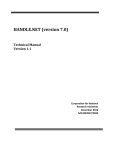
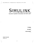
The following figure shows the top level of the model.
3-16
HDL Code Generation from a Simulink Model
This model uses a division of labor that is helpful in HDL design:
• The symmetric_fir subsystem, which implements the filter algorithm, is the
device under test (DUT). An HDL entity will be generated, tested, and eventually
synthesized from this subsystem.
• The top-level model components that drive the subsystem work as a test bench.
The top-level model generates 16-bit fixed-point input signals for the symmetric_fir
subsystem. The Signal From Workspace block generates a test input (stimulus) signal for
the filter. The four Constant blocks provide filter coefficients.
The Scope blocks are used in simulation only. They are virtual blocks, and do not
generate HDL code.
3-17
3
Tutorials
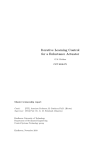
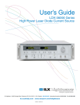
The following figure shows the symmetric_fir subsystem.
The fixed-point data types propagate through the subsystem. Inputs inherit the data
types of the signals presented to them. Where required, internal rules of the blocks
determine the output data type, given the input data types and the operation performed
(for example, the Product blocks).
The filter outputs a fixed-point result at the y_out port, and also replicates its input
(after passing it through several delay stages) at the delayed_x_out port.
In the exercises that follow, you generate VHDL code that implements the
symmetric_fir subsystem as an entity. You then generate a test bench from the top3-18
HDL Code Generation from a Simulink Model
level model. The test bench drives the generated entity, for the required number of clock
steps, with stimulus data generated from the Signal From Workspace block.
Generate Code Using the HDL Workflow Advisor
This example shows how to generate HDL code from a Simulink model using the HDL
Workflow Advisor.
The model you use in this example, sfir_fixed, is already prepared for code
generation.
This example uses the Xilinx ISE synthesis tool, and assumes your synthesis tool path is
set up. You can also follow this example using Altera Quartus II.
Create Working Folder and Copy Model
1
Start MATLAB.
2
Create a folder named sl_hdlcoder_work. For example:
mkdir C:\work\sl_hdlcoder_work
You will use sl_hdlcoder_work to store a local copy of the example model and to
store folders and code generated by HDL Coder. The location of the folder does not
matter, except that it should not be within the MATLAB folder tree.
3
Make the sl_hdlcoder_work folder your working folder. For example:
cd C:\work\sl_hdlcoder_work
4
Open the sfir_fixed model.
sfir_fixed
5
Save a copy of sfir_fixed in your sl_hdlcoder_work folder.
Generate Code Using the HDL Workflow Advisor
1
Right-click the symmetric_fir subsystem and select HDL Code > HDL
Workflow Advisor.
2
In the Set Target > Set Target Device and Synthesis Tool step, for Synthesis
tool, select Xilinx ISE and click Run This Task.
3-19
3
Tutorials
3
3-20
Right-click Prepare Model For HDL Code Generation and select Run All. The
HDL Workflow Advisor checks the model for code generation compatibility.
HDL Code Generation from a Simulink Model
4
In the HDL Code Generation > Set Code Generation Options > Set Basic
Options step, select the following options, then click Apply:
• For Language, select Verilog.
• Enable Generate traceability report.
• Enable Generate resource utilization report.
3-21
3
Tutorials
5
3-22
View the options available in the Optimization and Coding style tabs. You can
use these options to modify the implementation and format of the generated code.
HDL Code Generation from a Simulink Model
3-23
3
Tutorials
6
3-24
Right-click the HDL Code Generation > Generate RTL Code and Testbench
step, and select Run to Selected Task.
HDL Code Generation from a Simulink Model
The code generation report, which includes the resource utilization and traceability
reports, opens automatically. The resource utilization report shows the hardware
resources your design implementation is using. The traceability report enables you
to navigate between your model and the generated code.
3-25
3
Tutorials
Perform FPGA Synthesis and Analysis
3-26
1
In the FPGA Synthesis and Analysis > Perform Synthesis and P/R > Perform
Place and Route task, unselect Skip this task and click Apply.
2
Right-click Annotate Model with Synthesis Result and select Run to Selected
Task.
HDL Code Generation from a Simulink Model
3
View the annotated critical path in the model.
The critical path is colored cyan.
3-27
3
Tutorials
Generate HDL Code Using the Command Line
• “Overview” on page 3-29
• “Creating a Folder and Local Model File” on page 3-29
• “Initializing Model Parameters with hdlsetup” on page 3-29
• “Generating a VHDL Entity from a Subsystem” on page 3-31
• “Generating VHDL Test Bench Code” on page 3-32
• “Verifying Generated Code” on page 3-34
• “Generating a Verilog Module and Test Bench” on page 3-34
3-28
HDL Code Generation from a Simulink Model
Overview
This exercise provides a step-by-step introduction to code and test bench generation
commands, their arguments, and the files created by the code generator. The exercise
assumes that you have familiarized yourself with the example model (see “The sfir_fixed
Model” on page 3-16).
Creating a Folder and Local Model File
Make a local copy of the example model and store it in a working folder, as follows.
1
Start the MATLAB software.
2
Create a folder named sl_hdlcoder_work, for example:
mkdir C:\work\sl_hdlcoder_work
The sl_hdlcoder_work folder will store a local copy of the example model and to
store folders and code generated by HDL Coder. The location of the folder does not
matter, except that it should not be within the MATLAB tree.
3
Make the sl_hdlcoder_work folder your working folder, for example:
cd C:\work\sl_hdlcoder_work
4
To open the example model, type the following command at the MATLAB prompt:
sfir_fixed
5
In Simulink, select File > Save As and save a local copy of the sfir_fixed model
to your working folder.
6
Leave the sfir_fixed model open and proceed to the next section.
Initializing Model Parameters with hdlsetup
Before generating code, you must configure the model. You can use the hdlsetup
command instead of configuring the model manually. The hdlsetup command uses the
set_param function to set up models for HDL code generation quickly and consistently.
To configure the model for HDL code generation:
1
At the MATLAB command prompt, enter:
hdlsetup('sfir_fixed')
2
Select Save from the File menu, to save the model with its new settings.
3-29
3
Tutorials
Before continuing with code generation, consider the settings that hdlsetup applies to
the model.
hdlsetup configures the Solver options that are recommended or required by HDL
Coder. These are
• Type: Fixed-step. (HDL Coder currently supports variable-step solvers under
limited conditions. See hdlsetup)
• Solver: Discrete (no continuous states). Other fixed-step solvers could be
selected, but this option is usually the best one for simulating discrete systems.
• Tasking mode: SingleTasking. HDL Coder does not currently support models that
execute in multitasking mode.
Do not set Tasking mode to Auto.
hdlsetup also configures the model start and stop times and fixed-step size as follows:
• Start Time: 0.0 s
• Stop Time: 10 s
• Fixed step size (fundamental periodic sample time) : auto
If Fixed step size is set to auto the step size is chosen automatically, based on the
sample times specified in the model. In the example model, only the Signal From
Workspace block specifies an explicit sample time (1 s); the other blocks inherit this
sample time.
The model start and stop times determine the total simulation time. This in turn
determines the size of data arrays that are generated to provide stimulus and output
data for generated test benches. For the example model, computation of 10 seconds of
test data does not take a significant amount of time. Computation of sample values for
more complex models can be time consuming. In such cases, you may want to decrease
the total simulation time.
The remaining parameters set by hdlsetup control error severity levels, data logging,
and model display options. If you want to view the complete set of model parameters
affected by hdlsetup, open hdlsetup.m in the MATLAB Editor.
The model parameter settings provided by are intended as useful defaults, but they may
not be optimal for your application. For example, hdlsetup sets a default Simulation
stop time of 10 s. A total simulation time of 1000 s would be more realistic for a test of
3-30
HDL Code Generation from a Simulink Model
the sfir_fixed example model. If you would like to change the simulation time, enter
the desired value into the Simulation stop time field of the Simulink window.
See the “Model Parameters” table in the “Model and Block Parameters” section of the
Simulink documentation for a summary of model parameters.
Generating a VHDL Entity from a Subsystem
In this section, you will use the makehdl function to generate code for a VHDL entity
from the symmetric_fir subsystem of the example model. makehdl also generates
script files for third-party HDL simulation and synthesis tools.
makehdl lets you specify numerous properties that control various features of the
generated code. In this example, you will use the makehdl property defaults.
Before generating code, make sure that you have completed the steps described in
“Creating a Folder and Local Model File” on page 3-29 and “Initializing Model
Parameters with hdlsetup” on page 3-29.
To generate code:
1
Select Current Folder from the Desktop menu in the MATLAB window. This
displays the MATLAB Current Folder browser, which lets you easily access your
working folder and the files that will be generated within it.
2
At the MATLAB prompt, type the command
makehdl('sfir_fixed/symmetric_fir')
This command directs HDL Coder to generate code from the symmetric_fir
subsystem within the sfir_fixed model, using default property values.
3
As code generation proceeds, HDL Coder displays progress messages. The process
should complete with the message
### HDL Code Generation Complete.
Observe that the names of generated files in the progress messages are hyperlinked.
After code generation completes, you can click these hyperlinks to view the files in
the MATLAB Editor.
makehdl compiles the model before generating code. Depending on model display
options (such as port data types, etc.), the appearance of the model may change after
code generation.
3-31
3
Tutorials
4
By default, makehdl generates VHDL code. Code files and scripts are written to a
target folder. The default target folder is a subfolder of your working folder, named
hdlsrc.
A folder icon for the hdlsrc folder is now visible in the Current Folder browser. To
view generated code and script files, double-click the hdlsrc folder icon.
5
The files that makehdl has generated in the hdlsrc folder are
• symmetric_fir.vhd: VHDL code. This file contains an entity definition and
RTL architecture implementing the symmetric_fir filter.
• symmetric_fir_compile.do: Mentor Graphics ModelSim compilation script
(vcom command) to compile the generated VHDL code.
• symmetric_fir_synplify.tcl: Synplify® synthesis script
• symmetric_fir_map.txt: Mapping file. This report file maps generated
entities (or modules) to the subsystems that generated them (see “Trace Code
Using the Mapping File”).
6
To view the generated VHDL code in the MATLAB Editor, double-click the
symmetric_fir.vhd file icon in the Current Folder browser.
7
Before proceeding to the next section, close files you have opened in the editor. Then,
click the Go Up One Level button in the Current Folder browser, to set the current
folder back to your sl_hdlcoder_work folder.
8
Leave the sfir_fixed model open and proceed to the next section.
Generating VHDL Test Bench Code
In this section, you use the test bench generation function, makehdltb, to generate a
VHDL test bench. The test bench is designed to drive and verify the operation of the
symmetric_fir entity that was generated in the previous section. A generated test
bench includes
• Stimulus data generated by signal sources connected to the entity under test.
• Output data generated by the entity under test. During a test bench run, this data is
compared to the outputs of the VHDL model, for verification purposes.
• Clock, reset, and clock enable inputs to drive the entity under test.
• A component instantiation of the entity under test.
• Code to drive the entity under test and compare its outputs to the expected data.
3-32
HDL Code Generation from a Simulink Model
In addition, makehdltb generates Mentor Graphics ModelSim scripts to compile and
execute the test bench.
This exercise assumes that your working folder is the same as that used in the previous
section. This folder now contains an hdlsrc folder containing the previously generated
code.
To generate a test bench:
1
At the MATLAB prompt, type the command
makehdltb('sfir_fixed/symmetric_fir')
This command generates a test bench that is designed to interface to and validate
code generated from symmetric_fir (or from a subsystem with a functionally
identical interface). By default, VHDL test bench code, as well as scripts, are
generated in the hdlsrc target folder.
2
As test bench generation proceeds, HDL Coder displays progress messages. The
process should complete with the message
### HDL TestBench Generation Complete.
3
To view generated test bench and script files, double-click the hdlsrc folder icon in
the Current Folder browser. Alternatively, you can click the hyperlinked names of
generated files in the code test bench generation progress messages.
The files generated by makehdltb are:
• symmetric_fir_tb.vhd: VHDL test bench code and generated test and output
data.
• symmetric_fir_tb_compile.do: Mentor Graphics ModelSim
compilation script (vcom commands). This script compiles and loads both
the entity to be tested (symmetric_fir.vhd) and the test bench code
(symmetric_fir_tb.vhd).
• symmetric_fir_tb_sim.do: Mentor Graphics ModelSim script to initialize the
simulator, set up wave window signal displays, and run a simulation.
4
If you want to view the generated test bench code in the MATLAB Editor, doubleclick the symmetric_fir.vhd file icon in the Current Folder browser. You may
want to study the code while referring to the makehdltb reference documentation,
which describes the default actions of the test bench generator.
3-33
3
Tutorials
5
Before proceeding to the next section, close files you have opened in the editor. Then,
click the Go Up One Level button in the Current Folder browser, to set the current
folder back to your sl_hdlcoder_work folder.
Verifying Generated Code
You can now take the previously generated code and test bench to an HDL simulator for
simulated execution and verification of results. See “Simulating and Verifying Generated
HDL Code” on page 3-46 for an example of how to use generated test bench and script
files with the Mentor Graphics ModelSim simulator.
Generating a Verilog Module and Test Bench
The procedures for generating Verilog code differ only slightly from those for generating
VHDL code. This section provides an overview of the command syntax and the generated
files.
Generating a Verilog Module
By default, makehdl generates VHDL code. To override the default and generate Verilog
code, you must pass in a property/value pair to makehdl, setting the TargetLanguage
property to 'verilog', as in this example.
makehdl('sfir_fixed/symmetric_fir','TargetLanguage','verilog')
The previous command generates Verilog source code, as well as scripts for the
simulation and the synthesis tools, in the default target folder, hdlsrc.
The generated files are:
• symmetric_fir.v: Verilog code. This file contains a Verilog module implementing
the symmetric_fir subsystem.
• symmetric_fir_compile.do: Mentor Graphics ModelSim compilation script (vlog
command) to compile the generated Verilog code.
• symmetric_fir_synplify.tcl: Synplify synthesis script.
• symmetric_fir_map.txt: Mapping file. This report file maps generated entities (or
modules) to the subsystems that generated them (see “Trace Code Using the Mapping
File”).
3-34
HDL Code Generation from a Simulink Model
Generating and Executing a Verilog Test Bench
The makehdltb syntax for overriding the target language is exactly the same as that for
makehdl. The following example generates Verilog test bench code to drive the Verilog
module, symmetric_fir, in the default target folder.
makehdltb('sfir_fixed/symmetric_fir','TargetLanguage','verilog')
The generated files are:
• symmetric_fir_tb.v: Verilog test bench code and generated test and output data.
• symmetric_fir_tb_compile.do: Mentor Graphics ModelSim compilation script
(vlog commands). This script compiles and loads both the entity to be tested
(symmetric_fir.v) and the test bench code (symmetric_fir_tb.v).
• symmetric_fir_tb_sim.do: Mentor Graphics ModelSim script to initialize the
simulator, set up wave window signal displays, and run a simulation.
The following listing shows the commands and responses from a test bench session using
the generated scripts:
ModelSim> do symmetric_fir_tb_compile.do
# Model Technology ModelSim SE vlog 6.0 Compiler 2004.08 Aug 19 2004
# -- Compiling module symmetric_fir
#
# Top level modules:
# symmetric_fir
# Model Technology ModelSim SE vlog 6.0 Compiler 2004.08 Aug 19 2004
# -- Compiling module symmetric_fir_tb
#
# Top level modules:
# symmetric_fir_tb
ModelSim>do symmetric_fir_tb_sim.do
# vsim work.symmetric_fir_tb
# Loading work.symmetric_fir_tb
# Loading work.symmetric_fir
# **** Test Complete. ****
# Break at
C:/work/sl_hdlcoder_work/vlog_code/symmetric_fir_tb.v line 142
# Simulation Breakpoint:Break at
C:/work/sl_hdlcoder_work/vlog_code/symmetric_fir_tb.v line 142
# MACRO ./symmetric_fir_tb_sim.do PAUSED at line 14
Generate HDL Code Using the Configuration Parameters Dialog Box
• “HDL Coder GUI Overview” on page 3-36
• “Creating a Folder and Local Model File” on page 3-38
3-35
3
Tutorials
• “Viewing Coder Options in the Configuration Parameters Dialog Box” on page
3-39
• “Initializing Model Parameters with hdlsetup” on page 3-40
• “Selecting and Checking a Subsystem for HDL Compatibility” on page 3-42
• “Generating VHDL Code” on page 3-42
• “Generating VHDL Test Bench Code” on page 3-44
• “Verifying Generated Code” on page 3-46
• “Generating Verilog Model and Test Bench Code” on page 3-46
HDL Coder GUI Overview
You can view and edit options and parameters that affect HDL code generation in the
Configuration Parameters dialog box, or in the Model Explorer.
The following figure shows the top-level HDL Code Generation pane in the
Configuration Parameters dialog box.
3-36
HDL Code Generation from a Simulink Model
The following figure shows the top-level HDL Code Generation options pane in the
Model Explorer.
3-37
3
Tutorials
In the code generation exercises that follow, you use the Configuration Parameters
dialog box to view and set HDL Coder options and controls. The exercises use the
sfir_fixed model (see “The sfir_fixed Model” on page 3-16) in basic code generation
and verification steps.
Creating a Folder and Local Model File
In this section you will setup the folder and a local copy of the example model.
Creating a Folder
Start by setting up a working folder:
1
Start MATLAB.
2
Create a folder named sl_hdlcoder_work, for example:
mkdir C:\work\sl_hdlcoder_work
3-38
HDL Code Generation from a Simulink Model
You will use sl_hdlcoder_work to store a local copy of the example model and to
store folders and code generated by HDL Coder. The location of the folder does not
matter, except that it should not be within the MATLAB folder tree.
3
Make the sl_hdlcoder_work folder your working folder, for example:
cd C:\work\sl_hdlcoder_work
Making a Local Copy of the Model File
Next, make a copy of the sfir_fixed model:
1
To open the model, type the following command at the MATLAB prompt:
sfir_fixed
2
Save a local copy of the sfir_fixed model to your working folder.
3
Leave the sfir_fixed model open and proceed to the next section.
Viewing Coder Options in the Configuration Parameters Dialog Box
HDL Coder option settings are displayed as a category of the model's active configuration
set. You can view and edit these options in the Configuration Parameters dialog box, or
in the Model Explorer. This discussion uses the Configuration Parameters dialog box.
To access HDL Coder settings:
1
Open the Configuration Parameters dialog box.
2
Select the HDL Code Generation pane.
3-39
3
Tutorials
The HDL Code Generation pane contains top-level options and buttons that
control the HDL code generation process. Several other categories of options are
available under the HDL Code entry. This exercise uses a small subset of these
options, leaving the others at their default settings.
Initializing Model Parameters with hdlsetup
Before generating code, you must set some parameters of the model. Rather than
doing this manually, use the hdlsetup command. The hdlsetup command uses the
set_param function to set up models for HDL code generation quickly and consistently.
To set the model parameters:
3-40
HDL Code Generation from a Simulink Model
1
At the MATLAB command prompt, type:
hdlsetup('sfir_fixed')
2
Save the model with its new settings.
Before continuing with code generation, consider the settings that hdlsetup applies to
the model.
hdlsetup configures Solver options that are recommended or required by HDL Coder.
These options are:
• Type: Fixed-step. (HDL Coder currently supports variable-step solvers under
limited conditions. See hdlsetup.)
• Solver: Discrete (no continuous states). Other fixed-step solvers could be
selected, but this option is usually the best one for simulating discrete systems.
• Tasking mode: SingleTasking. HDL Coder does not currently support models that
execute in multitasking mode.
Do not set Tasking mode to Auto.
hdlsetup also configures the model start and stop times and fixed-step size as follows:
• Start Time: 0.0 s
• Stop Time: 10 s
• Fixed step size (fundamental periodic sample time): auto
If Fixed step size is set to auto the step size is chosen automatically, based on the
sample times specified in the model. In the example model, only the Signal From
Workspace block specifies an explicit sample time (1 s); the other blocks inherit this
sample time.
The model start and stop times determine the total simulation time. This in turn
determines the size of data arrays that are generated to provide stimulus and output
data for generated test benches. For the example model, computation of 10 seconds of
test data does not take a significant amount of time. Computation of sample values for
more complex models can be time consuming. In such cases, you may want to decrease
the total simulation time.
The remaining parameters set by hdlsetup control error severity levels, data logging,
and model display options. If you want to view the complete set of model parameters
affected by hdlsetup, open hdlsetup.m in the MATLAB Editor.
3-41
3
Tutorials
The model parameter settings provided by hdlsetup are intended as useful defaults,
but they may not be optimal for your application. For example, hdlsetup sets a default
Simulation stop time of 10 s. A total simulation time of 1000 s would be more realistic
for a test of the sfir_fixed example model. If you would like to change the simulation
time, enter the desired value into the Simulation stop time field of the Simulink
Editor.
See the “Model Parameters” table in the “Model and Block Parameters” section of the
Simulink documentation for a summary of model parameters.
Selecting and Checking a Subsystem for HDL Compatibility
HDL Coder generates code from either the current model or from a subsystem at the root
level of the current model. You use the Generate HDL for menu to select the model or
subsystem from which code is to be generated. Each entry in the menu shows the full
path to the model or one of its subcomponents.
The sfir_fixed model is configured with the sfir_fixed/symmetric_fir subsystem
selected for code generation. If this is not the case, make sure that the symmetric_fir
subsystem is selected for code generation, as follows:
1
Select sfir_fixed/symmetric_fir from the Generate HDL for menu.
2
Click Apply.
To check HDL compatibility for the subsystem:
1
Click the Run Compatibility Checker button.
2
The HDL compatibility checker examines the system selected in the Generate HDL
for menu for compatibility problems. In this case, the selected subsystem is fully
HDL-compatible, and the compatibility checker displays the following message:
### Starting HDL Check.
### HDL Check Complete with 0 errors, warnings and messages.
The compatibility checker also displays a report in a new window.
Generating VHDL Code
The top-level HDL Code Generation options are now set as follows:
• The Generate HDL for field specifies the sfir_fixed/symmetric_fir subsystem
for code generation.
3-42
HDL Code Generation from a Simulink Model
• The Language field specifies (by default) generation of VHDL code.
• The Folder field specifies a target folder that stores generated code files and scripts.
The default target folder is a subfolder of your working folder, named hdlsrc.
Before generating code, select Current Folder from the Desktop menu in the MATLAB
window. This displays the Current Folder browser, which lets you access your working
folder and the files that will be generated within it.
To generate code:
1
Click the Generate button.
2
As code generation proceeds, HDL Coder displays progress messages. The process
should complete with the message
3-43
3
Tutorials
### HDL Code Generation Complete.
Observe that the names of generated files in the progress messages are hyperlinked.
After code generation completes, you can click these hyperlinks to view the files in
the MATLAB Editor.
HDL Coder compiles the model before generating code. Depending on model display
options (such as port data types, etc.), the appearance of the model may change after
code generation.
3
A folder icon for the hdlsrc folder is now visible in the Current Folder browser. To
view generated code and script files, double-click the hdlsrc folder icon.
4
The files that were generated in the hdlsrc folder are:
• symmetric_fir.vhd: VHDL code. This file contains an entity definition and
RTL architecture implementing the symmetric_fir filter.
• symmetric_fir_compile.do: Mentor Graphics ModelSim compilation script
(vcom command) to compile the generated VHDL code.
• symmetric_fir_synplify.tcl: Synplify synthesis script.
• symmetric_fir_map.txt: Mapping file. This report file maps generated
entities (or modules) to the subsystems that generated them (see “Trace Code
Using the Mapping File”).
5
To view the generated VHDL code in the MATLAB Editor, double-click the
symmetric_fir.vhd file icon in the Current Folder browser.
6
Before proceeding to the next section, close files you have opened in the editor. Then,
click the Go Up One Level button in the Current Folder browser, to set the current
folder back to your sl_hdlcoder_work folder.
Generating VHDL Test Bench Code
At this point, the Generate HDL for, Language, and Folder fields are set as they
were in the previous section. Accordingly, you can now generate VHDL test bench code
to drive the VHDL code generated previously for the sfir_fixed/symmetric_fir
subsystem. The code will be written to the same target folder as before.
To generate a VHDL test bench:
1
3-44
Select the HDL Code Generation > Test Bench pane.
HDL Code Generation from a Simulink Model
2
Select HDL test bench.
3
Click the Generate Test Bench button.
4
As test bench generation proceeds, HDL Coder displays progress messages. The
process should complete with the message
### HDL TestBench Generation Complete.
5
The generated files in the hdlsrc folder are:
• symmetric_fir_tb.vhd: VHDL test bench code, with generated test and output
data.
3-45
3
Tutorials
• symmetric_fir_tb_compile.do: Mentor Graphics ModelSim compilation
script (vcom commands). This script compiles and loads the entity to be tested
(symmetric_fir.vhd) and the test bench code (symmetric_fir_tb.vhd).
• symmetric_fir_tb_sim.do: Mentor Graphics ModelSim script to initialize the
simulator, set up wave window signal displays, and run a simulation.
Verifying Generated Code
You can now take the generated code and test bench to an HDL simulator for simulated
execution and verification of results. See “Simulating and Verifying Generated HDL
Code” on page 3-46 for an example of how to use generated test bench and script files
with the Mentor Graphics ModelSim simulator.
Generating Verilog Model and Test Bench Code
The procedure for generating Verilog code is the same as for generating VHDL code (see
“Generating a VHDL Entity from a Subsystem” on page 3-31 and “Generating VHDL
Test Bench Code” on page 3-32), except that you select Verilog from the Language
field of the HDL Code Generation options.
Simulating and Verifying Generated HDL Code
Note: This section requires the use of the Mentor Graphics ModelSim simulator.
This section assumes that you have generated code from the sfir_fixed model as
described in either of the following exercises:
• “Generate HDL Code Using the Command Line” on page 3-28
• “Generate HDL Code Using the Configuration Parameters Dialog Box” on page
3-35
In this section you compile and run a simulation of the previous generated model and
test bench code. The scripts generated by HDL Coder let you do this with just a few
simple commands. The procedure is the same, whether you generated code in the
command line environment or in the GUI.
To run the simulation:
1
3-46
Start the Mentor Graphics ModelSim software.
HDL Code Generation from a Simulink Model
2
Set the working folder to the folder in which you previously generated code.
ModelSim>cd C:/work/sl_hdlcoder_work/hdlsrc
3
Use the generated compilation script to compile and load the generated model and
text bench code. The following listing shows the command and responses.
ModelSim>do symmetric_fir_tb_compile.do
# Model Technology ModelSim SE vcom 6.0 Compiler 2004.08 Aug 19 2004
# -- Loading package standard
# -- Loading package std_logic_1164
# -- Loading package numeric_std
# -- Compiling entity symmetric_fir
# -- Compiling architecture rtl of symmetric_fir
# Model Technology ModelSim SE vcom 6.0 Compiler 2004.08 Aug 19 2004
# -- Loading package standard
# -- Loading package std_logic_1164
# -- Loading package numeric_std
# -- Compiling package symmetric_fir_tb_pkg
# -- Compiling package body symmetric_fir_tb_pkg
# -- Loading package symmetric_fir_tb_pkg
# -- Loading package symmetric_fir_tb_pkg
# -- Compiling entity symmetric_fir_tb
# -- Compiling architecture rtl of symmetric_fir_tb
# -- Loading entity symmetric_fir
4
Use the generated simulation script to execute the simulation. The following listing
shows the command and responses. The warning messages are benign.
ModelSim>do symmetric_fir_tb_sim.do
# vsim work.symmetric_fir_tb
# Loading C:\Applications\ModelTech_6_0\win32/../std.standard
# Loading C:\Applications\ModelTech_6_0\win32/../ieee.std_logic_1164(body)
# Loading C:\Applications\ModelTech_6_0\win32/../ieee.numeric_std(body)
# Loading work.symmetric_fir_tb_pkg(body)
# Loading work.symmetric_fir_tb(rtl)
# Loading work.symmetric_fir(rtl)
# ** Warning: NUMERIC_STD."<": metavalue detected, returning FALSE
#
Time: 0 ns Iteration: 0 Instance: /symmetric_fir_tb
.
.
.
# ** Warning: NUMERIC_STD.TO_INTEGER: metavalue detected, returning 0
#
Time: 0 ns Iteration: 1 Instance: /symmetric_fir_tb
# ** Note: **************TEST COMPLETED **************
#
Time: 140 ns Iteration: 1 Instance: /symmetric_fir_tb
The test bench termination message indicates that the simulation has run to
completion without comparison errors.
# ** Note: **************TEST COMPLETED **************
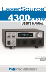
5
The simulation script displays inputs and outputs in the model (including the
reference signals y_out_ref and delayed_x_out_ref) in the Mentor Graphics
ModelSim wave window. The following figure shows the signals displayed in the
wave window.
3-47
3
Tutorials
3-48
6
Exit the Mentor Graphics ModelSim simulator when you finish viewing signals.
7
Close files you have opened in the MATLAB Editor. Then, click the Go Up One
Level button in the Current Folder browser, to set the current folder back to your
work folder.