1
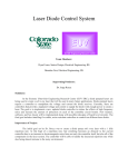
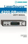
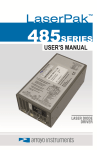
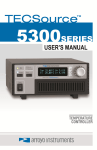
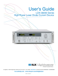
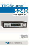
Page 2 · 4300 Series LaserSource User’s Manual Table of Contents Introduction ............................................................................................... 3 Safety Terms and Symbols ....................................................................... 5 Quick Start ................................................................................................ 7 Installation ................................................................................................. 8 Operation ................................................................................................ 10 Settings and Menus ................................................................................ 12 Control Modes......................................................................................... 17 Using QCW Modes ................................................................................. 18 Cable Wiring for Modulation and QCW .................................................. 20 Using the Cable R Setting ....................................................................... 21 Using Remote Voltage Sense (4320 Only) ............................................. 22 Remote Mode Operation......................................................................... 23 Installing the USB Drivers ....................................................................... 23 Rear Panel ............................................................................................... 24 Connecting to the LaserSource .............................................................. 27 Grounding Considerations ...................................................................... 28 Using Limits............................................................................................. 28 Thermal Considerations .......................................................................... 29 Specifications .......................................................................................... 30 Error Messages ....................................................................................... 32 Maintenance and Service........................................................................ 33 Warranty .................................................................................................. 34 4300 Series LaserSource User’s Manual · Page 3 Introduction Thank you for choosing the LaserSource from Arroyo Instruments. Your LaserSource is a combination of leading edge technology combined with years of experience in the field of current control. With a crystal clear VFD display, both RS232 and USB computer interfaces, and small footprint, the LaserSource will fit into almost any laser diode control application. A key feature of the LaserSource is its optical isolation of both modulation and photodiode inputs. By isolating these inputs, it prevents unwanted ground loop problems. No other laser diode driver in the industry has this feature. Another important feature of the LaserSource is its ability to operate in quasiCW (QCW) mode. This mode permits operation of lasers to a higher current and power, minimizing the thermal load by turning the laser on for only a brief period of time, taking measurements, then turning off the laser. The LaserSource supports both internal and external triggering of pulses, and also includes a trigger out to synchronize the LaserSource with other instruments. The LaserSource also operates in constant voltage control mode, allowing you to use it in precision voltage applications, such as EML devices, or for doing V-I measurement graphs. The LaserSource includes another feature not found in other products: the ability to program the photodiode bias level from the front panel or over the computer interface, to any voltage from 0 to -5V. No more tweaking a potentiometer with a screwdriver and a DMM. Simply dial in the voltage you need. Unlike other laser diode drivers in its class, which use inexpensive 7-segment displays, the LaserSource takes advantage of its large VFD display to simultaneously show the set point, laser voltage, and photodiode read back. The user interface of the LaserSource is engineered to make using the instrument straightforward. With its text-based menus, there is never any confusion over which setting is being changed, and parameters are displayed in clear English (no cryptic numbers or LEDs to decode). The LaserSource offers all the features you would expect from a modern precision laser diode driver, including: Page 4 · 4300 Series LaserSource User’s Manual 10ppm current stability over one hour 2A to 20A current ranges Comprehensive laser protection circuitry, including hardware voltage and current limits, and fast transient shutdown. External analog modulation Power mode control, both in photodiode current (AMC) or computed photodiode power (APC) modes. Simultaneous reading of current set point, voltage measurement, and photodiode current or power measurement. What’s in the Box Along with the LaserSource itself, a CD with electronic copies of this manual, the Computer Interfacing Manual, and USB drivers are included. For USA customers, a power cord is included. For non-USA customers, an IEC-60320C13 rated AC power cord must be provided. Accessories Arroyo Instruments also sells several accessories designed to work with the LaserSource. These include: LaserSource Cable, 2m (p/n 1220B) This cable has DB-9 male/female connectors for interfacing to the LaserMount or other connectorized fixtures. LaserSource Cable, 2m, Pigtailed (p/n 1221B) This cable has a female DB-9 connector for plugging into the LaserSource and tinned leads for wiring into custom solutions. LaserSource Cable, 20A, 9W4, 2m (p/n 1228B) Design for the 4320’s 9W4 connector, this cable is designed for 20A operation, and has 9W4 male/female connectors. LaserSource Cable, 20A, 9W4, Pigtailed, 2m (p/n 1229B) Design for the 4320’s 9W4 connector, this cable is designed for 20A operation, and has 9W4 male connector on the instrument end and bare wire leads connections on the device end for custom wiring. LaserSource Cable, Sensor, DB-9, 2m (p/n 1228-S) Designed for the 4320’s Sensor / Interlock connector, this cable has DB-9 male and female connectors, and carries the photodiode and remote voltage sense signals. 4300/5300 Series 2U Rack Mount Kit, 1 unit (p/n 1401-RM-1) 4300/5300 Series 2U Rack Mount Kit, 2 units (p/n 1401-RM-2) For installing your 5300 Series TECSource or 4300 LaserSource into a standard 19” rack. The 1401-RM-1 is used when installing a single instrument into a 2U rack space. For mounting two instruments side-byside, use the 1401-RM-2 rack mount kit. A 1401-RM-1 cannot be 4300 Series LaserSource User’s Manual · Page 5 converted to a 1401-RM-2, or vise versa, to be sure to purchase the correct rack mount kit. RS-232 NULL Cable, 3m (p/n 1200-NULL) USB Cable, 3m (p/n 1201) Safety Terms and Symbols The following safety-related terms are used in this manual: Warnings (noted by the WARNING heading) explain dangers that could result in physical injury or death; Cautions (noted by the CAUTION heading) explain conditions that could result in damage to the instrument, other equipment, or your device. Notes (noted by the NOTES heading) are not safety-related, and are intended simply to point out important information. If, at any time, any of the following conditions exist, or are suspected of existing, discontinue use of the unit until it can be inspected by qualified service personnel: Visible damage to the unit, including damage or stress caused during product shipment; Storage of the unit outside the standard storage temperature or humidity rating, or prolonged storage under harsh conditions; Failure to operate properly. If needed, contact your distributor or Arroyo Instruments for service or repair to ensure the safety of the product is maintained. Symbols Power Off Power On Caution, refer to manual Earth ground Caution, risk of electric shock Page 6 · 4300 Series LaserSource User’s Manual General Warnings WARNING Potentially lethal voltages exist within this instrument. This instrument is intended for use by qualified personnel who understand the shock and laser hazards and are familiar with safety procedures required to avoid injury. Read this manual completely before attempting to use this product. WARNING To avoid electrical shock, ensure a 3-prong power cord is used, and is plugged into a earth-grounded receptacle. Failure to do so can result in severe injury or death. CAUTION There are no user-serviceable parts inside. All service and repair work shall be done by Arroyo Instruments or personnel authorized by Arroyo Instruments. Modifications done by non-authorized personnel will void the warranty. Please see the Service section later in this manual for instructions on how to obtain service for this instrument. 4300 Series LaserSource User’s Manual · Page 7 Quick Start The LaserSource was designed with ease of use in mind, and you will likely have little need for this manual for almost all of the features the unit offers. This section will show how you can quickly get the unit up and running in almost no time. After unpacking the unit, ensure that the voltage selection on the Input Power Connector (IPC) on the back of the unit is set to the correct voltage. This is critical, as incorrect voltages can damage the unit. The LaserSource is typically shipped in the 120V configuration from the factory, but always verify the voltage selection. Change the voltage as needed. For more information, refer to the IPC section below. Once the voltage selection has been completed, plug the AC cord into the unit and into the wall outlet. Turn on the power switch located on the front panel, and the unit will power up, displaying the model information, serial number, and firmware version number. Press the Menu button to enter the menu, and using the knob, turn to the right until the Io Lim setting is displayed. Press the knob to edit the setting, and adjust the limit as appropriate to your laser diode. Press the knob again to save the value. Make the same adjustments to the voltage limit (Vf Lim), as appropriate for your application. Once you have made all your adjustments, press the Menu button to exit the menu. Next, connect the cable between your LaserMount or other fixture and the Output connector of the LaserSource. We recommend using our cables as they have been designed to work well with the LaserSource. If using your own cables, ensure they have been properly wired according to the pin-out of the LaserSource and your fixture. Finally, set the set point to an appropriate current and press the Output button. The output will turn on and you will see the actual voltage and photodiode current displayed on the second line. It’s that simple. For more detailed operating and installation instructions, read on. Page 8 · 4300 Series LaserSource User’s Manual Installation Installation of the LaserSource is very straightforward, as the quick start section above illustrated. This section will provide additional details and considerations for installing your LaserSource. After unpacking the unit, make sure all packing materials have been removed and nothing obscures the ventilation ports on the side and front of the unit. Changing the Voltage Selection Before powering on the unit, ensure that the voltage selection on the IPC is set correctly. Improper voltage selection can easily damage the unit. Changing the voltage selection requires that you remove the voltage selection module from the IPC. You can select from 100V, 120V, and 230V. Choose the voltage that most closely matches your AC voltage. Remove the power cord from the unit. Using a small, flat-blade screwdriver, insert the tip of the screwdriver into the two small openings above and below the voltage indication to release the voltage selection module from the IPC, as shown in the picture below. Input Power Connector (IPC) Once the module has been removed, remove the small, white voltage selection tumbler from the module, and then re-insert so that the desired voltage is shown. Re-insert the module into the IPC. 4300 Series LaserSource User’s Manual · Page 9 CAUTION Do not exceed 250VAC on the line input. It is critical to select the proper voltage selection prior to applying power to the unit. If the actual voltage exceeds the voltage selection by +/-10%, damage to the unit may occur. Powering Up the Unit Once the correct voltage selection has been made, connect the AC power cord to the unit. You must properly ground the unit by plugging the supplied power cord into a three prong grounded outlet, or using a three-to-two prong adapter and connecting the ground tab to earth ground. Turn the power switch, located on the front panel, into the on (|) position. The unit will display the model, serial number, and firmware version, go through a quick power-up self-test, and return to the last known operating state. Ventilation The LaserSource has vent holes on the side and front of the unit. You must not block these vent holes, or overheating may occur, causing damage to the unit. CAUTION Do not operate the unit above +40°C ambient, and ensure the instrument is properly ventilated, or the unit may overheat and possible damage to the unit may occur. Rack Mounting Rack mounting kits (p/n 1401-RM-1 or p/n 1401-RM-2) for standard 19” racks are available for the LaserSource, and supports the rack mount of one (1401RM-1) or two (1401-RM-2) units in a 2U (3.5”) high opening. Because the unit draws air from the side, and therefore inside the rack housing, be sure that the internal rack ambient temperature (which will typically be several degrees higher than room ambient) does not exceed the unit’s operating temperature. When using 1401-RM-2 to rack mount two units, either unit may also be a 5300 Series TECSource. Page 10 · 4300 Series LaserSource User’s Manual Warm-up and Environmental Considerations In order to achieve the highest level of accuracy, the LaserSource should be powered on for at least one hour prior to taking measurements. In addition, ensure that the unit is not operating outside the ambient temperature range or humidity conditions. Operation The Front Panel Operation of the LaserSource is very straightforward. The sections below will help familiarize you with the front panel, the display, and the menu structure. The front panel is designed for simplicity in operation. There are four buttons on the front panel: Output, Menu, adjustment knob, and the AC power switch. The output is controlled via the Output button. When turning the output on, there is a programmable delay (factory default of 3 seconds) where the unit will indicate that the output is on (the blue output LED will be lit), but the output stage is, in fact, not on. This is a CDRH safety feature required for some laser applications. The output will be energized once the delay has expired. The Menu button is used to enter the LaserSource menu. When in remote mode, it acts as a Local button, returning the instrument to local mode. The adjustment knob located on the right hand side of the unit is used to change the set point or parameters in the menu. It also acts as a push button, primarily as an enter button, when making changes in the menu. There are four LEDs: a green power LED that is lit whenever the AC power is turned on; the blue Output on LED that indicates the LaserSource is actively 4300 Series LaserSource User’s Manual · Page 11 controlling the laser diode; a red Error LED that indicates an error has occurred; and a yellow Remote LED that indicates the unit is being controlled via a computer. Whenever an error is generated, the red Error LED will light, and the error will be displayed on the VFD display. There may be one or more errors, but only the first error will be displayed. To display the next error, press Menu button. To clear all errors, press the knob. A list of error codes can be found in the Error Messages section below. When the unit is in remote mode, the yellow Remote LED will be lit. More information about how the instrument behaves in remote mode can be found in the Remote Mode Operation section below. Main Display Screen On the main display you will find the set point and two measurements. Which set point and measurements are displayed will depend on the control mode you have selected. An example display is shown below: Sample Display Measurements One of the advantages of the LaserSource is its ability to display both the set point and two measurements simultaneously. The table below shows which values will appear on the display depending on the mode selected: Mode Io Im Po Vf Setpoint Current (mA) PD current (μA) PD power (mW) Voltage (V) Displayed Measurements PD current or power and voltage Current and voltage Current and voltage Current and PD current or power The instrument will show photodiode current or photodiode power, depending on the value of PD Resp. Photodiode current is shown whenever PD Resp is zero, while photodiode power will be shown whenever PD Resp is non-zero. See the Control Modes section below for more information on the various modes. Page 12 · 4300 Series LaserSource User’s Manual Status Messages The instrument will display status messages in the upper-right corner of the display indicating several different conditions that may be of interest to the user. If multiple conditions exist simultaneously, then the instrument will cycle through each condition, displaying each status message for approximately one second. Possible condition messages are: HiBW Pulse ExtTrig Burst Lock Shrt OutT ILim MLim PLim The unit is in Io (HiBW) mode. The unit is in Io (Pulse) mode. The unit is in Io (Ext Trig) mode. The unit is in Io (Burst) mode. The interlock is open and the unit cannot be turned on. A short circuit has been detected on the output. The unit is out-of-tolerance. See the Tol Time and Tol Io settings for more information. The unit is in current limit. The unit is in photodiode current limit. The unit is in photodiode power limit. Notice that the mode indicators are in reverse text, and are used to highlight the operating mode. Settings and Menus All parameters of the LaserSource can be viewed and changed within the menu. The menus are constructed with the most used parameters first. To change any setting, press Menu to enter the menu then rotate the knob to select the parameter to change. Press the knob to begin changing the value. As a visual indication that you are in edit mode, you will see an asterisk appear next to the value. Once you have made your change, press the knob or Menu button to store the value. Pressing the Menu button will store and exit the menu, while pressing the knob will store the value but leave you in the menu to make additional changes. Some settings are contained inside a sub menu, such as communications settings. To access the sub menu, simply press the knob to enter the sub menu when its name is displayed. 4300 Series LaserSource User’s Manual · Page 13 Menu Description Root Menu Top Level Menu Factory Default Mode As described in the Control Modes section above, the unit offers seven control modes: Io (ACC), Io HiBW (ACC), Io (Pulse), Io (Ext Trig), Io (Burst), Im (AMC), Po (APC), and Vf (AVC). Change this setting to select a new mode. Io (ACC) QCW Const When in Io (Pulse) or Io (Burst) mode, this controls which parameter (frequency or duty cycle) is adjusted when the pulse width is adjusted. This setting will only be displayed when in Io (Pulse) or Io (Burst) modes. Freq QCW Width Sets the pulse width in QCW mode. See QCW Mode below for more details. This setting will only be displayed when in Io (Pulse), Io (Ext Trig), or Io (Burst) modes. 0.1ms QCW Duty Sets the duty cycle in QCW mode. See QCW Mode below for more details. This setting will only be displayed when in Io (Pulse) or Io (Burst) modes. 10% QCW Freq Sets the frequency of the QCW pulse. See QCW Mode below for more details. This setting will only be displayed when in Io (Pulse) or Io (Burst) modes. 1000 Hz QCW Pulses Sets the number of pulses to generate when in Io (Burst) mode. This setting will only be displayed when in Io (Burst) mode. 1 DelayIn Sets the delay, in seconds, from the start of trigger input pulse to the start of the current pulse. This setting will only be displayed when in Io (Ext Trig) mode. 0.000015s DelayOut Sets the delay, in seconds, from the current pulse to the start of the trigger output pulse. This setting will only be displayed when in Io (Pulse), Io (Ext Trig), or Io (Burst) modes. 0.000000s Io limit This setting controls the maximum amount of forward current that can be delivered to the laser diode. This limit is implemented in hardware for immediate response. For more information about limits, see Using Limits below. Maximum Page 14 · 4300 Series LaserSource User’s Manual Menu Description Factory Default Im limit This setting controls the maximum amount of monitor photodiode current the unit will allow. This limit is implemented in software. For more information about limits, see Using Limits below. Maximum Po limit This setting controls the maximum amount of monitor photodiode power the unit will allow. This limit is implemented in software. For more information about limits, see Using Limits below. Maximum Vf limit This setting controls the maximum amount of forward voltage that can be delivered to the laser diode. This limit is implemented in hardware for immediate response. For more information about limits, see Using Limits below. Maximum Vf Sense Selects the remote voltage sense lines for diode voltage measurement. Pins 4 & 5 of the Monitor / Interlock connector must be wiring to the diode. See Using Remote Voltage Sense below for more details. Only available on the 4320. Internal Sense Warn When operating in remote voltage sense mode, if the remote voltage is significantly lower that the voltage at the Output connector, a warning message is displayed. Only available when Vf Sense is set to External. Only available on the 4320. Yes Cable R The cable resistance, in ohms. This setting can be used to compensate for voltage losses in the cable due to cable and connector resistances. Cable R is ignored in Vf (AVC) Mode. For more information about this feature, see Using the Cable R Setting below. Not available when using remote voltage sense. 0.0000 Ω Int Contact Enables or disables intermittent contact. Not available in Io (Pulse), Io (Ext Trig), or Io (Burst) modes Off PD Resp This factor is used by the unit to convert from monitor photodiode current into optical power. The value is in terms of microamps per milliwatt (μA/mW), such that power = photodiode current divided by the factor. 0.00μA/mW PD Bias This is the photodiode bias voltage, which is applied to the PD+/PD- pins of the output connector. 5.0V 4300 Series LaserSource User’s Manual · Page 15 Menu Description Factory Default Tol Time Tolerance time is the amount of time, in seconds, that the measured value (current, voltage, etc.) must be within the set point +/- the tolerance for the unit to be considered in tolerance. In Io modes, the tolerance is defined by Tol Io. For Im/Po modes, the tolerance is fixed at 50uA. For Vf mode, the tolerance is fixed at 50mV. 5 seconds Tol Io Tolerance current is a band (in mA) around the set point. When the actual current is within this band for longer than the Tol Time setting, then the unit is considered to be in tolerance. 10.0mA On Delay The delay, from the time the Output button is pressed to when the output is actually energized. 3000ms Comm Menu Communications Menu Baud This sets the baud rate for the RS-232 serial port. See the Computer Interfacing Manual which is included on the CD that accompanied this product. Err While Rmt To turn off the display of errors while in remote mode, set this value to “No”. To display errors while in remote mode, set this value to “Yes”. Yes Terminal Mode Terminal mode simply echoes any characters received over the serial or USB interfaces. No Msg Term This controls the output message termination, and can be set to CR/LF, CR, LF, or None. Sys Menu 9600 CR/LF System Settings Menu Disp Mode Display mode, which is used to control the layout on the main screen. Normal will display three values, typically the set point current, photodiode or power readback and voltage. Large will display the read back current, depending on the mode (Io, Im, Po, VF mode, respectively). When changing the set point, the set point will be displayed during the set point change. Normal Brightness The vacuum florescent display can be set to one of eight brightness levels. 100% Audible Beep This setting controls when the unit produces audible feedback. Set to No to prevent sound, or Yes or audible alerts such an error messages. Yes Page 16 · 4300 Series LaserSource User’s Manual Menu Description Lockout Knob Lockout knob allows you to disable knob operation from the main display. This prevents accidental changes of the set point. The knob will always work in the menus regardless of this setting. Knob Speed Controls the adjustment speed of the knob. Possible values are slow, medium, and fast. Advanced Factory Default No Slow Advanced Settings Menu Off on I Lim Enables output shutdown on current limit. Adjusts the OUTOFF register. No Off on Im Lim Enables output shutdown on photodiode current limit. Adjusts the OUTOFF register. No Off on Po Lim Enables output shutdown on photodiode power limit. Adjusts the OUTOFF register. No Off on Out of Tolerance Enables output shutdown on out of tolerance. Adjusts the OUTOFF register. No Active VTune Enables active power supply tuning. See thermal considerations, page 29. Not available on all units. Yes 4300 Series LaserSource User’s Manual · Page 17 Control Modes The LaserSource offers up to eight laser control modes: Io (ACC), Io HiBW (ACC), Io (Pulse), Io (Ext Trig), Io (Burst), Im (AMC), Po (APC), and Vf (AVC). The Io (Pulse), Io (Ext Trig), and Io (Burst) modes are only available on QCW-equipped units. Changing the control mode is done through the menu by changing the Mode parameter in the menu to one of these values. Io and Io HiBW modes (referred to collectively as ACC, or automatic current control modes) are used to drive a specific current through the laser diode. When in this mode, the set point will be in milliamps, and the LaserSource will drive the desired current through the laser diode as long as the voltage at the chosen set point does not exceed the voltage limit. In Io mode, you will be limited to less than a 10 Hz bandwidth. To modulate above that rate, use the Io HiBW, which is a high bandwidth current mode supporting modulation. Io (Pulse), Io (Ext Trig), and Io (Burst) are quasi-CW (QCW) modes, where the laser output is pulsed on based on the pulse width, duty cycle, and frequency, as defined in the menu. See Using QCW Modes section below for more details. Im mode (also referred to as AMC, or automatic monitor photodiode control, mode) is used to control the laser diode using the monitor diode feedback. You select the target monitor diode current, and the LaserSource will drive exactly enough forward current through the laser diode to generate the selected monitor diode current. Only low frequency modulation (10Hz or less) is possible in Im mode due to the feedback latencies of the photodiode itself. Po mode (also referred to as APC, or automatic power control, mode) is simply Im mode with a mathematical constant applied to the set point, providing a convenient way of operating in milliwatts. Using the PD Resp factor (in μA/mW), a Po set point is internally converted to an equivalent Im set point by the driver, which is then used to control the photodiode feedback. For example, if the PD Resp factor was 10, then a set point of 1mW would be the same as a set point of 10μA. Vf mode (also referred to as AVC, or automatic voltage control, mode) is used to control the voltage driven through the device. Unlike ACC mode, AVC mode allows the current to drive to whatever current is necessary to achieve the voltage set point, so long as it does not exceed the current limit. As with Im mode, only low frequency modulation (10Hz or less) is possible in Vf mode. Page 18 · 4300 Series LaserSource User’s Manual Modulation The instrument supports external analog modulation using the Modulation BNC on the back panel of the instrument. Modulation rates vary by model, so see your model’s specification for the maximum modulation rates. Only Io HiBW mode supports high speed modulation. All other modes of operation have a modulation bandwidth of 10Hz or less. Using QCW Modes Io (Pulse), Io (Ext Trig), and Io (Burst) are quasi-CW (QCW) modes, where the laser is turned on and off, typically with very short on times and long off times to minimize the thermal loading of the laser. Measurements are taken only during the on cycle (although at a reduced accuracy and resolution), and external instruments can by synchronized using the trigger input and trigger output signals. In pulse (Io Pulse) mode, the current pulses are based on the pulse width, duty cycle, and frequency, as defined in the main menu. To use this mode, set the Mode to Io (Pulse), and then set the QCW Width, QCW Duty, and QCW Freq as needed for your application. These three parameters are interrelated as defined by the following equation: Frequency DutyCycle PulseWidth However, if you take the values directly from the menu, then a modified version of this equation that takes the various decimal places of the menu values into account could be written this way: QCW Freq QCW Duty *10 QCWWidth As an example, a 0.6ms pulse width and 30% duty cycle results in a frequency of 500 Hz. Put into the formula above, it would be written: 500 30 *10 0.6 Because of this relationship, when adjusting any of these parameters, it requires a change in one of the others. To achieve this, when adjusting frequency, duty cycle is adjusted and when adjusting duty cycle, the frequency is adjusted. For 4300 Series LaserSource User’s Manual · Page 19 pulse width adjustments, the frequency or duty cycle is adjusted based on the setting of QCW Hold. For example, if QCW Hold is set to Duty, then when the pulse width is adjusted, the frequency is adjusted (the duty cycle is held constant). In external trigger mode (Io Ext Trig), only the pulse width is defined by the instrument. The frequency and duty cycle are defined by the trigger input. For each rising edge of the trigger input, one current pulse will be generated with the pulse width defined by the QCW Width setting. Burst mode (Io Burst) operates as a combination of pulse and external trigger modes. Like pulse mode, the pulse train is defined in terms of frequency and duty cycle, but only a defined number of pulses is generated, which can be as few as one, or as many as 60,000. Like external trigger mode, no pulses are generated until a trigger is received. As in external trigger mode, this trigger can be generated from the trigger input, but unlike external trigger mode, it can also be generated from the front panel using the Output button. When in burst mode, the BURST icon will be displayed in the upper right corner of the display. Burst mode operation from the front panel is distinctly different from the other operating modes. Normally, you will use the Output button to turn the output on or off. This is true of burst mode, but the Output button does double-duty: it serves both as an output on/off button as well as a trigger button. To turn the output on in burst mode, press and hold the Output button for at least one second, then release. When you release the button, you will hear an audible click inside the unit, and the blue LED will start flashing. This indicates the output is ready to start producing pulses. To generate a pulse train, press and release the Output button quickly (holding it down for less than one second). On the button release, the pulse train will start. The blue LED will remain lit solid until the pulse train has completed, at which point it will begin flashing again to indicate it’s ready to start the next pulse train. To turn the output off, press and hold the Output button for at least one second, then release. When triggering remotely (or via the LASER:TRIGGER command), the LED will also remain lit solid during the pulse train. Also, the LASER:OUTPUT command is only used to turn the output on or off; use the LASER:TRIGGER command to start a pulse train. Laser measurements are made just before the falling edge of the pulse, maximizing the time the laser has to settle. A hardware sample and hold samples current, voltage, and power simultaneously, ensuring all three measurements are made at the same point in time. Note that QCW mode is not designed to operate below approximately 3% of the range of the instrument. When operating below this point, the accuracy of the pulse degrades, overshoot increases, and the rise time of the pulse increases. Page 20 · 4300 Series LaserSource User’s Manual These errors can be overcome somewhat by operating at longer pulse widths, but actual performance can only be determined through empirical measurements using an oscilloscope and current probe. Trigger In and Trigger Out Delay Using the trigger in delay (DelayIn), you can delay the beginning of the current pulse up to 1 second, and only applies in Io (Ext Trig) mode. Likewise, using the trigger out delay (DelayOut), you can delay when the trigger output up to 1 second from the start of the current pulse. When setting the trigger in or trigger out values, another pulse cannot start until the current pulse (which starts after the trigger input delay) and the trigger output have both completed. This can limit the range of the frequency or duty cycle if the trigger delays are large. For example, if the trigger output delay is 10 milliseconds and the pulse width is 1 millisecond, then the minimum duty cycle is about 10%, because the next pulse cannot start until after the trigger output is complete. Cable Wiring for Modulation and QCW When modulating at higher frequencies (>1 kHz) or operating in QCW modes, it is critical that high quality, shielded twisted pair cabling be used, and wire size suitable for the applied current (or the equivalent if using a multi-conductor cable). See the chart below for suggested sizes. Failure to do so may result in current oscillations that may damage your laser. When operating in these modes, always use shielded cable and never use individual wires to connect the instrument to your laser. If in doubt, use a current probe attached to an oscilloscope to monitor actual performance. Arroyo Instruments’ cables are shielded, twisted-pair cables, and designed to support these applications. For questions, contact the factory or your local representative for additional help. Current (A) 2 4 8 20 Recommend Wire Gauge 22 AWG 20 AWG 18 AWG 14 AWG 4300 Series LaserSource User’s Manual · Page 21 Using the Cable R Setting The Cable R setting allows you to calculate the voltage at the laser by subtracting the voltage loss through the cable and connectors. This is done by measuring or calculating the cable resistance and entering the value, in ohms, into the menu. The instrument will then use the V = I * R formula to calculate the voltage loss in the cable and subtract that from the actual measured voltage, displaying the result as Vf on the display. Common values for Cable R range from 0.0300 Ω to 0.0900 Ω, but can be significantly higher if you have long runs, many connector interfaces, or small gauge wire. While it is possible to use a DMM to measure the resistance of the cable, because resistance is so small, you will not typically get proper readings. A better approach is to use the instrument to drive current through the system and then measure the voltage loss to determine resistance. There are two ways to best calculate the voltage loss: Measure the Voltage at the Laser If you have an accurate DMM and can measure the voltage across the laser (or accurately know the voltage of the laser at a specific current) and voltage across the pins at the Output connector, then the difference between the measured voltages is the voltage loss in the cable. Use this formula to calculate resistance: Cable R VOutput Vlaser I AMPS Note that the current is expressed in amps, not milliamps, so divide the set point by 1000 before using it in this equation. Short the Connection at the End of the Cable A second method, which can be done with just the 4300, is to short the cable at the end of the cable (nearest the laser diode), drive current through the cable and measure the voltage. The resistance is found using an simpler version of the formula above: Cable R V4300 I AMPS Page 22 · 4300 Series LaserSource User’s Manual Note that the current is expressed in amps, not milliamps. The easiest way is to drive 1A of current. When IAMPS equals 1A (1000mA), the displayed voltage is also the resistance of the cable. To short the cable, disconnect the laser and short the anode and cathode together as close to the end of the cable as possible. Ideally, the short should be done by soldering the anode and cathode wires together to minimize the resistance in the short itself. How the Calculation Is Used The 4300 continuously takes the measured current, multiplies it by the resistance (Cable R), subtracts the result from the actual voltage at the output connector, and displays this value on screen as Vf. However, there are some limitations to how the cable loss calculation is used: 1. 2. The value for Vf Limit is always the voltage at the connector (except when using remote voltage sense, see below). This means that the Vf Limit must take into account all the voltage required, including the cable loss (i.e., the voltage displayed if the Cable R value were zero). Cable R is ignored in Vf mode. This means that the set point and measured voltage are always the voltages at the connector, and Cable R is not used. Using Remote Voltage Sense (4320 Only) The 4320 LaserSource supports remote (4-wire type) voltage measurement of the laser diode, providing a higher accuracy voltage measurement by directly measuring voltage at the diode itself. While the Cable R setting described above can provide some of the same benefits of remote voltage sense, they differ in a few key ways: 1. 2. 3. 4. No need to calculate cable resistance Voltage measurement is accurate even if the cable resistance changes The hardware safety circuits use the remote voltage, providing for a greater degree of protection (Vf Limit works on the voltage at the laser rather than the voltage at the connector) Works in voltage control mode However, remote voltage sense does have a few drawbacks: 1. 2. If the remote sense wires are disconnected, it disables the hardware voltage limit Requires two additional wires to be run to the device 4300 Series LaserSource User’s Manual · Page 23 It is the first of these two drawbacks that is of the biggest concern. In order to protect against this fault, the instrument monitors the voltage at the connector as well as the remote voltage, and if the difference is too great, a warning message is displayed. Once the warning is displayed, it will not be displayed again until the output is turned off and back on. The warning can be disabled in the menu by setting the Ext Low Warn to Off in the menu. Using Remote Voltage Sense Using remote voltage sense is very simple. First connect pin 4 of the Monitor / Interlock DB-9 to the laser cathode, and pin 5 to the laser anode, then in the menu, set Vf Sense to External. Indicated voltage will now be the remote diode voltage. When using remote voltage sense, any Cable R setting is ignored. Remote Mode Operation Remote mode operation is when the LaserSource is being controlled by a computer over the USB or RS232 interfaces. When in remote mode, the LaserSource behaves differently, preventing you from affecting the operation of the instrument, such as changing the set point. You cannot enter the menu without taking the unit out of remote mode, and the knob is disabled. You can exit remote mode at any time by pressing the Menu button, which has a secondary function to return the LaserSource to local operation. While in remote mode, the Remote LED also acts as an activity indicator, and will flash whenever there is communication with the computer. Details on how to communicate with the LaserSource can be found in the Computer Interfacing Manual which is included on the CD that accompanied this product. Installing the USB Drivers Using the LaserSource via USB is just as simple as using the serial port. In fact, once you have installed the USB drivers, the instrument will appear as a virtual serial port that you can use just like a normal serial port. To install the drivers, simply plug in the instrument to your computer. When the Add New Hardware wizard appears, insert the CD you received with the LaserSource and follow the on-screen instructions. Page 24 · 4300 Series LaserSource User’s Manual Once the drivers are installed, to determine the COM port number, go to Control Panel and select System. Once the System Properties dialog appears, choose the Hardware tab then click on the Device Manager button. When the Device Manager appears, click on the plus sign to the left of Ports. The port identified as an Arroyo Instruments Virtual COM Port or USB Serial Port is the LaserSource. In the event you have multiple Arroyo Instruments products plugged in simultaneously, you will need to experiment to see which instrument was assigned to which port. For example, you could send a *IDN? query and see which instrument goes into remote mode. Rear Panel In addition to the input power connector described above, there are six connectors on the rear panel of the LaserSource: the output connector, modulation input BNC, trigger input and output BNCs, USB connector, and RS232 connector. LaserSource Rear Panel 4320 LaserSource Rear Panel 4300 Series LaserSource User’s Manual · Page 25 Laser Output Connector Except for the 4320 LaserSource, the Output connector is a female DB-9, and has the following pin-out: DB-9 Pin Description 1 Interlock+ 2 Interlock – 3 Earth Ground 4&5 Laser Cathode 6 Photodiode (PD) Cathode 7 Photodiode (PD) Anode 8&9 Laser Anode Shell Earth Ground 4302/4304/4308 Output Connector (DB-9 Female) Arroyo Instruments has followed industry conventions for laser DB-9 connections, and is likely compatible with pin-outs from other vendors. On the 4320, the laser diode connections appear on a 9W4 Output connector, and the photodiode and interlock appear on the DB-9 Monitor / Interlock connector. In addition, the 4320 also supports remote voltage sense of the laser, and these connections also appear on the Monitor / Interlock connector, as detailed below: 9W4 Pin Description A1 Laser Anode A2 No Connection A3 Laser Cathode A4 No Connection Signal Pins No Connection Shell Earth Ground 4320 LaserSource Output Connector (9W4 Female) DB-9 Pin Description 1 Interlock+ 2 Interlock – 3 Earth Ground 4 Laser Cathode Remote Sense 5 Laser Anode Remote Sense 6 Photodiode (PD) Cathode 7 Photodiode (PD) Anode 8&9 No Connection Shell Earth Ground 4320 LaserSource Monitor / Interlock Connector (DB-9 Female) Page 26 · 4300 Series LaserSource User’s Manual The Interlock pins must be shorted together to allow the output to turn on. For the 4320, a shorting plug is included with the product for this purpose. Modulation Input The modulation input BNC accepts a 0V to 10V input signal for analog set point control of the driver. The modulation input is optically isolated from the rest of the control circuits in the LaserSource and electrically isolated from ground, so you should not need to be concerned about ground interference from any modulation source. The center pin is positive and the outer shell is ground. Trigger Input & Output The trigger input and output BNCs are used in QCW modes. For more information on their use, see the Using QCW Modes section above. BNC Description Center Pin Signal+ Shell Ground Trigger In and Trigger Out Connects (BNCs) USB Connector The USB connector is a standard Type B female connector, and can be plugged into any USB 1.1 or USB 2.0 port. For more information on using the USB interface, see the Computer Interfacing Manual which is included on the CD that accompanied this product. RS232 Connector The RS232 connection is male DB-9 connector wired in a NULL modem configuration. Pin Description 2 Receive 3 Transmit 5 Ground 1,4,6 Commoned together 7,8 Commoned together 9 No connection Shell Earth ground RS232 Connector (DB-9 Male) 4300 Series LaserSource User’s Manual · Page 27 For more information on using the RS232 interface, see the Computer Interfacing Manual which is included on the CD that accompanied this product. Connecting to the LaserSource A laser diode is very sensitive to electro-static discharge (ESD), over-voltage, and over-current conditions. When connecting a laser to the LaserSource, make sure proper ESD procedures are taken. In addition, it is critical that the proper current limit and voltage limit be set for the laser diode. Exceeding the laser diode’s rated current or voltage can damage or destroy the laser diode, and the LaserSource’s hardware protection features can only protect the laser diode if these limits are properly set. NOTE While connecting to only one of the DB-9’s cathode (pins 4 and 5) and anode (pins 8 and 9) connections is required, you should connect cathode to both pins 4 and 5, and anode to both pins 8 and 9 to provide the best connection through the DB-9 connector. CAUTION The interlock connections must be kept isolated from all other connections and from earth ground. Failure to do so may damage the instrument. The Laser anode and cathode outputs are electrically isolated from ground, as are the photodiode inputs. In addition, the photodiode inputs are optically isolated from the laser outputs, ensuring complete electrical isolation of the drive circuit and photodiode measurement circuit. NOTE Connections to the LaserSource and the laser diode fixture must be secure. Tighten any screws on the DB-9 connectors, and make sure all connections are in good condition. Poor or intermittent connections can damage or destroy the laser diode. Page 28 · 4300 Series LaserSource User’s Manual Depending on the model, Arroyo Instruments carries cables specifically designed for this application: All but 4320 Model Connectors DB-9 male to DB-9 female DB-9 male to bare wire pigtail Cable P/N 1220B 1221B 4320 9W4 male to 9W4 female 9W4 male to bare wire pigtail 1228B 1229B Cable Options See the manual for your laser (and fixture) for additional safety and operational information. Grounding Considerations A key feature of the LaserSource is the optical isolation of both the photodiode and modulation inputs. By isolating there inputs, earth grounding of the photodiode anode or cathode, or earth grounding the modulation input, cannot cause a ground loop through the instrument. Likewise, the laser anode and cathode connections are also isolated from earth ground. However, if you use the earth ground pin of the Output connector (pin 3), it is possible to create a ground loop if the instrument’s earth ground is connected to a fixture or optical table that is also earth grounded. Make sure that from your laser diode package there is only a single path to earth ground. Using Limits The LaserSource provides several limit features for protection of the laser diode. These include current, voltage, intermittent contact, photodiode current, and photodiode power limits. Both the current and voltage limits are implemented in hardware, providing for fast response to changes in laser diode operation. When a voltage limit is detected, the output is immediately shutdown. Because of the sensitivity of the voltage limit, operating near the limit (within one to two hundred millivolts) is not recommended. In general, you should set the voltage limit to 0.1V to 0.2V higher than any anticipated operating point. The voltage limit is tested against the voltage at the connector, unless in remote voltage sense mode. Any Cable R value is ignored, as Cable R is a software only calculation, and the voltage limit is implemented in hardware. See Using the Cable R Setting, above, for more information on the Cable R setting. 4300 Series LaserSource User’s Manual · Page 29 Unlike the voltage limit, the current limit simply prevents the LaserSource from delivering more current than the limit is set to. When the current limit engages, the output will remain on. The intermittent contact circuit is designed to protect against faulty connections by detecting fast changes in voltages which can be caused by poor wiring or faulty connectors. If false trigging of the intermittent contact circuit is frequently occurring, it can be turned off from the menu. The photodiode current and photodiode power limits are implemented in software and may take up to one second to trigger when these conditions occur, and therefore should not be relied on to provide fast protection of the laser diode. Thermal Considerations The LaserSource is designed to provide high power in a small enclosure. A key component is an adjustable power supply that is dynamically tuned to meet the needs of your load. However, when operating at high currents and very low voltages, it is possible that more heat than the LaserSource can manage will be generated inside the instrument. In that condition, the instrument will automatically shut itself off and generate an E-537 error message. On LaserSources other than the 4320, a possible fix to this condition is lowering the Vf Limit setting in the menu to just above the highest voltage needed for the maximum set point you will be using. This gives the unit a “hint” as to the required voltage, and may be enough to eliminate the thermal trip error. On 4320 LaserSources, an active voltage supply tuning circuit is employed to continuously minimize the voltage, and therefore heat, inside the unit. Under normal operation, you should not see an E-537 error message, as the unit will automatically trim the internal supply voltage to minimize your thermal load. However, if the active tuning has been disabled (Active VTune is set to No in the Advanced Menu), then you can employ the Vf Limit method described above. Active tuning should only be disabled on the recommendation of the factory. If your instrument still continues to thermally trip, you will need to add series resistance with the laser to remove some of the power from inside the unit. Typically, a 20W 1Ω load resistor in series with the laser is sufficient, but higher resistances and or power handling may be needed, depending on the voltage and current configuration of your LaserSource. Please feel free to consult the factory for more information and support. Page 30 · 4300 Series LaserSource User’s Manual Specifications Description 4302 Specifications 4304 4308 4320 CW Mode Specifications SETPOINT LASER CURRENT Range (mA) Resolution (mA) Accuracy (±[% set+mA]) Stability (ppm, time) Temperature Coeff (ppm/°C) Noise/Ripple (μA rms) Transients (μA) Compliance Voltage (V) PHOTODIODE CURRENT Range (μA) Resolution (μA) Accuracy (±[% set+μA]) Stability (ppm, time) Temperature Coeff (ppm/°C) PD Bias (V) LASER VOLTAGE Range (V) Resolution (V) Accuracy (±[% set+V]) Stability (ppm, time) Temperature Coeff (ppm/°C) EXTERNAL MODULATION Input Range Modulation Bandwidth MEASUREMENT LASER CURRENT Resolution (mA) Accuracy (±[% reading+mA]) LASER VOLTAGE Resolution (V) Accuracy (±[% reading+V]) PHOTODIODE CURRENT Resolution (μA) Accuracy (±[% reading+μA]) 0 – 2000 0.1 0 – 4000 0.1 0 – 8000 0.5 0 - 20,000 1 0.05% + 0.4 0.05% + 0.8 0.05% + 1.6 0.05% + 4 < 20 < 300 15 < 10, 1 hour 50 < 30 < 60 < 400 < 600 8 5 < 5000 < 50mA 5 25 – 20000 1 0.05% + 2 < 200, 24 hours < 200 0 to -5V, programmable 0 – 15 0–8 0–5 65kHz 0 – 10V, 10kΩ 50kHz 40kHz 10kHz 0.1 0.05% + 0.4 0–5 0.001 0.05% + 0.005 < 50, 1 hour < 100 0.1 0.05% + 0.8 0.5 0.05% + 1.6 1 0.05% + 4 0.001 0.05% + 0.004 1 0.05% + 2 QCW Mode Specifications SETPOINT LASER CURRENT (ACC) Range (mA) Resolution (mA) Accuracy (±[% set+mA]) Compliance Voltage (V) MEASUREMENT LASER CURRENT Resolution (mA) Accuracy (±[% reading+mA]) LASER VOLTAGE Resolution (V) 15 – 2000 1 0.5% + 2 15 25 – 4000 1 0.5% + 4 8 50 – 8000 1 0.5% + 10 5 150 – 20000 1 0.5% + 25 5 1 3% + 4 1 3% + 8 1 3% + 16 1 3% + 30 0.01 4300 Series LaserSource User’s Manual · Page 31 Description Specifications Accuracy (±[% reading+V]) PHOTODIODE CURRENT Resolution (μA) Accuracy (±[% reading+μA]) PARAMETERES PULSE WIDTH Range (ms) Resolution (ms) Accuracy (ms) FREQUENCY Range (Hz) Resolution (Hz) Accuracy (Hz) DUTY CYCLE Range (%) Resolution (%) Rise/Fall Times (μs) Overshoot (%) Zero Current (% of set) 2% + 0.04 10 2% + 100 0.1 – 600 0.001 0.015 1 – 1000 0.1 0.5 0.1 – 90 0.1 < 20 / < 10 <7 7.5 < 50 / < 10 LIMITS LASER CURRENT Resolution (mA) Accuracy (±[% reading+mA]) LASER VOLTAGE Resolution (V) Accuracy (±% FS) 20 1 40 80 100 200 0.1 2.5% GENERAL Display Type Laser Connector Photodiode/Interlock Connector Computer Interface Power (50/60 Hz) Size (H x W x D) [inches (mm)] Weight (lbs [kg]) Operating Temperature Storage Temperature 2x20 VFD DB-9, female 9W4, female On LDD DB-9, connector Female USB 2.0 Full Speed (Type B), RS-232 (DB-9, male) 100V / 120V / 230V 3.47 (89) x 8.5 (215) x 12 (305) 6.4 [2.9] 7.8 [3.5] +10°C to +40°C -20°C to +60°C Page 32 · 4300 Series LaserSource User’s Manual Error Messages Error Code Description Cause E-100 General Error E-102 Message too long E-123 Path not found E-124 Data mismatch E-201 Data out of range E-202 Invalid data type E-204 Suffix not valid E-501 Interlock shutdown output E-504 Laser current limit disabled output. E-505 Laser voltage limit disabled output Laser photodiode current limit disabled output The error code is non-specific, and is generally used when no other error code is suitable. The message is too long to process (USB/Serial only). The message used an invalid path command (USB/Serial only). The message contained data that did not match the expected format (USB/Serial only). The message attempted to set a value that was outside the allowable range (USB/Serial only). When trying to parse the message, the data was in an invalid format (USB/Serial only). An invalid number base suffix (radix) was encountered when parsing a number (USB/Serial only). The interlock input (pins 1 and 2 of the output connector) were not shorted when the output was on. The laser output was turned off because a current limit was detected and the corresponding bit in the OUTOFF register was set. The laser voltage exceeded the voltage limit and the output was turned off. The laser output was turned off because a photodiode current limit was detected and the corresponding bit in the OUTOFF register was set. The laser output was turned off because a photodiode power limit was detected and the corresponding bit in the OUTOFF register was set. The laser output was turned off because a short condition was detected and the corresponding bit in the OUTOFF register was set. The laser output was turned off because an outof-tolerance condition was detected and the corresponding bit in the OUTOFF register was set. A hardware control error was detected which forced a shutdown of the laser output. A power failure was detected. A change in the operating mode of the LaserSource while the output was on shutdown the output. The LaserSource was not configured properly, including the mode and output on state, to be E-506 E-507 Laser photodiode power limit disabled output E-509 Laser short circuit disabled output E-510 Laser out of tolerance disabled output E-511 Laser control error disabled output Power failure Laser mode change disabled output E-512 E-514 E-516 Incorrect configuration for calibration to start 4300 Series LaserSource User’s Manual · Page 33 E-517 E-534 E-535 E-536 Calibration must have the output on to start Po mode selected with PD Response set to zero Calibration cancelled Intermittent contact fault E-537 Thermal trip W-800 Remote voltage sense is low W-801 Burst Mode, Hold Output E-998 Command not supported Non-specific error E-999 able to start the desired calibration process. The laser output must be on for the calibration process to start. Attempted to select Po mode and PD Response was zero, or LaserSource was in Po mode and PD Response was set to zero. The active calibration process was cancelled. The instrument detected an intermittent contact and shut down the laser output. If this is triggering falsely (such as in a noisy environment), the intermittent contact detection can be disabled in the main menu. Excessive power dissipated inside unit. Lower voltage limit or add series resistance. See “Thermal Considerations” for more details. When in remote voltage sense mode, the 4320 detected a significant difference between the remote voltage and the voltage at the connector, which may indicate a problem with the remote voltage sense connection. When in Io (Burst) mode, to turn the output on, the Output button must be held down for at least one second. If it is held down for less than one second, this warning message informs the user than the Output button press did not turn the output on. A command was recognized but not supported by the LaserSource. A non-specific error was encountered. Maintenance and Service Maintenance The LaserSource requires no regular maintenance other than product calibration. To clean the instrument, use cotton cloth that is only damp (not wet) with a light solution of soap and water. Fuses Under normal operation, you should never need to replace a fuse. However, if either fuse does blow, use only T 250V, 1A, IEC 60127-2 5x20mm metric fuses as replacements. If, after replacing the fuse, it continues to blow, immediately discontinue use of the instrument and contact service for support. Service Page 34 · 4300 Series LaserSource User’s Manual Service and repair for the LaserSource can be obtained by contacting the distributor from where you purchased the instrument, or directly from Arroyo Instruments. A complete list of distributors is available on the Arroyo Instruments web site. You can contact Arroyo Instruments through one of these methods: By mail: By phone: By fax: By email: On the web: Arroyo Instruments 624 Clarion Court San Luis Obispo, CA 93401 USA +1 (805) 543-1302 +1 (805) 543-1303 [email protected] http://www.arroyoinstruments.com In all cases, Arroyo Instruments requires a return materials authorization (RMA) number. You must contact Arroyo Instruments and obtain an RMA number prior to returning your instrument, or the shipment may be rejected and sent back to you. Warranty Arroyo Instruments warrants this product to be free from defects in material and workmanship under normal use and service for a period of one (1) year from date of shipment. It does not apply when the product has been misused, altered or damaged by accident or abnormal conditions of operation. If found to be defective during the warranty period, the product will either be repaired or replaced at Arroyo Instruments' option. THIS WARRANTY IS IN LIEU OF ALL OTHER WARRANTIES, EXPRESSED OR IMPLIED, INCLUDING IMPLIED WARRANTIES OF MERCHANTABILITY OR FITNESS FOR ANY PARTICULAR PURPOSE. ARROYO INSTRUMENTS SHALL NOT BE LIABLE FOR ANY INDIRECT, SPECIAL, OR CONSEQUENTIAL DAMAGES RESULTING FROM THE PURCHASE OR USE OF ITS PRODUCTS. 4300 Series LaserSource User’s Manual · Page 35 European Community Declaration of Conformity EC Declaration of Conformity I/We Arroyo Instruments of 624 Clarion Court San Luis Obispo, CA 93401 USA declare that 4300 Series LaserSource Laser Diode Driver In accordance with the following directives EMC Directive: 89/336/EEC Low Voltage Directive: 73/23/EEC RoHS Directive: 2002/95/EC89/336/EEC has been designed and manufactured to the following specifications: EMC Directive Test Standards EN 61326 Electrical Equipment for Measurement, Control and Laboratory Use EMC Requirements. This encompasses 10 individual Tests Low Voltage Directive Test Standards EN 61010 Electrical Equipment for Measurement, Control and Laboratory Use Safety Requirements. This Certificate is the Manufacturer’s Declaration which states that the 4300 Series LaserSource Laser Diode Driver is Compliant to the above noted EU Directives and are therefore, eligible to bear the CE MARK. This equipment, as of the listed Date of Manufacture, is technically exempted from the RoHS Directive Requirements, not being classified as consumer electronics equipment. I hereby declare that the equipment named above has been designed to comply with the relevant sections of the above referenced specifications. The unit complies with all essential requirements of the Directives. Paul Corr (NAME OF AUTHORIZED PERSON) President (TITLE OF AUTHORIZED PERSON) (SIGNATURE OF AUTHORIZED PERSON) 28 February 2008 (DATE OF ISSUE) Copyright © 2012, Arroyo Instruments. All Rights Reserved P/N 530-1010I