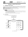
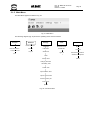
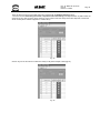
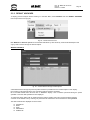
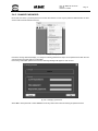
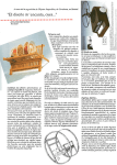
1
AP BLOT
AUTOMATED BLOT PROCESSOR
USER MANUAL
This manual contains DAS reserved information. All rights reserved. Unauthorized copying of this manual or
parts of it is prohibited.
das
srl
Viale Tivoli Km 18,642 – 00018 Palombara Sabina (Roma) - Italy
Tel. (+39) 0774 66840 – 0774 637070 - Fax 0774 634039
E-m ail: info@dasital y.com - http://www.dasitaly.com
AP BLOT
USER MANUAL
Ed.
Index
Indice
Date
Data
Description
Descrizione
0
Rev. 00
18.03.2008
Issue
0
Rev. 01
04.12.2008
Modify CE conformity
0
Rev. 02
13.07.2009
General revision software version 1.9
0
Rev. 03
16.11.2009
General revision software version 1.12
Doc. N° MDU-AP-26-00-02
Rev.03
Date: 16.11.2009
Pag. 3
Execution
Elaborazione
Verification
Verifica
Approval
Approvazione
De Benedictis
A.
Rossi M.
Rossi M.
AP BLOT
USER MANUAL
Doc. N° MDU-AP-26-00-02
Rev.03
Date:16.11.2009
Pag. 5
INDEX
SECTION 1 INTRODUCTION ........................................................................................................................................ 7
1.1.
1.2.
DESCRIPTION ................................................................................................................................................ 7
WARRANTY .................................................................................................................................................... 7
1.2.1.
Requesting service......................................................................................................................................................7
1.2.2.
Ordering spare parts..................................................................................................................................................7
1.3.
CE CONFORMITY CERTIFICATE .................................................................................................................. 8
SECTION 2 - GENERAL SAFETY................................................................................................................................. 9
2.1.
2.2.
2.3.
GENERAL SAFETY WARNING SYMBOLS .................................................................................................... 9
INSTRUMENT WORKING CONDITIONS........................................................................................................ 9
INTENDED USE OF THE INSTRUMENT........................................................................................................ 9
SECTION 3 - GENERAL INFORMATION ................................................................................................................... 11
3.1.
3.2.
3.3.
INSTRUMENT DESCRIPTION: PURPOSE AND FEATURES ...................................................................... 11
MAIN FEATURES .......................................................................................................................................... 11
TECHNICAL SPECIFICATIONS.................................................................................................................... 11
SECTION 4 - INSTALLATION AND START-UP ......................................................................................................... 13
4.1.
4.2.
4.3.
4.4.
4.5.
4.6.
4.7.
UNPACKING.................................................................................................................................................. 13
POSITIONING THE INSTRUMENT............................................................................................................... 15
POWER CONNECTION ................................................................................................................................ 15
INSTALLING WASH AND WASTE CONTAINERS........................................................................................ 15
WORK AREA ................................................................................................................................................. 16
PC CONNECTION ......................................................................................................................................... 16
INSTALLING APEX SOFTWARE ON PC ...................................................................................................... 17
4.7.1.
Minimum PC requirements ......................................................................................................................................17
4.7.2.
Installing APEX software .........................................................................................................................................17
4.7.3.
Installing XCALIB software .....................................................................................................................................17
4.7.4.
Installing USB driver ...............................................................................................................................................18
4.7.4.1.
Windows XP .....................................................................................................................................................18
4.7.4.2.
Windows 2000 ..................................................................................................................................................19
4.7.5.
Installing camera uEye 3.20 driver ..........................................................................................................................22
SECTION 5 – INSTRUCTIONS FOR USE................................................................................................................... 25
5.1.
GENERAL INDICATIONS.............................................................................................................................. 25
5.1.1.
Introduction..............................................................................................................................................................25
5.1.2.
Turning instrument on..............................................................................................................................................26
5.1.3.
Running APEX programme ......................................................................................................................................26
5.1.4.
LICENCES ...............................................................................................................................................................26
5.1.4.1.
Installing licences.............................................................................................................................................26
5.1.5.
Main Menu ...............................................................................................................................................................30
5.2.
SESSION MENU ........................................................................................................................................... 32
5.2.1.
NEW SESSION .........................................................................................................................................................32
5.2.2.
Work Area Display...................................................................................................................................................49
5.2.2.1.
Running a session.............................................................................................................................................55
5.2.2.2.
Displaying Session Results ...............................................................................................................................57
5.2.3.
RUN LAST SESSION................................................................................................................................................59
5.2.4.
LOAD FROM HOST ................................................................................................................................................59
5.2.5.
EXIT .........................................................................................................................................................................59
5.3.
MENU DATABASE ........................................................................................................................................ 60
5.3.1.
ASSAY ......................................................................................................................................................................60
5.3.2.
LAYOUTS.................................................................................................................................................................60
5.3.2.1.
New layout/Set-up ............................................................................................................................................61
5.3.2.2.
Changing Layouts ............................................................................................................................................62
5.3.2.3.
Deleting a set-up/layout ...................................................................................................................................62
5.3.2.4.
Cloning a layout ...............................................................................................................................................63
5.3.2.5.
Renaming layouts .............................................................................................................................................63
5.3.2.1
Configuration protection......................................................................................................................................64
5.3.2.2
Report Print Out...................................................................................................................................................65
5.3.2.6.
Importing layouts .............................................................................................................................................65
5.3.2.7.
Exporting layouts .............................................................................................................................................65
5.3.3.
RESULT ARCHIVES ................................................................................................................................................66
5.4.
MENU SETTINGS ......................................................................................................................................... 68
5.4.1.
LANGUAGE.............................................................................................................................................................68
5.4.2.
INSTRUMENT..........................................................................................................................................................68
5.4.3.
USERS......................................................................................................................................................................69
5.4.3.1.
NEW USER.......................................................................................................................................................70
5.4.3.2.
MODIFY...........................................................................................................................................................71
AP BLOT
USER MANUAL
Doc. N° MDU-AP-26-00-02
Rev.03
Date:16.11.2009
Pag. 6
5.4.3.3.
DELETE ...........................................................................................................................................................71
5.4.3.4.
CHANGE PASSWORD.....................................................................................................................................71
5.4.4.
CHANGE USER .......................................................................................................................................................72
5.4.5.
CHANGE PASSWORD ............................................................................................................................................73
5.5.
LABORATORY DATA .................................................................................................................................... 74
5.5.1.
DOCTOR DATA.......................................................................................................................................................75
5.5.2.
IMPORT SESSION DATA ........................................................................................................................................76
5.5.3.
EXPORT SESSIONS DATA......................................................................................................................................76
5.5.4.
SETTING COMMUNICATION PORT .....................................................................................................................77
5.5.5.
COVER BLOCK .......................................................................................................................................................78
5.5.6.
OPTIONS .................................................................................................................................................................79
5.6.
TOOLS MENU ............................................................................................................................................... 87
5.6.1.
MOVEMENT TESTS ................................................................................................................................................87
5.6.2.
PRIME TEST............................................................................................................................................................88
5.6.3.
LIGHT ON................................................................................................................................................................89
5.7.
MENU ? ......................................................................................................................................................... 90
5.7.1.
Guide........................................................................................................................................................................90
5.7.2.
LICENSES................................................................................................................................................................90
5.7.3.
INSTRUMENT INFORMATION ..............................................................................................................................92
5.7.4.
SOFTWARE COMPONENTS...................................................................................................................................93
5.7.5.
ABOUT.....................................................................................................................................................................94
SECTION 6 – SPECIALIST ACCESS ......................................................................................................................... 95
6.1.
6.2.
6.3.
6.4.
6.5.
6.6.
SPECIALIST and ADVANCED SPECIALIST................................................................................................. 95
SETTING UP A NEW ASSAY........................................................................................................................ 95
6.2.1.
Phases Settings.........................................................................................................................................................98
6.2.2.
Changing an Assay.................................................................................................................................................105
Copying an existing assay ........................................................................................................................... 106
Printing out an assay ................................................................................................................................... 106
Importing a protocol ..................................................................................................................................... 106
Exporting an assay ...................................................................................................................................... 108
SECTION 7 – MAINTENANCE .................................................................................................................................. 109
7.1.
MAINTENANCE CHECKS & PRECAUTIONS............................................................................................. 109
7.1.1.
Cleaning .................................................................................................................................................................109
7.1.2.
Instrument testing...................................................................................................................................................109
7.1.3.
Inspections and checks ...........................................................................................................................................109
7.2.
REPAIRS ..................................................................................................................................................... 110
SECTION 8 - PACKING, TRANSPORTATION, STORAGE AND PUTTING INSTRUMENT “OUT OF SERVICE” . 111
8.1.
8.2.
8.3.
8.4.
8.5.
8.6.
GENERAL INFORMATION.......................................................................................................................... 111
PUTTING INSTRUMENT “OUT OF SERVICE”/DECOMMISSIONING ....................................................... 111
8.2.1.
Temporary Storage.................................................................................................................................................111
PACKING THE INSTRUMENT .................................................................................................................... 111
TRANSPORTATION .................................................................................................................................... 112
STORING THE INSTRUMENT .................................................................................................................... 112
DISPOSAL PROCEDURES......................................................................................................................... 112
SECTION 9 – APPENDIX .......................................................................................................................................... 113
APPENDIX A.............................................................................................................................................................. 113
A.1.
INSTRUMENT DECONTAMINATION ......................................................................................................... 113
A.1.1.
DECONTAMINATION PROCEDURE...................................................................................................................113
APPENDIX B.............................................................................................................................................................. 115
AP BLOT
USER MANUAL
Doc. N° MDU-AP-26-00-02
Rev.03
Date:16.11.2009
Pag. 7
SECTION 1 INTRODUCTION
1.1. DESCRIPTION
This manual provides Users with all the necessary instructions and maintenance recommendations for a safe
and suitable use of the instrument.
Manual content:
− Section 1 - warranty information, Technical Service and the CE conformity declaration
− section 2 - general safety-warnings
− section 3 - general information, instrument performance and technical data
− section 4 - installation and start up
− section 5 - operating instructions for IFA process
− section 6 - instructions for IFA specialist
− section 7 – instructions for regular maintenance by User(s)
− section 8 - how to put instrument out of service, packaging, transport, storage and decommissioning
− section 9 - appendices
This manual is considered an integral part of the instrument; it should always be available for
User/Maintenance Technician consultation.
For accurate installation, usage and maintenance please read all the instructions carefully before use.
In particular carefully read Section 1 “GENERAL SAFETY WARNINGS”, describing suitable operating
procedures to avoid risk of harm or damage to instrument and personnel.
In case of problems or instrument breakdown, refer to Authorised Technical Service and Repairs only.
1.2. WARRANTY
Each provided instrument is completely tested, and guaranteed for twelve months from delivery.
The warranty is for all mechanical and electrical parts. It is granted only for a proper installation, use and
maintenance in compliance to the given instructions contained in this manual.
Due to a misuse of the instrument the above mentioned warranty does not include the travel and labour-hour
expenses as well as all the accommodation expenses.
The warranty does not include any responsibility for direct or indirect to people and material damages,
caused by improper use and maintenance of the instrument. All parts that are subject to deterioration,
because of their specific use, are excluded from the warranty.
1.2.1. Requesting service
When REQUESTING TECHNICAL SERVICE please refer to this manual and indicate any data displayed on
instrument identification label (model, registration number and year of manufacture).
Please Note: only qualified Technicians with suitable equipment and original spare parts are entitled to repair
the instrument; ordinary maintenance should be carried out by Users as described in this manual.
1.2.2. Ordering spare parts
Parts that are subject to deterioration or that are defective and need to be replaced have to be requested
with the following information:
−
Customer purchase order number
−
Name/type and/or version of the instrument
−
instrument code number
−
part code number
−
part description
−
requested quantity
−
name and company address for delivery of ordered original spare parts
Replacing parts with ORIGINAL SPARE PARTS guarantees effective and longer lasting instrument life.
AP BLOT
USER MANUAL
Doc. N° MDU-AP-26-00-02
Rev.03
Date:16.11.2009
Pag. 8
1.3. CE CONFORMITY CERTIFICATE
Declaration of conformity in compliance with 98/79/EC
In-Vitro Diagnostic medical devices Directive (IVD)
DAS srl, manufacturer of the Automated Blot Processor “AP-Blot”, In-Vitro Diagnostic Medical Devices risk class,
declares that this instrument complies with the European Directive 98/79/EC (IVD).
The present conformity declaration, as stated in Annex III of the 98/79/EC Directive, is based upon the following
requirements:
•
•
Quality Management System (ISO 9001:2000): Working Procedures and Instructions for
• Design process control;
• Manufacturing process control;
• Tests, Checks and inspections.
System documentation:
• Technical documents;
• Risk analysis;
• User manual;
• Service manual.
The instrument fully conforms to the following EU directives, which include latest modifications and comply with
national regulations and legislation.
-
Directive 2006/95/EC (ex 73/23/CE) regarding low voltage safety and related standards:
EN 61010-1:2001 - Safety Precautions for electrical, measuring, control and laboratory equipment
-
Directive 2004/108/CE (ex 89/336/EC) - directive regarding electromagnetic compatibility and related
standards:
CEI EN 61326-1 (for electrical, measuring, control and laboratory equipment)
EN 55011 (Emission RF)
EN 61000-3-2 (Harmonics)
EN 61000-3-3 (Flickers)
th
Palombara Sabina, October 27 , 2008
Mario Orsini
Managing Director
AP BLOT
USER MANUAL
Doc. N° MDU-AP-26-00-02
Rev.03
Date:16.11.2009
Pag. 9
SECTION 2 - GENERAL SAFETY
2.1. GENERAL SAFETY WARNING SYMBOLS
In this manual the following symbols stand for danger or warnings:
General DANGER symbol. Indicates that not following relative instructions and warnings can
be a serious safety risk.
Indicates ELECTRICAL VOLTAGE, which could cause death upon contact. Covers with this
symbol can only be removed and replaced by qualified people and only after electrical power
disconnection.
Indicates that instrument is used with reagents and other DANGEROUS CHEMICAL
SUBSTANCES, corrosive, irritating or noxious, which could damage health.
Indicates that the instrument handles potentially infectious samples (e.g. body fluids such as
urine) which could cause INFECTION/CONTAMINATION. Always observe the general safety
standard rules for the presence of these biological substances.
Indicates that not following correct instructions could cause damage to the instrument and/or its
proper functioning.
Indicates important information concerning the instrument or a section of the document that is
important to read with particular attention.
2.2. INSTRUMENT WORKING CONDITIONS
The instrument is intended to be used in the following working conditions:
−
as In Vitro Diagnostic (IVD) medical device as specified in the technical data
−
with chemical reagents and accessories supplied and/or declared to be compatible with the
instrument
−
at a specific temperature and humidity level according to the details given in this manual
−
not to be used and powered in a potentially explosive or fire hazardous environment
The instrument should onlybe be used as described in this manual.
Any other use is regarded as improper
2.3. INTENDED USE OF THE INSTRUMENT
The instrument has to be used for the expected purpose and in perfect technical conditions, by qualified
personnel, in working conditions and following maintenance operations described in this manual.
This manual contains instructions for qualified operators.
−
Qualified Users have to ensure that environmental conditions are suitable and that installation, use
and maintenance are correct and in accordance with general safety rules, as well as following those
specific precautions described in this manual.
−
No User is qualified or entitled to repair the instrument.
−
Only Qualified and specifically trained Technicians are entitled to service and repair the
instrument with original spare parts.
Modifications of the instrument are not allowed. The user is liable for any improper
modifications and for the consequences deriving from them.
For extraordinary maintenance, ask for licensed service centers. The maintenance will be carried
out by Specialized Technicians that will be able to repair the instrument using original spare
parts.
AP BLOT
USER MANUAL
Doc. N° MDU-AP-26-00-02
Rev.03
Date:16.11.2009
Pag. 11
SECTION 3 - GENERAL INFORMATION
3.1. INSTRUMENT DESCRIPTION: PURPOSE AND FEATURES
The AP-Blot instrument dispenses, rinses and reads blots on immuno-enzimatic analysis strips.
It can also dispense, incubate and wash organic samples (pre-diluted when required) and specific reagents.
Up to 48 strips can be processed.
3.2. MAIN FEATURES
Aim
Samples
Automatic analysis of Dot-Blot and Western Blot tests, capable of processing up to 10 different
protocols simultaneously
Maximum capacity: 48 samples in 13x100mm tubes.
Programmable Automatic Predilution for each sample directly carried out on trays
Reagents
Modular Tray for controls, conjugates, chromogens, stop solutions, common reagents (e.g.:
sample dilution solutions)
Reaction Areas
6 racks for 8 different positions: 48 strip total capacity
Dispensation
Three axis arm (X, Y, Z1, Z2) with two independent probes, one with liquid level sensor
Washing
Probe washing: external immersion wash in-well; internal wash with Buffer solution.
Strip: shaking plane washing system
Image acquisition
High resolution colour camera
External liquid bottles
A probe washing WASH bottle container, a WASH BUFFER container for blot washing and a
WASTE bottle container.
Each bottle has a level sensor. Each container is inside the instrument
Immuno-enzimatic
management software
PC software is Windows XP and 2000 compatible capable of:
−
Setting up work lists
−
Automatically executing all session phases (dispensation, incubation, washing and
readings)
−
Creating final reports and result archive
3.3. TECHNICAL SPECIFICATIONS
Sample rack
48 sample tubes (Ø 13mm)
Reagent rack
6 x 100ml phials and 8 control positions
Liquid Containers
2 bottles for wash buffer and waste. Both with liquid level sensors
Strip Holders
6 slides (8 strips per slide) to process up to 48 strips on shaking plane
Dispensation Probe Unit
1 dispensation probe and 1 aspiration probe
Strip Washing
Liquid dispensation and aspiration via two instrument probes
Image acquisition
High Resolution Colour Camera (3.3 Megapixels) mounted above Probes
Dispensation
Up to 2500 µl with a 1 µl resolution
Software
Windows 2000 and XP compatible to set up work list, reports and result archive.
Loading work lists and transmit results via Host Computer interface (LIS)
Minimum PC
Requirements
Power Requirements
− 200 MB free hard disk space
− CD-Rom reader
− RAM 512 MB
− Pentium 4
− Standard video card:VGA 1024x768 16 million colours
− Free USB 2.0 port
230/115 VAC, 50-60Hz, 150W
Optional
Bar Code Reader (BCR) for samples with position ID
Measurements (in cms)
79 x 61 x 65 h
Weight
78 Kg
SECTION 4 - INSTALLATION AND START-UP
When installing and setting up the instrument, carefully follow safety warnings and general rules
described in Section 1.
4.1. UNPACKING
The instrument is packed with a wooden box. To unpack the instrument follow the instructions described below:
a)
b)
Remove the 2 plastic covers (1-2) from the instrument right side and the other ones from the left side. Screw in
the 4 handles on both sides (3-4) for manual instrument placement. Once in position remove the handles e put
back in place the plastic covers.
Remove the 4 screws that hold the instrument on to the wood base (5-6)
1
c)
2
3
4
5
6
Remove screw and bracket (7), screw in the same place using the screw removed before
7
Doc. N° MDU-AP-26-00-02
Rev.03
Date:16.11.2009
AP BLOT
USER MANUAL
d)
e)
f)
g)
8
Pag. 14
Remove screws (8,9) and related brackets
Remove the Z block holder (10) as indicated
Remove the protection cap from the camera (11)
Remove the blocking tools (12) from the oscillating plane
9
10
12
11
If the instrument was already in use check for the DECONTAMINATION DECLARATION
(see Appendix A of this manual).
KEEP THE EMPTY BOX! This box is designed and manufactured specifically for this
instrument only and can be used for future transportation.
Doc. N° MDU-AP-26-00-02
Rev.03
Date:16.11.2009
AP BLOT
USER MANUAL
Pag. 15
4.2. POSITIONING THE INSTRUMENT
The instrument has to be placed on a level bench (table or equivalent work surface) and in an
o
o
environment where the temperature ranges between 15 C and 35 C, humidity levels remain under
80% and the instrument is protected from direct sun light.
4.3. POWER CONNECTION
Once the instrument has been placed in position proceed with plugging it into the correct power source 230VAC or
115VAC (see label) using the cables supplied with instrument.
Warning: check that electrical power source corresponds to the source indicated on the label stuck on
the side of the instrument!
Warning: check that fuses correspond to those indicated on the side of the instrument!
o
230 VAC n 2 x 5A fast fuses
o
115 VAC n 2 x 10A fast fuses
4.4. INSTALLING WASH AND WASTE CONTAINERS
Figure 1 shows how wash/waste containers are connected up to the instrument.
T1
T2
T3
fig. 1 - Hydraulic circuit
R
Level sensors connector
T1
Wash: probe wash solution bottle
T2
Buffer: strip wash solution bottle
T3
Waste: waste liquid bottle
PROCEDURE
Before switching on instrument:
− fill T1 and T2 bottles with solution according to method requirements
− connect empty T3 (waste) bottle container
− connect tubing to appropriate containers as indicated in figure 1
− check tubings are correctly connected and in good condition
− plug level sensor lead to instrument socket (connector R)
Note: at the end of a session or before performing maintenance procedures: run wash session for
instrument.
Doc. N° MDU-AP-26-00-02
Rev.03
Date:16.11.2009
AP BLOT
USER MANUAL
Pag. 16
4.5. WORK AREA
Probe
washing
basin
48 position Sample rack
Camera Calibration Area
Control - reagent rack
Bottles
Strip holder trays
fig. 2- AP-Blot Work Area
4.6. PC CONNECTION
The instrument is equipped with a USB port for PC connection. To install the USB driver please see par. 4.7.4.
Plug, fuses, switch
2.0 USB communication
port
fig. 3- Electrical socket/ 2.0 USB port
AP BLOT
USER MANUAL
Doc. N° MDU-AP-26-00-02
Rev.03
Date:16.11.2009
Pag. 17
4.7. INSTALLING APEX SOFTWARE ON PC
4.7.1. Minimum PC requirements
−
−
−
−
−
−
−
Microsoft Windows 2000 or XP
200 MB free hard disk space
CD-Rom reader
512 MB RAM
Pentium 4
Standard video card VGA 1024x768 16 million colours
2.0 USB port
4.7.2. Installing APEX software
Insert “APEX software” CD into computer. APEX software is self-installing. If this automatic installation process does
not begin, it can be launched manually by clicking on setup.exe file which appears on the display.
Choose programme display language (English or Italiano). NB: this choice is only valid for the installation.
Click “Next” until installation procedure window appears:
•
Click on “Complete” to choose default file - C:\Programmes\APEXSuite\APEX;
•
Click on “Personalise” to change default file destination path.
After installing APEX software continue to install USB driver as described later (see para 4.7.4).
At the end of the installation launch APEX software by double clicking on APEX icon which appears on the desktop.
NB: User can access all APEX suite programmes from the “APEX” group from main menu (by selecting Start>all
programmes>APEX Suite).
4.7.3. Installing XCALIB software
NB: XCALIB software is the AP-Blot Service software
Insert “XCALIB software” CD into computer. XCALIB software is self-installing.
If this process does not automatically start then click on the setup.exe file from the CD displayed.
Choose language after installation has begun (English or Italiano). NB: this choice is only for the installation
procedure.
Click on “Next” until installation choice window is displayed:
•
Click on “Complete” to install default file C:\Programmes\APEXSuite\XCALIB;
•
Click on “Personalise” to change installation file path destination.
When software is installed continue by installing USB driver as described later (see para 4.7.4).
At the end of installation procedure, launch XCALIB software by clicking on XCALIB icon which appears on the
desktop as part of the “APEX Suite” group. Or From the main menu programme bar (select “start>all
programmes>APEX Suite)
Doc. N° MDU-AP-26-00-02
Rev.03
Date:16.11.2009
AP BLOT
USER MANUAL
Pag. 18
4.7.4. Installing USB driver
The instrument communicates with PC through a convertor USB port (RS232-USB).
2 driver installation procedures are required: the first to communicate with the electronic part of the instrument and the
second to emulate (=imitate) a standard PC serial port.
When these drivers have been correctly installed a new serial port has been added to the PC (e.g.: COM5).
4.7.4.1. Windows XP
Connect instrument to the PC USB. The “New Hardware Guided Installation” procedure will automatically start up
with the following display:
fig. 4
Select “No, not yet” in answer to question: “Connect to Windows Update to search for new software?” then click on
“Next”
Select “Install from list or specific path” then click on “Next”.
fig. 5
Click “BROWSE” to find file containing USB driver, then click OK and continue.
If Windows XP is configured to warn of the installation of a non-WHQL certified driver a “Warning! Message” will
appear: click on “Continue anyway”.
The Windows programme displays a note at the end of the installation - click on “END” to complete.
The same procedure now automatically begins to install a serial port emulator – follow instructions as above.
Doc. N° MDU-AP-26-00-02
Rev.03
Date:16.11.2009
AP BLOT
USER MANUAL
Pag. 19
When both drivers have been installed, open Control Panel select System then click on Hard Ware file then Hardware
Resources.
The new USB/Serial port should appear as an additional serial port called “USB Serial Port” (see below for example –
called “COM7” in fig. 6).
fig. 6
Now APEX or XCALIB software can be launched and the appropriate communication port can be selected.
4.7.4.2. Windows 2000
Connect instrument to PC USB. The “New Hardware Guided Installation” procedure will automatically start up.
Click on “Next” to continue.
Fig. 7
Doc. N° MDU-AP-26-00-02
Rev.03
Date:16.11.2009
AP BLOT
USER MANUAL
Select “Search for appropriate Driver”
Continue by clicking on “Next”.
fig. 8
Select only “Specify path” and click on “Next”.
fig. 9
Pag. 20
Doc. N° MDU-AP-26-00-02
Rev.03
Date:16.11.2009
AP BLOT
USER MANUAL
Pag. 21
Click on “BROWSE” and specify USB driver path file in display which appears below:
Fig. 10
When file with USB driver has been opened, select FTDIBUS.INF and then click “Next” to continue installation.
A Windows display announces successful installation and the USB is ready.
A similar process begins for the serial port emulator driver. Follow similar procedure.
When both drivers have been installed open Control Panel, select System and then Hardware file and open the
“Hardware Resources”.
The “new” USB/Serial Port should appear as an additional communication port: “USB Serial Port” (e.g.: COM5 as
shown below Fig.12).
Fig. 11
Doc. N° MDU-AP-26-00-02
Rev.03
Date:16.11.2009
AP BLOT
USER MANUAL
Pag. 22
4.7.5. Installing camera uEye 3.20 driver
4.7.5.1. Windows XP
To install uEye 3.20 camera driver proceed as follows:
1)
2)
Disconnect instrument from PC 2.0 USB
From driver CD click on display which appears: “CAMERA DRIVER uEye_3.20” then select file
"uEyeBatchInstall_320.exe".
fig. 12
3)
Select “Install the uEye USB driver” option by typing in ‘2’. Press Enter
fig. 13
4)
When installation is successfully completed a confirmation message will appear: “uEye driver installed
correctly”. To continue press Enter.
fig. 14
Doc. N° MDU-AP-26-00-02
Rev.03
Date:16.11.2009
AP BLOT
USER MANUAL
5)
6)
Now connect APBLOT instrument to the PC 2.0 USB port.
When new hardware is recognised “Connect to Windows Update to search for new software?” appears and
now select “No, not yet” - then click on “Next” to continue.
fig. 15
7)
Pag. 23
Select “Automatic software installation” and click “Next”.
fig. 16
Doc. N° MDU-AP-26-00-02
Rev.03
Date:16.11.2009
AP BLOT
USER MANUAL
8)
If a display shows incompatibility with Windows XP click on “Continue” and installation continues:
fig. 17
9)
The following display will appear when installation has been successful:
fig. 18
10) Click on End
11) NB: sometimes camera driver installation software requests procedure to be repeated from point (6)
12) Now launch APEX or XCALIB software and choose appropriate communication port.
Pag. 24
AP BLOT
USER MANUAL
Doc. N° MDU-AP-26-00-02
Rev.03
Date:16.11.2009
Pag. 25
SECTION 5 – INSTRUCTIONS FOR USE
5.1. GENERAL INDICATIONS
The instrument is used with chemical reagents and other DANGEROUS CHEMICAL SUBSTANCES
(corrosive, irritant and harmful) which can damage health. When this label is present particular care and
attention must be taken to follow all manufacturer recommendations.
The instrument handles potentially infected samples (urine and human serum etc.) therefore INFECTIONS or
CONTAMINATION might occur.
Take all proper precautions in the presence of such biological substances.
Use protective clothing, gloves and goggles.
IIn particular:
−
Wear protective clothing, goggles and gloves
−
At the end of a work session, check condition and carefully clean work panel and accessories with a cloth
soaked in a 0.5% sodium hypochlorite solution
−
Any waste material produced during the sessions and cleaning process can be dangerous – with potential
risk of contamination for personnel and other matter.
−
Dispose of such waste material in accordance with local laws and regulations
5.1.1. Introduction
The following table shows the main way this instrument functions.
Run Program
WORK SESSION
OTHER FUNCTIONS
Run work session or
other function?
Database
New session
Settings
Run last session
Tools
Load from Host
?
fig. 19– General functions
Doc. N° MDU-AP-26-00-02
Rev.03
Date:16.11.2009
AP BLOT
USER MANUAL
Pag. 26
5.1.2. Turning instrument on
Press the on/off button on the right hand side of instrument. There are three lights on the front of the machine:
POWER
Green light
Indicates that the instrument is switched ON
RUN
Yellow light
ALARM
Red light
Indicates a programme is running
This shows that at least one liquid error has been found: the tip has not found any
liquid in one of the containers (sample tube or reagent container) on the work area
(Note 1)
Please note: The position where the liquid error has been found will be displayed on the PC screen.
5.1.3. Running APEX programme
The Apex programme icon appears on the desktop. Double click on it to launch programme.
Apex
Fig. 20 – Programme icon
5.1.4. LICENCES
5.1.4.1.
Installing licences
Double click on programme icon to begin English language programme – the following window display appears asking
if any new licenses are to be loaded (Fig. 29 below):
Fig. 21 – License request
Click No to exit this part of the programme
Click Yes to display Licenses window which lists possible licenses to be loaded as shown below Fig.22
fig. 22- Licenses Window
Please note: The license is only valid for one instrument.
Please note: Loading a Demo License for this specific instrument overwrites any other licenses.
Any other licenses present (if required) should be re-loaded.
Doc. N° MDU-AP-26-00-02
Rev.03
Date:16.11.2009
AP BLOT
USER MANUAL
Pag. 27
Select Load new license to open display and CD installation folder and then click “Licenses”.
These are contained in an *.xml file and can be opened by selecting Apri (Fig. 23) or by clicking Demo mode and
selecting type of instrument to function in Demo Mode – without being connected to a PC.
Choose License for instrument and click “Apri/Open”:
Fig. 23– Selecting the license
fig. 24
Click Deselect all to de-select license and not load it.
Click OK to load license.
Doc. N° MDU-AP-26-00-02
Rev.03
Date:16.11.2009
AP BLOT
USER MANUAL
Pag. 28
Select OK to show license in the licenses window as shown below in Fig. 33
fig. 25
When Licenses window is closed (exit) the following form will be displayed automatically.
Insert both login and password and select Enter.
Fig. 26- Software access form
After inserting login and password the Communication port settings window will open to input communication port
setting from set of pull-down lists Fig. 26
Fig. 27 - Port settings
Select Set to store selected communication port. This selection is confirmed as shown below Fig. 27
Select Cancel to exit this part of programme and leave original setting.
AP BLOT
USER MANUAL
Doc. N° MDU-AP-26-00-02
Rev.03
Date:16.11.2009
Pag. 29
Click OK. The Main Menu will appear if the selected port is correct and the instrument is on.
Fig. 28– Confirmation window
A Warning message will appear (Fig. 28) asking if communication port should be changed. If selection is incorrect, or
if Port is correct, but the instrument is not turned on.
Fig. 29– Change selected port request
If the instrument is turned off, turn it on and select No.
The Main Menu will now appear. Click on “light” icon
(fig. 30) if the port is correct the light will come on.
fig. 30- Main Menu On/Off light
If instrument is on but the light does not flash ‘on’ this indicates that software is only in DEMO mode.
Change port selection.
The light will turn on as soon as the correct port is selected.
Click on Light Icon to turn light off.
Doc. N° MDU-AP-26-00-02
Rev.03
Date:16.11.2009
AP BLOT
USER MANUAL
Pag. 30
5.1.5. Main Menu
The Main Menu appears as below in Fig. 39:
Fig. 31 -Main Menu
The following diagram (Fig. 32) shows the operating menu and how it works:
Session
Database
Settings
Tools
?
Result archives
Language
Movement tests
Guide
Run last session
Assays
Instrument
Prime Test
Load from host
Layout
New session
Work area
Exit
Light on
Licenses
Instrument information
Users
Software Component
Change User
About
Change password
Laboratory data
Doctor data
Import session data
Export session data
Communication port
Cover block
Option
Fig. 32– Functions Menu
Doc. N° MDU-AP-26-00-02
Rev.03
Date:16.11.2009
AP BLOT
USER MANUAL
Pag. 31
Menu Functions
Menu:
Description:
Session
New Session
To set up new work session
Run last session
Runs last session with previous settings
Load from host
Import of work list from Host Computer
Exit
Leaves programme
Database
Result archives
Display results of all stored sessions and results for all patients examined in each
session
Assay
Manages all functions concerning assays
Layout
This layout display manages all Strip functions set-ups.
Settings
Language
Sets up display language for menus, windows etc
Instrument
To choose one or more instruments
Work area
Shows the work area of the selected instrument
Users
To insert/change/delete User password for programme.
Change User
To change any software User access.
Change password
To change password of current User
Laboratory data
To input information about laboratories where sessions take place.
Doctor data
To input information about Doctor responsible for sessions.
Import session data
To import session in *.mdb file format and overwrite stored sessions.
Export session data
To export sessions in *.mdb file format and store sessions in archive.
Communication port
To set up serial port to connect AP-BLOT instrument to PC.
Cover lock
Sets safety block levels for cover
Options
Access to different functions, about each or all instruments: error trace type, session
set up forms, time storage algorithm, etc…
Tools
Movement tests
Tests movements of: different Axes, shaking plane, primes hydraulic circuit, Optical
sensor test
Prime test
Hydraulic circuit prime test from selected prime source
Light on
Testing light
?
Guide
Displays User Manual in chosen language
Licenses
Display/load/deletes instrument licences
Instrument information
Displays serial number, code, card types and firmware version of connected and
working instrument
Software components
Displays information about different APEX software components.
About
Information about APEX software
Doc. N° MDU-AP-26-00-02
Rev.03
Date:16.11.2009
AP BLOT
USER MANUAL
Pag. 32
5.2. SESSION MENU
5.2.1. NEW SESSION
Click on Session from the Main Menu and select New Session (Fig 33) to begin setting up new work session
from a new display. This Last Session display shows the last settings set-up on work area – please note – this
last session has not necessarily been run, but has been at least set-up on Lay-Out display.
There are two steps to set up a work session: the first concerns choosing one or more assays to be executed
by one or more instruments.
The second step is associating one or more samples to one or more assays. A Session can be more easily
identified by filling in the Session Name field.
fig. 33
The Session Settings display opens where one or more patients can be associated to one or more assays (Fig.2).
fig. 34
Doc. N° MDU-AP-26-00-02
Rev.03
Date:16.11.2009
AP BLOT
USER MANUAL
In the “Work list” section click
Pag. 33
icon to add an assay to the work list (Fig.34).
fig. 35
This opens the “Assay selection” display where Assays required can be selected (Fig.4) and added to work list after
clicking “Confirm”.
Repeat this procedure if more than one assay is required for the work list.
fig. 36
Please Note: If more than one instrument is connected to the same PC, the instrument specifically required for the
Assay can be selected from the “Instrument” pulldown listing in the “Instruments” section of the “Assay selection”
display.
Doc. N° MDU-AP-26-00-02
Rev.03
Date:16.11.2009
AP BLOT
USER MANUAL
Pag. 34
The different sections:
- “General info” : shows the general information about the Assay (Name, short name etc)
- “Repetitions” : shows how many repeats are set-up for both samples and controls (where 1= corresponds to a
single sample/control dispensation)
- “Controls” : shows information about Controls dispensation – which takes place either before or after the samples.
The “Repetition” and “Controls” sections have default settings specifically for Dot Blot Assays and consequently
cannot be changed.
Click Confirm on Assay Selection display and the Assay is added to the Work List and displayed on the Session
Settings with the short name shown in the first column of the table (Fig.37).
fig. 37
Patient (Sample) Codes can also be added to the Work List in the “Sample code” column.
These codes can be inserted either one by one, or in groups (using “multiple selection” option).
to Insert Single Code (Fig.38): type in code (point a) in the Sample Code column, then press Enter.
The cursor flashes in cell below waiting for a new code to be typed in.
A Patient Card icon appears on the left (point b) and a small box appears on the right (point c) to input sample/assay
association.
fig. 38
Doc. N° MDU-AP-26-00-02
Rev.03
Date:16.11.2009
AP BLOT
USER MANUAL
Pag. 35
Multiple Patient Code Selection method (Fig.39): to insert a group of Patient Codes click on “Sample code”
heading (point a) to open Multiple insert window (point b).
Type in “Patient name” prefix code and also the “Patient number” which corresponds to how many Patient Codes
should be generated at the same time.
fig. 39
Doc. N° MDU-AP-26-00-02
Rev.03
Date:16.11.2009
AP BLOT
USER MANUAL
Pag. 36
For instance: Type “P” as the prefix code in “Patient name” text box and then type in the number ‘5’ in the “Patient
number” box and click “OK” (Fig.40).
fig. 40
In this case - 5 Patient numbers are automatically generated starting with “P” followed by an increasing number
starting from 1 (P1, P2… etc see Fig.41).
fig. 41
This work list now displays both samples and assays.
Now define a state for each Assay request to complete this session setting.
The possibilities are:
Not processed: represented by
To be processed: represented by
Suspended: represented by
Validated: represented by
Running: represented by
icon
icon
icon
icon
icon
Doc. N° MDU-AP-26-00-02
Rev.03
Date:16.11.2009
AP BLOT
USER MANUAL
Pag. 37
Click to check each box that corresponds to associating the assay with that patient sample as shown in Fig.42. A
yellow check confirms the request to process this sample/assay association which is then inserted in the work list to
be processed.
fig. 42
Click again on
icon to add another Assay (Fig.43) if required; this icon moves to the right when a new assay
is included and short name displayed in a column.
fig. 43
Doc. N° MDU-AP-26-00-02
Rev.03
Date:16.11.2009
AP BLOT
USER MANUAL
Pag. 38
There are also two ways to associate assays and samples with the Multiple Selection option:
- The first concerns associating more than one patient to the same Assay (a multiple selection of patient codes as
shown in Fig.44): click on (down) arrow at the top of the column under the Assay Short name required, to select the
whole column (when selected it appears in a darker blue).
fig. 44
Click on any box in this column to select this Assay for all patient sample codes (Fig.45).
fig. 45
Doc. N° MDU-AP-26-00-02
Rev.03
Date:16.11.2009
AP BLOT
USER MANUAL
Pag. 39
Please note: this selection can easily be modified by simply ‘de-clicking’ the box corresponding to the patient code to
be excluded from this Assay
(Fig.46).
fig. 46
- The second Multiple Selection method concerns associating more Assays to the same patient: by clicking on the
arrow on the right of the Patient (Sample) Code the whole Row can be selected (Fig.47).
fig. 47
Doc. N° MDU-AP-26-00-02
Rev.03
Date:16.11.2009
AP BLOT
USER MANUAL
Pag. 40
At this point (when row is selected it appears in a darker blue) click on any box to extend the selection to the entire
row (Fig.48).
fig. 48
The Top Section of the Session Settings display (under main menu toolbar) shows the total and partial request
counters (Fig.49).
The “Global info” section shows the overall information about the Session setting.
Under “Sample” - the “Associated” and “Not associated” figures refer to how many samples have been associated
and how many have not been associated to at least one Assay.
The “Request” section shows how many samples have been requested for processing, or how many have been
suspended, compared to the total number of requests present for this session (which corresond to the yellow checks
in the boxes).
Click on Assay Short name from Work List to display any information about the “Assay” section:
“General info” shows the general information about an Assay (type, etc)
“Request” shows how many Assays have been requested for processing (
) and those which have been
); this is why an Assay counter can be ‘partial’.
suspended (
“Repetition” shows how many repetitions are requested for samples and controls.
fig. 49
In the Assay section (Fig.49) click on ‘Previous’ arrow
Assays which have been loaded for the session.
and ‘Next’ arrow
to display information about other
Doc. N° MDU-AP-26-00-02
Rev.03
Date:16.11.2009
AP BLOT
USER MANUAL
Click
Pag. 41
icon to display the Assay selection window (Fig.50) where the default settings of the Assays are shown.
fig. 50
Doc. N° MDU-AP-26-00-02
Rev.03
Date:16.11.2009
AP BLOT
USER MANUAL
Pag. 42
The order of Patient (Sample) Codes from the work list, which are then displayed on the sample rack, can be
changed. For instance if the work list appears as shown in Fig. 51 after confirming the Work Area lay-out the sample
rack is displayed as shown in Fig.52.
fig. 51
fig. 52
Use the two arrows along the right side of the Session Settings display: select a Patient Sample Code and then click
to move selection up or click
to move selection down.
For instance Fig. 53 shows that the first row (which corresponds to “Paziente 1” code) has been selected followed by
a click on the Move Down arrow (Fig.53) .
fig. 53
This moves the “Paziente 1” sample code down one row – or into second position as shown in Fig.54.
Click Validate and the Sample Rack display from the Work Area also displays this change (Fig.55).
fig. 54
fig. 55
Doc. N° MDU-AP-26-00-02
Rev.03
Date:16.11.2009
AP BLOT
USER MANUAL
Pag. 43
By selecting Paziente 1 code row again and clicking the Move up arrow (Fig.56) this returns Patient sample code to
previous position.
fig. 56
If required any assay can also be suspended from this current work session after the Patient sample code has been
inserted and processed in a different session. First select Patient sample code row by clicking on arrow and then on
the Suspend option as shown in Fig.57.
fig. 57
Doc. N° MDU-AP-26-00-02
Rev.03
Date:16.11.2009
AP BLOT
USER MANUAL
Pag. 44
This example shows that both Sample Assay requests for the same Patient sample code have been suspended
(Fig.58).
fig. 58
If a work session is now run then only those requested (with a yellow check) would be processed.
The next session work list would only display the one “Paziente 1” patient sample code associated with the A1 and A2
Assays and showing their suspended state (Fig.59).
fig. 59
Doc. N° MDU-AP-26-00-02
Rev.03
Date:16.11.2009
AP BLOT
USER MANUAL
Pag. 45
A sample or Assay can also be removed from the work list by selecting the corresponding row/column and then
clicking on the Remove option (Fig.60).
fig. 60
Cancelling a Patient sample can only take place after this procedure has been confirmed.
Doc. N° MDU-AP-26-00-02
Rev.03
Date:16.11.2009
AP BLOT
USER MANUAL
Pag. 46
Click “Validate” to confirm Assay selections and associations. The yellow checks become green indicating that they
have been ‘validated’ (Fig.61).
If any request is not confirmed a Warning Message appears.
Read only or Full session options are now possible from this ‘validated’ Session Setting display.
fig. 61
Lastly, information about a patient sample code can be included in the corresponding Patient Card: click on
on the left of Patient (Sample) Code to display a new window (Fig.62).
The Patient-ID code is already displayed automatically (corresponding to that on the Work List) and further
information about the patient can be compiled in the other fields. Click Confirm to store information.
fig. 62
icon
Doc. N° MDU-AP-26-00-02
Rev.03
Date:16.11.2009
AP BLOT
USER MANUAL
Pag. 47
The following fields are obligatory: Patient-ID, name, surname (family or last name) and date of birth (Fig.63). This
Patient Card can be also compiled during the running phase as the Session setting can be opened at any time and
information is only stored at the end of the session. When Patient Cards have been stored they can be displayed in a
list and included again for another session by clicking on
icon(Fig. 64).
Click
icon to delete card and consequently any information which might be incorrect.
fig. 63
fig. 64
This current session setting display can be used to set-up a new work session while the software is running another
session.
Doc. N° MDU-AP-26-00-02
Rev.03
Date:16.11.2009
AP BLOT
USER MANUAL
Pag. 48
For example: by clicking on
option while a session is running opens the Session Settings display
which shows all the sessions requested in RED (because they can no longer be changed as they are being processed
Fig.65).
New requests of sample codes associated to assays can be added now to be processed later (for instance in Fig. 65
‘Nuovo Paziente’ is an example of a New Patient).
fig. 65
Doc. N° MDU-AP-26-00-02
Rev.03
Date:16.11.2009
AP BLOT
USER MANUAL
Pag. 49
5.2.2. Work Area Display
When setting up the work session is completed the Work Area display can be accessed (Fig. 28)
There is a total of nine racks present on the work area:
n°1 Probe Washing basin
n°2 Reagent Racks
n°1 Sample Rack
n°6 Strip plates
Fig. 66 – Work area
Probe Washing Basin
The Probe Washing Basin is on the top left of the work area layout display.
Double click on it to display condition as shown here:
Fig. 67 – Probe washing basin
Click on Report to display a print preview of all the information contained in the Printed Report.
Click on the images of each single rack to open a display of selected rack and a list of information about each rack
phial. Different windows now show different racks.
AP BLOT
USER MANUAL
Doc. N° MDU-AP-26-00-02
Rev.03
Date:16.11.2009
Pag. 50
SAMPLE RACK
Fig. 68 – Sample rack
The Sample Rack is composed of 48 different interactive positions.
Click on any position to display all the information about that particular position.
The colour of each sample position shows whether a sample is present. Red = present; Grey a sample is not present.
The information along the bottom of the window:
SAMPLE POSITION
TYPE
ID
REQUIRED VOLUME
Click on Report at the bottom of the window to display a print preview of all the information that can be printed out.
AP BLOT
USER MANUAL
Doc. N° MDU-AP-26-00-02
Rev.03
Date:16.11.2009
Pag. 51
REAGENT RACK
Fig. 69 – Standard Reagent rack with controls
fig. 70– Additional reagent rack
There are two racks, one for reagents with positions: numbered R1 through to R9, and a control rack with positions
C1 to C8 and there is a CL position for a Cleaning solution.
These positions are interactive and show different colours depending on the Session assays.
The example of the assay session is composed of the following flacons:
PRE-TREATMENT (R2)
SAMPLES AND CONTROLS (R1 and C1)
CONJUGATE (R7)
SUBSTRATE (R8)
ADDED PHASE 1 (R3)
ADDED PHASE 2 (R4)
ADDED PHASE 3 (R5)
ADDED PHASE 4 (R6)
STOP SOLUTION (R9)
Doc. N° MDU-AP-26-00-02
Rev.03
Date:16.11.2009
AP BLOT
USER MANUAL
Pag. 52
The positions for the washing solution is also shown (CL).
Eight other positions show the controls.
The colour indicates whether the control is present: green = present; grey is not present.
Click on any position in the table or representation on the display, to show all the information regarding that container
The information displayed on the left of the window:
POSITION
TYPE
ID
REQUIRED VOLUME
ASSAY
Click on Report at the bottom of the window to display a print preview of all the information that can then be printed
out.
STRIP PLATE
Fig. 71 – Strip Plate
There are 8 strips for each strip plate.
Information about any of the eight strips on the strip plate can be displayed simply by clicking on the selected strip.
Different colours represent either sample or control strips:
green represents a control strip, red represents a sample strip.
Information about any specific strip or position can also be displayed by clicking on the strip position (in the Data
section under the Position listing).
The information displayed along the bottom of the window are:
POSITION
TYPE
IDENTIFIER
REQUIRED VOLUME
ASSAY
Different strips can be used in all six strip plates to execute different tests at the same time, although all the strip
plates are structurally the same.
Click on Report at the bottom of the window to display a print preview of all the information that can then be printed
out.
Along the bottom of the Work Area display: the Next option opens the next page and the Previous option opens the
previous page.
Kit Data, Report and Info Buffer are explained as follows:
Doc. N° MDU-AP-26-00-02
Rev.03
Date:16.11.2009
AP BLOT
USER MANUAL
Pag. 53
KIT DATA
Select Kit Data option to display a window to input information about each assay kit fig 72.
Fig. 72 – Kit Data
Kit Information can be referred to one or more assays and they can be numbered. Each kit information can
include: ID number, Lot number, Producer, Expiry Date.
Cancel option closes this window without any additional information and Save stores all data which will also be
displayed with the results (fig. 73).
fig. 73– Results Information
Doc. N° MDU-AP-26-00-02
Rev.03
Date:16.11.2009
AP BLOT
USER MANUAL
Pag. 54
BUFFER INFO
Click Buffer Info along the bottom of the Work Area display to display the Buffer Report showing which Buffer has
been used to wash strips (fig. 74):
fig. 74– Buffer Info Report
REPORT
Click on Report along the bottom of the Work Area display to show a print preview with the following information
about slides and racks:
RACK POSITION
TYPE
ID
REQUIRED VOLUME
ASSAY
fig. 75– Report
AP BLOT
USER MANUAL
Doc. N° MDU-AP-26-00-02
Rev.03
Date:16.11.2009
Pag. 55
5.2.2.1. Running a session
Click Next option on Work Area window (Fig. 66) to open Running Session window (Fig. 76).
The analysis sessions start here and results are displayed at the end of each session.
Fig. 76 – Running session
The assays used in the analysis session are listed at the top of the window. For each assay a timeline shows the
progress throughout the work phase. The right side of the screen shows the assay name, the current phase of the
assay, and the remaining time in hours-minutes-seconds.
The horizontal bar in the centre of the screen shows the percentage or rate of progress of each given session.
Directly underneath this bar four sections show: first any information about the Current Session, followed by second
section to display any Errors that might occur during the session, the third shows information about Thermal
Regulation, fourth shows the Session Time – how long before it finishes or: if completed it shows when it started and
finished.
The Unblock lid option is to open the shield cover during a session if the safety level is high.
The Clean list option empties the errors list present. All errors are still printed out in the final report.
Select Start to run analysis session.
The Pause key can temporarily put the session on hold. To restart click on Start.
Any analysis session can be definitively abandoned by selecting the Stop button.
The Back option displays previous window, even during session.
The Exit option closes run session phase. It is not active during the session.
Doc. N° MDU-AP-26-00-02
Rev.03
Date:16.11.2009
AP BLOT
USER MANUAL
Pag. 56
ASSAY INFO
Click on Assay name (Fig.77) to display information about set-ups as shown here:
Fig. 77 – Assay Info
List of PHASE COLOURS
icon (Fig. 76) to display which phase of the assay they represent (Fig. 78).
Each Phase has a colour. Click on
This list only display phases that correspond to current session.
Fig. 78 – List for phase colors
AP BLOT
USER MANUAL
Doc. N° MDU-AP-26-00-02
Rev.03
Date:16.11.2009
5.2.2.2. Displaying Session Results
At the end of each session the results are automatically shown for immediate consultation. (Fig. 79).
Fig. 79- Results window
Select Cancel to close Results window without displaying results.
The Error button shows the following window in case the lid is opened during the reading:
Pag. 57
AP BLOT
USER MANUAL
Doc. N° MDU-AP-26-00-02
Rev.03
Date:16.11.2009
Pag. 58
Select Detail to open display with results for each analysed strip as shown here:
fig. 80– Details of Strip Results
Click icon
to show print preview and further Detail for each strip (Fig. 81).
fig. 81– Display Details
In this display the fields concerning interpretation of results and additional notes (coloured Orange) can be changed
before results are stored.
Click Save icon
to save any changes – and Print preview displays how results can be printed and
icon directly proceeds to print out results.
Print
Doc. N° MDU-AP-26-00-02
Rev.03
Date:16.11.2009
AP BLOT
MANUALE D’ USO
Pag. 59
5.2.3. RUN LAST SESSION
The last run session can be run again from Main Menu, select Session and then Run last session from pull down list
Fig. 82– Run last session
This directly opens the Run Session display.
5.2.4. LOAD FROM HOST
This function concerns importing from Host and/or BCR (Fig. 83).
fig. 83
5.2.5. EXIT
From Session pull down menu select Exit to leave the programme.
If a session is running then a confirmation window appears first.
Fig. 84 – Exit
AP BLOT
MANUALE D’ USO
Doc. N° MDU-AP-26-00-02
Rev.03
Date:16.11.2009
Pag. 60
5.3. MENU DATABASE
5.3.1. ASSAY
See Paragraphs 6.2.
5.3.2. LAYOUTS
This display shows the different possible strip set-ups associated with different types of assays and is in two sections.
(Fig. 55): The first (top) section Assay Type is for selecting Assays from a pull down listing. The selection shown here
is Dot Blot. The second section (Layouts) displays a list of possible default set-ups associated with the Dot Blot assay
and a series of options to access different functions for set-up (like for the assays).
Double click on any part of listing to display details of this set-up layout in a separate window and where the name of
the Antigen can also be changed (Fig. 86).
fig. 85– Layout/Set-up
AP BLOT
MANUALE D’ USO
Doc. N° MDU-AP-26-00-02
Rev.03
Date:16.11.2009
Pag. 61
fig. 86 – Details of set-ups
5.3.2.1.
New layout/Set-up
Click on New option in Layout display to create a new Strip set-up and select a number of antigens from the list
displayed to coincide with the number of layouts (e.g.: AD-L01 has one antigen).
fig. 87– New set-up/layout
AP BLOT
MANUALE D’ USO
5.3.2.2.
Doc. N° MDU-AP-26-00-02
Rev.03
Date:16.11.2009
Pag. 62
Changing Layouts
Click Change to change antigen name and controls, by clicking on Chemical Data tab, filling in Antigen field, display
preview layout and possible print out by selecting Report.
fig. 88– Changing layout/set-up
5.3.2.3.
Deleting a set-up/layout
Click on a layout from listing Fig. 85 and then select Delete option to delete this layout.
AP-Blot
USER MANUAL
5.3.2.4.
Doc. N° MDU-AP-26-00-02
Rev.03
Date:16.11.2009
Pag. 63
Cloning a layout
Click on a layout from listing Fig.90 and then select Clone option to copy this layout which is automatically renamed
NewLayout1 as seen here:
fig. 89 – Cloning layout
5.3.2.5.
Renaming layouts
Click on a layout from listing (Fig.89) and then select Rename and then name can be changed directly on the listing.
fig. 90– Renaming layouts
AP-Blot
USER MANUAL
Doc. N° MDU-AP-26-00-02
Rev.03
Date:16.11.2009
Pag. 64
5.3.2.1 Configuration protection
It is possible to protect a strip selecting it and pressing the button Protected.
A strip can be protected by the following user profiles:
Admin
Advanced Specialist
The remaining profiles cannot do it. The specialist can just create new configurations, import and export them, without
the possibility to modify than ones created by the Advanced Specialist. The user can just to read the present
configuration list.
Figura 1– Configuration protection
Doc. N° MDU-AP-26-00-02
Rev.03
Date:16.11.2009
AP BLOT
USER MANUAL
Pag. 65
5.3.2.2 Report Print Out
Click on layout from listing (Fig.91) and Report to display a print preview of the selected layout.
fig. 91 – Report
5.3.2.6.
Importing layouts
Click Import option to open a Windows display to load layouts in a *.xml file format.
5.3.2.7.
Exporting layouts
Click Export option to open a display showing all current layouts. It is possible to de-select (un-click) Layouts not to
be exported.
To export only a few layouts Deselect All And then re-select few layouts;
Select OK to open a Windows display to save layouts in a *.xml file format.
fig. 92 – Exporting layouts
AP BLOT
USER MANUAL
Doc. N° MDU-AP-26-00-02
Rev.03
Date:16.11.2009
Pag. 66
5.3.3. RESULT ARCHIVES
To display previous analysis session results go to the Main Menu, select Database and then RESULT ARCHIVES
from the pull-down menu (Fig.94)
Fig. 93 – Result archives menu
Both Medical and Session reports can be searched with filters: by Date and/or by Code for Medical Reports and
only by Date to search through the Session Report
MEDICAL REPORTS
fig. 94 – Patient Search through medical reports
A date based search through the previous patient sessions is possible from the medical reports on this display.
Input a date or period interval which may include the analysis sessions requested.
Fill in the fields: From and/or To then click on Search to display a list of sessions processed during the period
specified or from the date specified are then displayed.
To restrict the search further with an advanced search insert a sample code to find a previous patient analysis.
A search can be started even by inserting only the Patient ID and/or Name and Surname then clicking Search.
The Search Results are displayed as shown below:
PATIENT ID
DATE
TIME
SESSION ID
SAMPLE ID
AP BLOT
USER MANUAL
Doc. N° MDU-AP-26-00-02
Rev.03
Date:16.11.2009
Pag. 67
SESSION REPORT
Fig. 95– Session report
Click on Session Report for a date-based search through previous patient sessions.
Input a date or period interval which may include the analysis sessions requested.
Fill in the fields: From and/or To then click on Search to display a list of sessions processed during the period
specified or from the date specified are then displayed.
The Search Results are displayed as shown below:
SESSION ID
DATE
TIME
USER
Doc. N° MDU-AP-26-00-02
Rev.03
Date:16.11.2009
AP BLOT
USER MANUAL
Pag. 68
5.4. MENU SETTINGS
5.4.1. LANGUAGE
The APEX software is configured for different language displays.
This option can be accessed from the Settings menu.
Select Language and then click on chosen language to be used in all displays as shown below (Fig.97)
Fig. 96 – Language
5.4.2. INSTRUMENT
Select Settings from the Main Menu and click on Instrument (Fig. 98) to access all information about the instruments
connected.
This function is only active if licenses for more than one instrument have been loaded.
Fig. 97 – Instrument
Doc. N° MDU-AP-26-00-02
Rev.03
Date:16.11.2009
AP BLOT
USER MANUAL
5.4.3. USERS
A list of Users and their different software access levels can be created.
Fig. 98 – Users
From Settings in Main Menu select Users from pull down list to open User List as shown below (Fig. 100)
Fig. 99– User list
The Admin User can access all the software functions with no restrictions.
Select New to add any new Users.
Select Modify to change access and information of any User already listed.
Select Delete to cancel a User from the list.
Select Change Password to change the password of any User
Pag. 69
AP BLOT
USER MANUAL
5.4.3.1.
Doc. N° MDU-AP-26-00-02
Rev.03
Date:16.11.2009
Pag. 70
NEW USER
To add a new User fill in the New User Login Settings as shown below (Fig.101)
Fig. 100 – New User Login
The following data is required:
LOGIN Settings (obligatory)
User ID
User Password
Repeat User password
USER CARD
User Registration number
User Name
User Surname
User role
Other Data
ACCESS LEVELS (obligatory option boxes)
Simple User
Service
Specialist
Advanced Specialist
The programme manages four different pre-defined levels: “SIMPLE USER”, “SERVICE”, “SPECIALIST” and
“ADVANCED SPECIALIST”.
Each User profile can access different functions:
When level has been selected (with a tick) click SET.
SPECIALIST:
SPECIALIST USER accesses all the same functions as the SIMPLE User and can also:
•
Set-up Assays (un protected)
ADVANCED SPECIALIST:
The ADVANCED SPECIALIST can access all the same functions as a SIMPLE User and also:
•
Manage assays (protected and non)
•
Manage Users
•
Sets Cover Block level
AP BLOT
USER MANUAL
Doc. N° MDU-AP-26-00-02
Rev.03
Date:16.11.2009
Pag. 71
SERVICE:
SERVICE USER can access the same functions as the Simple User and:
•
Set-up instrument connections
SIMPLE USER:
All the remaining functions can be accessed by Simple Users.
Please note: A single User can have more than one software Access Level to broaden possible functions
accessed.
5.4.3.2.
MODIFY
To change any data input for Users select User Name from User List.
The New User display appears where the LOGIN cannot be changed. After changing all the rest of the fields click on
SET and the changes will be stored.
5.4.3.3.
DELETE
To Delete a User, select it from list and click on Delete. A Message asking for confirmation appears before deletion.
5.4.3.4.
CHANGE PASSWORD
To change a password select the USER then click on Change password to open display to input current password
and new password. A Message asking for confirmation appears before password is changed.
AP BLOT
USER MANUAL
Doc. N° MDU-AP-26-00-02
Rev.03
Date:16.11.2009
5.4.4. CHANGE USER
To change User when software is already accessed and wihtout relaunching it select Change User.
Fig. 101 – Settings - Change User
Select Settings from the Main Menu and click on Change User to access window as shown below.
Type in New User login and password (fig. 103):
Fig. 102– Change User
Then Click Enter.
A confirmation window opens as shown in Fig. 104: click Yes if User changes level or No.
Warning! Change from Admin User to User?
Fig. 103 – Confirm User change
Click Cancel (Fig. 103) or No from confirmation (fig. 103) to cancel all procedure.
Pag. 72
AP BLOT
USER MANUAL
Doc. N° MDU-AP-26-00-02
Rev.03
Date:16.11.2009
Pag. 73
5.4.5. CHANGE PASSWORD
Each User must have a personal password to access the software. In this way the password authenticates the User
access levels and their different functions.
Fig. 104 – Settings - Change password
Here is the Change Password display. To change an existing password first input current password and then the new
one which has to be input again for confirmation.
If the wrong confirmation password is inserted a Warning Message will appear to warn of error.
fig. 105– Changing a password
Select Set to store password or select Cancel to avoid any effects of this function leaving old password active.
AP BLOT
USER MANUAL
Doc. N° MDU-AP-26-00-02
Rev.03
Date:16.11.2009
Pag. 74
5.5. LABORATORY DATA
The APEX software can also include information about the laboratory using the instrument.
All information can be input by selecting Laboratory Data from Settings to open the Laboratory data window (Fig.
108). Any information will be printed out with all the analysis results.
Fig. 106– Laboratory data
Fig. 107 – Laboratory data
The details in this window are optional. Click Save option to store input data for possible display on reports.
AP BLOT
USER MANUAL
Doc. N° MDU-AP-26-00-02
Rev.03
Date:16.11.2009
Pag. 75
5.5.1. DOCTOR DATA
The APEX programme also includes information about the Doctor conducting the tests: from Settings pulldown
menu, click Doctor Data to open the Doctor Data (showing information about the Doctor) window (Fig. 110).
Any information from this window is then printed out with all the analysis results.
Fig. 108 - Doctor data
Fig. 109 – Doctor data
Any information typed in this section is optional.
AP BLOT
USER MANUAL
Doc. N° MDU-AP-26-00-02
Rev.03
Date:16.11.2009
Pag. 76
5.5.2. IMPORT SESSION DATA
To import any previously exported sessions exclusively in *.mdb file format.
Select ”Import Session Data” and a display warns how importing new data could delete or overwrite previous
sessions and asks confirmation to proceed.
Select “Yes” to open a Windows dialogue display to choose file.
A confirmation message appears when Import procedure is completed.
Fig. 110 – Import Session Data
5.5.3. EXPORT SESSIONS DATA
To export sessions only in *.mdb files, select Export Sessions and a Windows dialogue window opens to list
possible destination paths where to save file.
fig. 111 – Export Sessions data
AP BLOT
USER MANUAL
Doc. N° MDU-AP-26-00-02
Rev.03
Date:16.11.2009
Pag. 77
5.5.4. SETTING COMMUNICATION PORT
Open Settings from main menu and click on Communication Port to set up the serial port to use for communicating
with the instrument (fig. 113).
fig. 112 – Settings – Communication port
The following Communication port settings opens (fig.114):
fig. 113– Setting Communication Port
Select Port from pull down listing as required (Com1, Com2 …). In example fig.114 communication is for APBLOT
instrument through Serial Port Com1.
Select Set to confirm settings as required; Select Cancel to stop procedure.
AP BLOT
USER MANUAL
Doc. N° MDU-AP-26-00-02
Rev.03
Date:16.11.2009
Pag. 78
5.5.5. COVER BLOCK
This is only available for models with safety cover block functions and is optional.
Two different safety levels for blocking the cover can be set:
High safety level: the session can only start when cover has been properly closed. It is blocked.
Only if session is stopped or has reached the end can the cover be unblocked and opened.
Low safety level: the session will start only after cover is closed but User can open the cover at any time
during session (as in example shown in Fig. 116 below)
Cover Block movements (opening and closing) are recorded during sessions.
Security levels can be set-up for all different instruments.
Fig. 114 – Cover lock
Fig. 115 – Cover block settings
Doc. N° MDU-AP-26-00-02
Rev.03
Date:16.11.2009
AP BLOT
USER MANUAL
Pag. 79
5.5.6. OPTIONS
From the pulldown menu Settings of the Main Menu click on Options (fig. 117).
(These options can only be accessed by Specialist and Advanced Specialist Users.)
Fig. 116 – Options
The Options menu can be used to set up different settings for all instruments and different parameters.
The Options display is divided into three: the Instrument section has a pull-down menu with a list of instruments.
This section is to set the same parameters for all instruments or one instrument at a time.
The Parameters section refers to the instrument(s) selected.
The Detail section shows the variables selected.
If all instruments are selected (as shown below) in the Instrument section, then the Parameters section displays the
Type of error trace and set-up session form as in Fig. 118 below.
Fig. 117 – Options
AP BLOT
USER MANUAL
Doc. N° MDU-AP-26-00-02
Rev.03
Date:16.11.2009
Pag. 80
The Type of Error Trace parameter is to display errors: only on screen (Logfile), with a message displayed (Msg) or
both (MsgAndLogFile) or not displayed at all (None) (fig.119).
fig. 118– Type of Error Trace
Set Up Session Form (in detail section) can be used to display set up session window (assay-sample association)
through Tree Graphics (frmSesSetup) or Wizard (frmWzdSesSetup).
fig. 119– Set up session Form
Select Cancel option to exit Options display without making any changes. Select Instrument from pulldown listing and
Parameters are displayed: Time arrangement Algorithm, Type selection Algorithm, Dilutor Final rinse time, Duration
initial WASH prime, Duration first Buffer prime, Prime time after tank change, Duration of movement test prime Break
on Error Mode if no liquid, Duration of Temporary interruption for Error (fig.121).
AP BLOT
USER MANUAL
Doc. N° MDU-AP-26-00-02
Rev.03
Date:16.11.2009
Pag. 81
fig. 120– Options – Selecting single instrument
To choose different time Time Arrangement Algorithm is to set up different time intervals depending on
requirements and session type, with assays that are ‘similar’ – which is when they have the same number of phases,
same incubation time and same number of wash cycles.
AP BLOT
USER MANUAL
Doc. N° MDU-AP-26-00-02
Rev.03
Date:16.11.2009
Pag. 82
fig. 121– Time arrangement algorithm
If assays are coherent then following selections can be made:
•
CurrentSequence (this is for coherent and non-coherent assays): fitting the coherent assays together as if
they were one, and leave non-coherent assays to the end.
•
BlockShiftSingleDevice (non coherent assays): brings together assays where possible considering their
different requirements.
•
BlockPhaseShift (this is for coherent and non-coherent assays): this is to fit phases of coherent assays
together (same phases).
AP BLOT
USER MANUAL
Doc. N° MDU-AP-26-00-02
Rev.03
Date:16.11.2009
Pag. 83
Type Selection Algorithm can be used to change the time arrangement of the Assays (Kit number) as required:
in automatic mode (Automatic), automatic and displaying a message (AutomaticWithMessage) or by
interrupting a session (BreakOnError).
This parameter is only used if Current Sequences is also selected as “Time Arrangement Algorithm” whereby:
•
Automatic is selected and finds non-coherent assays and treats them as BlockShiftSingleDevice without
displaying any message
•
AutomaticWithMessage can behave like Automatic parameter if requested.
•
BreakOnError overrules BlockShiftSingleDevice when assays are non-coherent and the sessions are
interrupted.
fig. 122– Type selection algorithm
Dilutor Final Rinse Time can set up how long a Prime lasts at the end of a session. This field can be edited.
fig. 123– Dilutor Final Rinse Time
AP BLOT
USER MANUAL
Doc. N° MDU-AP-26-00-02
Rev.03
Date:16.11.2009
Pag. 84
Duration of initial Wash time is to set-up how long Prime lasts from Wash bottle at the beginning of a session.
This field can be edited.
fig. 124– Duration of initial WASH
Duration first buffer prime is to set up how long the prime lasts from buffer bottle at the beginning of a session.
This field can be edited.
fig. 125 – Duration first buffer prime
AP BLOT
USER MANUAL
Doc. N° MDU-AP-26-00-02
Rev.03
Date:16.11.2009
Pag. 85
Prime time after tank change is the setting for choosing how long Buffer prime will last before each wash from this
source.
fig. 126– Prime time after tank change
Duration of movement test prime is to choose how long prime lasts with WASH/Buffer depending on Prime Test set
up from Tools menu.
fig. 127– Duration of movement test prime
AP BLOT
USER MANUAL
Doc. N° MDU-AP-26-00-02
Rev.03
Date:16.11.2009
Pag. 86
Break On Error Mode is to set up instrument behaviour when there is no liquid - the absence of liquid can either be
just indicated and the instrument continues procedure without interruptions (option is ‘None’) or a message is
displayed (WithFixedMessage option) with the choice of proceeding or interrupting the procedure or finally, when no
liquid is found there is a pause time previously set up by the User (see later) after which the session continues with
no further external interruptions (WithTemporaryMessage option).
fig. 128– Break on Error Mode
Duration Temporary Error Interruption is to set up how long an interval follows when an error in the absence of
liquid is found when set up WithTemporaryMessage
AP BLOT
USER MANUAL
Doc. N° MDU-AP-26-00-02
Rev.03
Date:16.11.2009
Pag. 87
5.6. TOOLS MENU
5.6.1. MOVEMENT TESTS
Select Tools from the Main Menu and then click on Movement Test (Fig. 130) from pull down list to access the
following functions:
A.
B.
C.
Moving Probes in X,Y, Z directions and then moving the shaking plane
Dilutor buffer
Camera Optical test
Fig. 129 – Movement test
Open the Movement Test window (Fig. 131) and then select the instrument to be tested from pull down list.
Select Start to start the test.
When test is completed the results are displayed next to each phase.
Fig. 130 – Movement test
Doc. N° MDU-AP-26-00-02
Rev.03
Date:16.11.2009
AP BLOT
USER MANUAL
Pag. 88
5.6.2. PRIME TEST
Select Tools menu from Main Menu to access Prime Test function from pull down list (Fig. 132) and rinse hydraulic
circuit.
From Prime Test window (Fig. 133) choose instrument to be primed and with which Dilutor liquid from pull down
lists:
•
•
Washer bottle (distilled water)
Buffer n°1
Click Start Prime to begin. Duration of Prime is in seconds as set out by Duration of dilutor prime tool setting from
the Options menu (see Fig. 133)
Fig. 131 – Prime test
Fig. 132 – Prime
AP BLOT
USER MANUAL
Doc. N° MDU-AP-26-00-02
Rev.03
Date:16.11.2009
Pag. 89
5.6.3. LIGHT ON
The light can be turned on or off by the Specialist and Advanced Specialist User from the Main Menu Tools pull-down
list (Fig.134).
Fig. 133 – Light On/Off
Doc. N° MDU-AP-26-00-02
Rev.03
Date:16.11.2009
AP BLOT
USER MANUAL
Pag. 90
5.7. MENU ?
5.7.1. Guide
Select ? from the Main Menu and the click on Guide from pull down list (Fig. 135) to display the Guide to the software
in the language previously selected.
Fig. 134 – Guide
5.7.2. LICENSES
To manage Licenses select ? from the Main Menu and click on Licenses from pull down list (Fig. 136).
Fig. 135 – Licenses
This opens Licenses window (Fig. 137) to add new licenses and display any current licenses if present.
Fig. 136 – Displaying license (s)
AP BLOT
USER MANUAL
Doc. N° MDU-AP-26-00-02
Rev.03
Date:16.11.2009
Pag. 91
Right click on mouse on License as shown in Fig. 138 to delete license or display selected License expiry date.
Fig. 137 – Deleting/License displaying expiry date
AP BLOT
USER MANUAL
Doc. N° MDU-AP-26-00-02
Rev.03
Date:16.11.2009
Pag. 92
5.7.3. INSTRUMENT INFORMATION
Open ? from the Main Menu and then click on Instrument information (Fig. 139) from pull down list to access all
information about instruments connected (Fig. 140) including:
•
•
•
•
•
Instrument Name
Serial Number
Instrument Code
Devices
Firmware Version
Fig. 138 – Instrument information
Fig. 139 – Instrument Information Report
AP BLOT
USER MANUAL
Doc. N° MDU-AP-26-00-02
Rev.03
Date:16.11.2009
Pag. 93
5.7.4. SOFTWARE COMPONENTS
Select ? from the Main Menu and then click on Software Components from pull down list (Fig. 141) to access all
information about installed software components (Fig. 142) which includes a list of files with each different version.
Fig. 140 – Software components
Fig. 141 – software components list
AP BLOT
USER MANUAL
Doc. N° MDU-AP-26-00-02
Rev.03
Date:16.11.2009
Pag. 94
5.7.5. ABOUT
Select ? and then ABOUT from pull down list (Fig. 143) to display both manufacturer and software details (Fig. 144)
including software version and manufacturer’s contact details.
Fig. 142 – Information
Fig. 143 - Software and manufacturer contact details
Doc. N° MDU-AP-26-00-02
Rev.03
Date:16.11.2009
AP-Blot
USER MANUAL
Pag. 95
SECTION 6 – SPECIALIST ACCESS
6.1. SPECIALIST and ADVANCED SPECIALIST
The Specialist and Advanced Specialist can access all Simple User functions.
The Specialist can also add unprotected assays to the assay list.
The Advanced Specialist can also add both password protected and unprotected assays, change users and also
access and change cover block security levels.
6.2. SETTING UP A NEW ASSAY
To set up a new assay select Database from the main menu and click Assays from pull down list (Fig.145 below).
Fig. 144 – Assays
Fig. 145 – Assays
This opens the Assays window divided into two parts which show:
All the stored assays with relevant information
A series of options (on the right side) for different functions (described later).
AP-Blot
USER MANUAL
Doc. N° MDU-AP-26-00-02
Rev.03
Date:16.11.2009
Pag. 96
The following displays are examples of what kind of information needs to be input to set up a Dot Blot assay.
Fig. 146 – Information for Dot Blot Assay
•
Click New option
to set up a new assay from New Assay window and then fill in relevant fields:
Select Assay group from pull down listing which shows all the possible groups.
Type in Assay Name and Short Name to assign to assay for easier identification (A1 in the example).
The Wash Buffer field has a default value that is the name of the buffer required for washings; such name
can be changed as required.
The Protection box option can be selected to set up limited access to this Assay Layout for only Advanced
Specialist level Users.
The Assay Type, Last Change are already compiled
Select type of Strip Layout from pull-down listing to associate with assay or click Browse
open APEX Layout Display as shown in Fig. 18 and choose from list of possible layouts.
. Option to
AP-Blot
USER MANUAL
Doc. N° MDU-AP-26-00-02
Rev.03
Date:16.11.2009
•
fig. 147– Layouts
•
Click on Report
to display selected strip layout for the assays (Fig 148).
Fig. 148 – Layout
Select SET option
to store Layout for this New Assay.
Pag. 97
AP-Blot
USER MANUAL
6.2.1.
Doc. N° MDU-AP-26-00-02
Rev.03
Date:16.11.2009
Pag. 98
Phases Settings
After the DATA display has been filled in for the New Assay set-up, click on KIT Tab along top left of New Assay
window to open the KIT information for the Assay parameter settings display.
fig. 149– Setting up Assay Kit
The KIT dislay is in two sections: the top section shows information about Controls and the bottom section
shows the Phases and different Reagents for Work Sessions or Phases.
AP-Blot
USER MANUAL
Doc. N° MDU-AP-26-00-02
Rev.03
Date:16.11.2009
Pag. 99
ADDING A NEW CONTROL
The Controls section shows the following information in a table:
Control Number (increasing numbers)
Value
Vial
Only the Value can be selected from the pull down list as the Control Vial is already pre-set in the only position in
the Reagent Rack.
The Values can be:
Positive
Negative
Cut Off
Select New Control from pull down list to edit the Value section shown below and input new information.
Fig. 150 – Setting up Kits
Select Add option
Select Delete
to store set-up which is immediately displayed on Controls table;
option to cancel selected control from Controls table.
ADDING/DELETING A PHASE
In the Work Session section the table shows:
Number (increasing number)
Phase
Vial
A Phase can be selected from Phase pull down listing and currently only one type of Vial can be selected.
Select Add option
Select Delete option
to store information and display them in the table;
to delete previously selected phase from table.
The options
move up and down the order of Phases and can be used to change the chronological order of
the phases to be run.
Select a Phase from the table and click Down arrow and the Phase will move down to the following position.
Select a Phase from the table and click the Up arrow to move the Phase up to the previous position
Doc. N° MDU-AP-26-00-02
Rev.03
Date:16.11.2009
AP-Blot
USER MANUAL
Pag. 100
CHANGING PHASE SETTINGS
Double click one of the Phases in the Phase table (Fig. 152) to open the following Sub-Phase window for each
Phase.
fig. 151– Sub-Phase
Each Sub Phase is made up of three stages in order:
DISPENSATION
INCUBATION
WASH
The Stop is the only default phase which has un-selected the incubation and wash phases because they cannot
be set-up.
WASHING PROBES BY SOLUTION shows parameters for washing the probes.
All other sub-phase parameters can be set-up by filling in the text fields or selecting from pull-down lists.
The following parameters are required in the DISPENSATION section of the display:
Dispensed volume (µL)
Initial aspiration (µL)
Dispensation mode
Probe washing volume (Hz)
Aspiration speed
Dispensation Speed (Hz)
Waste volume (µl)
Bubble Volume
Shaker State
Shaker Speed (Hz)
Shaking Slope
Aspiration slope
AP-Blot
USER MANUAL
Doc. N° MDU-AP-26-00-02
Rev.03
Date:16.11.2009
Pag. 101
The following parameters are required for the INCUBATION section:
Time interval (min)
Shaker State
Shaker Speed (Hz)
Shaking slope
The following parameters are required in the WASH section:
Dispensed volume (µl)
Washing cycle number
Soak time (s)
Source
Wash Mode
Dispensation speed (Hz)
Shaker State
Shaker speed (Hz)
Shaker Slope
Aspiration slope
The following parameters are required in the Cleaning solution cycle
Aspiration Speed (Hz)
Dispensation Speed (Hz)
Volume (µl)
A box is present next to each SubPhase: if the box is ticked
Un-tick the box to delete the SubPhase.
then the relevant information has been inserted.
To access the Controls and Samples as shown in Fig. 153 below, the Predilution section has to be filled in
with the following information:
Dilution Ratio
Diluent
Type
Probe Washing Volume (µl)
Diluent aspiration speed (Hz)
Diluent dispensation speed (Hz)
Liquid aspiration speed (Hz)
Diluent bubble volume (µl)
To access the parameters of the other SubPhases then click on the relevant tab (Incubation/Wash) along the top
of the display.
Fig. 152 –Sample and Controls phases
AP-Blot
USER MANUAL
Doc. N° MDU-AP-26-00-02
Rev.03
Date:16.11.2009
Pag. 102
If at least one control has been inserted in the Samples and Controls display then a tick will appear
Controls so that dispensation and predilution settings can be filled in.
Please note: Sample predilution and Controls settings are independent.
fig. 153– Predilution SubPhase – samples and controls
for the
AP-Blot
USER MANUAL
Doc. N° MDU-AP-26-00-02
Rev.03
Date:16.11.2009
Pag. 103
For the Reading Phase only input amount of seconds for Minimum Delay before Reading setting.
fig. 154– Reading Phase
N.B.: If the specific assay set up does not include any of these Sub-Phases then the relevant parameter boxes
should be disabled by deleting check.
All values and information input are saved when each Phase display is closed (click Exit)
RESULT
Select Result from the tabs along the top of the Assays display to access the options to choose the different
classes for presenting the Results (fig.156).
Each class defines a range of values to diagnose and evaluate data. A lower and upper limit are defined for
each class, where the upper limit of the one class is defined by the lower limit of the previous class.
Fig. 155 – Results
AP-Blot
USER MANUAL
Doc. N° MDU-AP-26-00-02
Rev.03
Date:16.11.2009
Pag. 104
ADDING/DELETING A NEW CLASS
In the Result area the following table appears to input:
Interval
Lower limit
Upper limit
To set up a new class click on NEW
compile the Interval text box and Lower limit fields and the click on Add.
All selections are set and displayed on the table depending on the Lower Limit Field.
Select Cancel
Select Save
to delete previous selected phase in the table.
to store settings – the new assay will be now displayed in the Assays list (Fig. 157).
fig. 156– New Assay displayed
AP-Blot
USER MANUAL
6.2.2.
Doc. N° MDU-AP-26-00-02
Rev.03
Date:16.11.2009
Pag. 105
Changing an Assay
From the Assay display (fig. 158) select the assay to be changed and then select Edit (fig. 159).
fig. 157– Assays
Or click two times on name from list.
Fig. 158 – Changing an assay
Input different parameters in the Modify Assay display and then click on Save to store new information.
AP-Blot
USER MANUAL
Doc. N° MDU-AP-26-00-02
Rev.03
Date:16.11.2009
Pag. 106
Deleting an assay
To delete an assay: select the assay from the database list as shown in Fig. 158 and then click Delete
.
A confirmation window appears before actually Deleting an assay: click Yes to definitively cancel or delete the
assay from the list or click NO and the assay remains stored.
6.3.
Copying an existing assay
To copy an assay already stored – select this assay from the database list as shown in Fig. 158 and then click
Copy.
The newly ‘generated’ Assay will appear in the assay list with the name of the copied assay followed by an
automatically generated number.
To change this name select this Assay from the list, then click Edit to insert the new name and new short name.
6.4.
Printing out an assay
To print out assay parameters, select the assay from the database list which appears in Fig. 158 and then click
Print
.
A normal print preview Windows dialogue window appears showing the normal range of print options.
6.5.
Importing a protocol
Any previously stored Assay exported in a *.xml format can be Imported.
All assays in the Protocol to be imported will be added to Assays already stored.
If name of imported protocol is the same as an existent assay protocol then a message will appear asking
whether old assay should be substituted with the new assay or not.
If no substitution is desired then re-name original Assay and then proceed with Importing Assay.
From Assay display (Fig. 128) select Import
to open possible selection to import.
A typical Open File window appears and the selected assay destination file path can be input as a *.xml type file.
fig. 159 – Import Dialogue Windows display
Doc. N° MDU-AP-26-00-02
Rev.03
Date:16.11.2009
AP-Blot
USER MANUAL
Pag. 107
When desired protocol is defined then select Open to open the Assay Import/Export window where one or more
assays can be selected for import or export.
Click next to Assay name to select Assays to be imported or exported and then OK.
Click
to cancel Import/export procedure.
fig. 160- Dialogue display
AP-Blot
USER MANUAL
6.6.
Doc. N° MDU-AP-26-00-02
Rev.03
Date:16.11.2009
Pag. 108
Exporting an assay
Assays can also be saved in an *.xml file to then store and/or import them later.
(see Fig. 162) to open the Assay Import/Export window where one or more assays can be
Click Export
selected for import or export.
fig. 161– Import/Export assay window
After selecting Assays click OK and a window will appear to type in the destination address of where the file or
files should be exported to and stored.
The exported assay is saved as an *.xml file which automatically includes all the information about the stored
assay.
Click
exported.
to de-select with one click all assays in this protocol, and then choose the few to be
Doc. N° MDU-AP-26-00-02
Rev.03
Date:16.11.2009
AP-Blot
USER MANUAL
Pag. 109
SECTION 7 – MAINTENANCE
Only Qualified personnel are entitled to carry out maintenance (see Section 1 of this manual).
Any maintenance should follow general rules and safety precautions described in Section 1 of this
manual.
The instrument is used with chemical reagents and other dangerous CHEMICAL SUBSTANCES
(corrosive, irritant and harmful) which can damage health. When this label is present particular care
and attention must be taken to follow all manufacturer recommendations.
This instrument handles potentially infected samples (urine, human serum etc.). INFECTIONS or
CONTAMINATION might occur. Always follow general safety precautions in the presence of such
biological substances. Use protective clothing, gloves and goggles.
7.1. MAINTENANCE CHECKS & PRECAUTIONS
The suggested maintenance measures are indicated in this chart:
Type of service
When
Cleaning
Daily and / or after a work session
Inspection and checking all parts
Recommended period between checks is three to six months
depending on use.
Movement Tests
Every 6 months
To maintain instrument in optimum working conditions regular servicing should be carried out as indicated in the
table above. The instrument should also be serviced after a long period of non-use.
After particularly heavy use the maintenance checks and procedures described above should be carried out more
regularly.
7.1.1. Cleaning
Warning: when cleaning do not use alcohol or similar solutions!
While cleaning do not wet any electrical parts (connectors etc.). If some electrical parts
accidentally get wet, carefully dry these parts before turning on and using instrument.
Thorough cleaning of the instrument is recommended after each work session:
− Follow decontamination procedures described in Appendix A or other equivalent internal standard
procedure
−
To clean exterior of instrument use a water-damp cloth with a little detergent
−
Keep all instrument surface work areas clear and clean by removing any dirt or possible drips.
7.1.2. Instrument testing
Regular instrument testing is required as follows:
−
Check functions of control panel
−
Line testing
7.1.3. Inspections and checks
All instrument parts should be inspected and checked regularly - for instance:
−
Inspect power cable, substitute if damaged/deteriorated
−
Check hydraulic dispensation circuit and substitute any connecting tubing if necessary
AP-Blot
USER MANUAL
Doc. N° MDU-AP-26-00-02
Rev.03
Date:16.11.2009
Pag. 110
7.2. REPAIRS
User(s) should ensure that only regular ordinary maintenance is carried out. If any faults or problems occur while
working with the machine, only request a Qualified Technician to service the instrument. REPAIRS (like additional
maintenance) see Section 1 of this manual – should be carried out by:
Only Qualified Technicians from Authorised Centers (specifically trained in this specific instrument
servicing) should carry out any REPAIRS and instrument service maintenance, with specific Service Technical
Manual and original spare parts.
Alterations or modifications of the instrument are not allowed. The owner/user is liable for any
improper use or modification of the instrument, in addition to any consequences.
AP-Blot
USER MANUAL
Doc. N° MDU-AP-26-00-02
Rev.03
Date:16.11.2009
Pag. 111
SECTION 8 - PACKING, TRANSPORTATION, STORAGE AND PUTTING
INSTRUMENT “OUT OF SERVICE”
8.1. GENERAL INFORMATION
For packing, transport and storage procedures the instrument has to be put “out of service”.
Carefully follow instructions below:
The instrument has been used with potentially infected samples (urine, human serum
etc.). INFECTIONS and CONTAMINATION can occur.
General safety precautions should be carefully observed when dealing with potentially
infectious biological substances.
Before putting the instrument out of service IT MUST BE DECONTAMNIATED!
(See APPENDIX A).
Before instrument transport or storage, complete DECONTAMINATION DECLARATION
with correct date and signature by a qualified USER.
8.2. PUTTING INSTRUMENT “OUT OF SERVICE”/DECOMMISSIONING
Remove instrument power cable from PC and device.
If the instrument has been used - disinfect and clean properly - following disinfection instructions and
Internal Laboratory procedures.
If the instrument has to be moved or stored, enclose and/or display Decontamination Certificate (see
Appendix A) dated and signed by a qualified User.
8.2.1. Temporary Storage
Deactivate instrument and use specific warning stickers for “OUT OF SERVICE MATERIAL” on storage
container
8.3. PACKING THE INSTRUMENT
Careful instrument packing is required when any transportation/delivery is involved.
To pack the instrument follow instructions described below:
−
Position instrument inside the original case.
−
Apply proper stickers and safety indications on the box:
“OUT OF SERVICE MATERIAL”
Material with potentially infectious substances.
AP-Blot
USER MANUAL
Doc. N° MDU-AP-26-00-02
Rev.03
Date:16.11.2009
Pag. 112
8.4. TRANSPORTATION
Manually transporting the instrument without its case should be limited to the work area, avoiding
unnecessary knocks or collisions.
Original packing can be used for other transport/delivery.
During transportation the instrument must be accompanied by the Decontamination Certificate
(see Appendix A) preferably visible on the outside of the original packing.
8.5. STORING THE INSTRUMENT
For instrument storage for any period of dis-use, use original packaging if possible as mentioned earlier.
o
The storage area should not be damp (80% max. humidity level) and temperature range between 4-60 C.
The instrument has to be accompanied by Decontamination Certificate (see Appendix A) possibly
displayed clearly on storage container.
!
Safety warnings and general rules have to be observed when moving or lifting the instrument.
8.6. DISPOSAL PROCEDURES
The manufacturer complies with EU directives: 2002/95/CE, 2002/96/CE and 2003/108/CE. These regulate
how to reduce using dangerous substances present in electrical and electronic devices and their disposal.
The above symbol (cross over dustbin) either on the instrument or on the packaging shows that after end
use the product must be disposed of separately and in compliance with regulations about these products.
The manufacturer of this instrument is responsible for disposing of it according to the principles of
differentiated waste disposal.
Users should contact the manufacturer and follow indications to enable its disposal at the end of its usable
life.
This kind of approach: whether for re-cycling purposes, treatment and environmentally sustainable disposal
contributes to avoiding possible negative effects on the environment and encourages re-use and/or recycling
of material used for instrument manufacture all or in part.
Any illegal disposal of this instrument can result in administrative penalties as set out by current legislation
and regulations.
The instrument has to be accompanied by Decontamination Certificate (see Appendix A) displayed clearly
on storage container.
AP-Blot
USER MANUAL
Doc. N° MDU-AP-26-00-02
Rev.03
Date:16.11.2009
Pag. 113
SECTION 9 – APPENDIX
APPENDIX A
A.1. INSTRUMENT DECONTAMINATION
The instrument involves the handling of potentially infected samples (urine, human serum etc.)
INFECTIONS or CONTAMINATION might occur.
Every part and accessory of the instrument must be considered potentially infected.
A.1.1. DECONTAMINATION PROCEDURE
Use one of the following wide band disinfectant solutions (or equivalent):
Lysetol
Aseptisol
Germocid Plus
Only use solution for instrument surfaces.
1.
2.
Wear disposable gloves, protective goggles and suitable clothing
Prepare a sealable bag for disposable items used for the decontamination and label and seal bag
accordingly
3. Unplug instrument from electrical sources to avoid explosions
4. Remove all accessories and disinfect those which are included and packed with the instrument
5. Spray disinfectant solution on instrument surfaces or use a cloth or paper soaked in a disinfectant
solution to wipe instrument surfaces
6. Leave solution on instrument for 10 minutes and repeat step (5)
7. Leave solution on instrument for 5 hours, clean off instrument surface with a light detergent or
distilled water to eliminate any dirt or disinfectant solution
8. Carefully dry instrument
9. Put instrument and accessories into original box/packaging
10. Wash and disinfect the hands with a light detergent
11. Fill in the Decontamination Declaration and enclose with instrument
Doc. N° MDU-AP-26-00-02
Rev.03
Date:16.11.2009
AP-Blot
USER MANUAL
A.2.1.
Pag. 114
Decontamination Declaration
The Decontamination declaration (shown below) IS OBLIGATORY – correctly compiled and enclosed with
the instrument before storage or shipping for maintenance or repair service.
The declaration has to be VISIBLY displayed on instrument packaging.
DECONTAMINATION DECLARATION
Instrument:_____________________________
Model:________________________________
S/N: _________________________
We declare that:
instrument and accessories have never come into contact
with dangerous biological substances,
o
or
instrument and accessories have been decontaminated
to disable or eliminate any potentially dangerous
biological substance for personnel.
Client name:
____________________________________
User:_______________________________________
Address:___________________________________
Date ___________________
Signature
Needle washing basin
Dispensation probe
3 way
Electrovalve
Aspiration probe
Syringe
3 way Electrovalve
Peristaltic Pump B
Peristaltic Pump A
WASH bottle
Doc. N° MDU-AP-26-00-02
Rev.03
Date:16.11.2009
WASTE bottle WASH BUFFER
bottle
WASTE
WASH BUFFER
WASH
AP-Blot
USER MANUAL
Pag. 115
APPENDIX B
B.1. HYDRAULIC CIRCUIT DIAGRAM