1
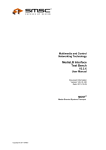
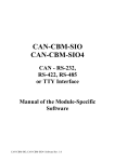
Tx Tester Manual etatronix PMA-3 Transmitter Tester Manual TxTester_Manual_rev1.02.docx 1 Tx Tester Manual Version Version Status Changes Date Responsible 1 1.01 1.02 Release Release Draft Initial release Updated Figure 4 for better visibility Added chapter “Guided test procedure” Updated some pictures 01. Apr. 2015 04. May 2015 15. May 2015 CW CW CW Definitions and abbreviations Abbreviation GUI Tx Rx DUT EOP EOC Description Graphical User Interface Power Transmitter Power Receiver Device Under Test End-of-Power End-of-Charge References Nr. Document 1 PMA Transmitter Compliance Test Procedures System Release 1; PMA-CD-0008-0 v1.00 TxTester_Manual_rev1.02.docx 2 Tx Tester Manual Table of contents 1. Introduction .........................................................................................................................................5 2. Getting ready .......................................................................................................................................6 3. 4. 2.1. Connecting the board and installing drivers ........................................................................6 2.2. Starting the GUI ..........................................................................................................................6 2.3. Using the device .........................................................................................................................8 2.4. Connecting an external load....................................................................................................9 Detailed information about the GUI............................................................................................ 10 3.1. Status information .................................................................................................................. 10 3.2. Modulation tab ........................................................................................................................ 11 3.3. Load tab..................................................................................................................................... 12 3.4. DC/DC tab ................................................................................................................................. 13 3.5. Data manipulator tab ............................................................................................................. 14 3.6. Identification tab...................................................................................................................... 15 3.7. Setup tab ................................................................................................................................... 17 3.8. Update tab ................................................................................................................................ 18 Configuring the GUI for compliance tests.................................................................................. 19 4.1. Alignment Aid ........................................................................................................................... 19 4.2. Placement Detection .............................................................................................................. 19 4.3. Digital Ping – Frequency Sweep ........................................................................................... 19 4.4. Digital Ping – Advertising of Tx-Type ................................................................................... 20 4.5. Digital Ping – Receiving of Rx-Data ...................................................................................... 21 4.6. Identification – Minimal Ping Frequency & Stabilization Subphase ............................. 21 4.7. Identification – RXID ................................................................................................................ 22 4.8. Identification – RXID-Retry Attempt..................................................................................... 22 4.9. Communication – Data Demodulator ................................................................................ 23 4.10. Charging Performance – Frequency Range during Power Transfer phase ........... 26 4.11. Charging Performance – User Indication ...................................................................... 26 4.12. Charging Performance – Audible Noise ......................................................................... 26 4.13. Power Termination – Regular EOP .................................................................................. 26 4.14. Power Termination – Over Temperature....................................................................... 26 4.15. Power Termination – Data Loss ....................................................................................... 27 TxTester_Manual_rev1.02.docx 3 Tx Tester Manual 5. 4.16. Power Termination – Over Decrement .......................................................................... 27 4.17. Power Termination – Over Current................................................................................. 27 4.18. Power Termination – Over Voltage Protection ............................................................. 27 4.19. Power Termination – Foreign Object Detection........................................................... 27 4.20. Functionality - Input voltage range.................................................................................. 27 4.21. Functionality - Misalignment support ............................................................................. 27 4.22. Functionality – Tx power delivery .................................................................................... 27 4.23. Functionality – System efficiency ..................................................................................... 27 Guided test procedure ................................................................................................................... 28 TxTester_Manual_rev1.02.docx 4 Tx Tester Manual 1. Introduction This document is intended to give the user a guide at hand to configure the Tx Tester made by etatronix. This document will detail the functionality of the Tx Tester and give instructions for the configuration of the GUI and Tx Tester needed to conduct the tests described in the Tx Compliance Test Procedure Document. The Tx Tester is developed as a development and testing tool for developers as well as test laboratories. The vast amount of configurable behavior allows a developer to test his product under different aspects. Varying load scenarios, different levels of modulation, checking for robust demodulation and message decoding are among the features of the Tx Tester. All functionalities are designed to conduct certification testing according to the official PMA Compliance Test Procedures document, giving test labs an easy to use tool for manual testing. As a licensed add-on the guided test procedure extension can be bought, which allows the operator to easily perform the compliance tests required by the PMA. Additionally the license includes calibrated correction factors to ensure highest accuracy for measurements. TxTester_Manual_rev1.02.docx 5 Tx Tester Manual 2. Getting ready The Tx Tester is a package of hardware components and a graphical user interface (GUI). The picture below is showing the hardware components. Included in the case are: Tx Tester mainboard Up to three resonant tanks USB thumb drive µUSB cable 24 pin ribbon cable Figure 1: Picture detailing the contents of the package. The thumb drive contains the necessary software as well as all documents and license files. 2.1. Connecting the board and installing drivers To power the Tx Tester board, simply attach the Micro-USB cable to the board and a PC. Any PC should prompt a dialog to inform about the connection of a USB device and demand the installation of the driver needed to communicate with the board. Any operating system released after Windows 7 should install the drivers automatically, if Windows Update can find them. If the drivers are not installed automatically please download the D2XX interface drivers for the FTDI FT200XD chip from the website of FTDI (http://www.ftdi.com) or from the attached thumb drive. 2.2. Starting the GUI After the installation of the drivers in chapter 2.1 you can start the GUI with the PMAtype3TxTester.exe. Figure 2 is showing the start screen of the GUI. TxTester_Manual_rev1.02.docx 6 Tx Tester Manual Figure 2: The start screen of the etatronix TxTestHead GUI. Figure 3: The Tx Tester connected to a PC via USB with GUI open. TxTester_Manual_rev1.02.docx 7 Tx Tester Manual 2.3. Using the device To operate the device the user has to attach the resonant tank to the main PCB. This can be done by attaching the resonant tank to the bottom connectors of the main PCB (no direction required) or by using the enclosed 20 pin ribbon cable. Now the resonant tank has to be brought close to the active surface of a PMA type 3 transmitter. The transmitter will detect the resonant tank and establish a wireless power transfer. The GUI gives information on the current state of the energy transmission (see chapter 3 for detailed information). While operating the device the user has to ensure some safety regulations are met: This device has limited built-in ESD protection. The leads should be shorted together or the device placed in conductive foam during storage or handling to prevent electrostatic damage. High voltages exceeding 50V can occur. Handle with care! Use the development tool in laboratory/development environments by technically qualified electronics experts who are familiar with the dangers and application risks associated with handling electrical mechanical components. Some parts can heat up to high temperatures exceeding 50°C. Burns can occur! TxTester_Manual_rev1.02.docx 8 Tx Tester Manual 2.4. Connecting an external load The user has the ability to connect an external load to the Tx Tester, in case the onboard load resistors are not suitable for the intended use. This can be done via the 16 pin connector next to the µUSB port. Figure 4 is detailing the pins needed to connect the load. Figure 4: The pins needed to connect an external load to the Tx Tester. The four pins closest to the bottom (as viewed in the above figure) are the positive output voltage, the four pins above are the ground connections. TxTester_Manual_rev1.02.docx 9 Tx Tester Manual 3. Detailed information about the GUI This section of the manual is focusing on the different tabs of the GUI and explaining the functionality embedded in these tabs. 3.1. Status information The lower section of the GUI interface is displaying status information on the wireless power transfer. The upper part of the status section is displaying values for: Rectified voltage Operating frequency Input voltage Input current Output voltage Output current Temperature of the onboard load resistors Temperature of the onboard modulation resistors A green square indicating power transfer phase Figure 5: Highlighting the status section of the GUI. The lower part of the status section is showing an image detailing the points of measurement for some of the values mentioned above. This allows the user to understand better, where in the system the respective value is found. Additionally the value for the output power is displayed above the DC/DC section of the image, giving the output power in W. TxTester_Manual_rev1.02.docx 10 Tx Tester Manual 3.2. Modulation tab The modulation tab is used to adjust the values of the modulation capacitors or modulation resistors. This allows the user to reduce or increase the modulation depths of the transmitted signals. The tab is separated horizontally between modulation capacitors and resistors. The allowed values are mentioned directly under the heading of each section. The actual value of the currently used modulation method is displayed under the textboxes and is displayed via the checkboxes as well. Figure 6: The modulation tab of the Tx Tester GUI. To change the value of the modulation capacitors/resistors the user can enter the desired value in the textboxes and the GUI will check if the value is in range and it will calculate the closest match to the desired value. Alternatively the user can change the value by un/checking the checkboxes. Changes are performed immediately when clicking a checkbox or hitting ENTER in the textboxes. TxTester_Manual_rev1.02.docx 11 Tx Tester Manual 3.3. Load tab The load tab enables the user to define the load which is powered through the wireless link. The checkbox “minimal load” enables a 162 Ohm resistor which is connected directly to the rectified voltage. This minimal load is automatically activated if a load is requested that is bigger than 162 Ohm to prevent the rectified voltage from rising too high. The minimal load can be deactivated manually. Figure 7: The load tab of the Tx Tester GUI. To enable a load at the output of the Tx Tester, the “Onboard Load” checkbox has to be activated. The user can enter a desired load value in the textbox. Comma values are acceptable as well. The GUI will calculate the closest match and enable the load. The checkboxes on the right are just for information purposes and are showing the activated onboard load resistors. To prevent the onboard load resistors from over-temperature events a temperature monitoring is implemented, which disengages and prohibits the 2.5, 5 and 10Ω resistors from the output when the temperature reaches 60°C. Once the over-temperature condition is removed and the load resistors were allowed to cool down to 45°C (15°C hysteresis) they are reengaged. The last checkbox enables the external load, meaning that the user can connect his own load to the board. This is useful for longtime / high load test cases, where the onboard load’s overtemperature protection is preventing a good result. TxTester_Manual_rev1.02.docx 12 Tx Tester Manual 3.4. DC/DC tab The user can set a regulated dc voltage (which has to be lower than the rectified voltage), by enabling the DC/DC checkbox and entering the desired value in the textbox. The value has to be in mV. Upon hitting ENTER the value will be set, as can be seen in the status information segment of the GUI. Figure 8: The DC/DC tab of the Tx Tester GUI. Alternatively the user can have a direct feed of the rectified voltage at the output by enabling the DC/DC bridge checkbox. The output voltage will then equal the input voltage in the status section of the GUI. TxTester_Manual_rev1.02.docx 13 Tx Tester Manual 3.5. Data manipulator tab The data manipulator tab allows the user to interfere with the standard PMA compliant behavior of the Tx Tester. The left column of the tab allows the user to send user-defined standard PMA signals instead of the normally transmitted signals by the receiver to adjust its operating point. Be aware that the power transmission from the Tx to the Tx Tester should already be established. Otherwise this feature will have no effect and prevent the Tx Tester from establishing a power transmission with the Tx. (To establish a power transfer, select “Default (PMA Receiver)” and replace the Tx Tester on the Tx.) Figure 9: The data manipulator tab of the Tx Tester GUI. The user activates this feature by checking the “user defined data” checkbox. By entering the number of consecutive signals the user wants to send and clicking the desired message button (either PMA Dec, Inc, NoChange or End-of-Charger/End-of-Power) the Tx Tester will transmit the selected amount of consecutive signals, followed by NoChange signals until the user decides to send another package of user defined messages or resuming standard operation by clicking the “Default” checkbox. The right column allows the user to conduct a test for the transmitter, by disabling communication totally after the specified amount of time. This time is measured from the first sent signal of the default PMA receiver configuration. With the repeat textbox the user can decide how often this behavior should be repeated in cases where the transmitter is repeatedly pinging for a receiver after the loss of communication. TxTester_Manual_rev1.02.docx 14 Tx Tester Manual 3.6. Identification tab The identification tab is giving the user extensive abilities to check the Tx’s abilities to perform according to the PMA specification. The top left section is called “Advertising Type”. By clicking the “Advertising” button, the Tx Tester is set into a decoding and logging mode, which allows capturing and interpretation of the Advertising message the Tx should transmit three times at the beginning of the power transfer. These three messages are decoded and the result is displayed in the section to the left of the “Advertising” button. Furthermore the result is stored in a log file in the %APPDATA%/etatronix/TxTester/logs” folder. The log file is saved with a date and time code. Figure 10: The identification tab of the Tx Tester GUI. Below the “Advertising Type” section is the “RxResponse” section which allows the user to transmit a custom Rx response at the beginning of the ping phase of the power transfer. By checking “User defined” the user gets access to the settings which allow setting of the user defined response. The user can chose the amount of consecutive signals for up to three different signals via the “#” textboxes. The checkboxes to the right allow the choosing of the signal to send. The user can chose between the three standard PMA signals (that is PMA-Inc, Dec and NoChange). When clicking one signal in a row, the other signals in that row will be deactivated. If the user does not want to send three different signals, a row can be deactivated by unchecking every option in that row. The repeat counter specifies the amount of pings to which the Tx Tester should respond in the desired manner. To the right one can find the “RXID” section. Here the user can change the RXID message to check if the Tx is decoding the RXID message correctly. One can change the actual message by altering the “Byte” column, or one can activate and deactivate the sending of the start and stop bits with the checkboxes under the start and stop columns. Furthermore the user has the ability to change the standard configuration for start and stop-bits from “0” to “1” and vice TxTester_Manual_rev1.02.docx 15 Tx Tester Manual versa. The “Calc CRC” button is calculating the CRC bytes based on the current values of the textboxes in the GUI, freeing the customer from having to hand-calculate the CRC every time. The “Rpt #” once again determines how many digital pings should be answered with the custom RXID message. TxTester_Manual_rev1.02.docx 16 Tx Tester Manual 3.7. Setup tab The setup tab gives some information about the currently used version of the GUI and the firmware. The “Reset GUI config” button will reset the GUI configuration to the start values. The “Open Log Folder” will open the explorer in the %APPDATA%/etatronix/Tx Tester/logs folder, where the logs of the decoded Advertising messages are stored. Otherwise the data displayed here is purely informative for in depth knowledge of the system. Figure 11: The update tab of the Tx Tester GUI. TxTester_Manual_rev1.02.docx 17 Tx Tester Manual 3.8. Update tab The update tab allows the user to update the firmware of the Tx Tester easily through the GUI. The Tx Tester has to be connected to the PC through USB. By clicking the “Load S19” button the Tx Tester is set into bootloader mode (red led is off) and a file dialog opens, where the user has to choose the S19 file which should be transferred to the Tx Tester. The firmware will then be downloaded to the Tx Tester. A progress bar will inform the user about the state of the update. When the download finished successfully a message box will appear informing of the successful update. In the rare case the download was not successful the user will be informed to power cycle the device and try again. Figure 12: Update is performed successfully. TxTester_Manual_rev1.02.docx 18 Tx Tester Manual 4. Configuring the GUI for compliance tests This chapter will detail the steps necessary to configure the GUI and the Tx Tester board for the respective compliance test according to the PMA Transmitter Compliance Test Procedures - System Release 1 - V1.00 document released by the PMA. 4.1. Alignment Aid No configuration needed. Test is done without Tx Tester. 4.2. Placement Detection To configure the Tx Tester for this test, make sure it is removed from the DUT, as described in the Tx Compliance Test Procedure Document. To configure the Tx Tester to not react on a Digital Ping (that is to disable communication) the user has to switch to the “Data manipulator” tab. By checking the Data loss checkbox the user is getting access to a set of parameters which control when a data loss (that is no communication between Tx Tester and DUT) shall occur. By setting it to 0ms after the start of RxResponse, communication is disabled from the start. The amount of retries can be defined with the next textbox. The exact number of retries depends on the operator, since this test requires the capturing of an analog pulse followed by a digital ping while moving the Tx Tester horizontally on the Tx surface. By clicking the “data loss” button those values are transferred to the Tx Tester. 4.3. Digital Ping – Frequency Sweep No configuration is needed. Standard operation is sufficient to perform this test. TxTester_Manual_rev1.02.docx 19 Tx Tester Manual 4.4. Digital Ping – Advertising of Tx-Type To configure the Tx Tester for this test, make sure it is removed from the DUT, as described in the Tx Compliance Test Procedure Document. Figure 13: After the decoding of the Advertising Type Message the result is displayed in the Advertising Type section. Go to the tab “Identification” and click the button “Advertising”. The label in the advertising type section will read “Not available”. Once the DUT is powered and the Tx Tester is placed on the DUT’s surface, the Tx Tester will decode the advertising type message of the DUT and display the result as the 12bit value. The user will have to verify the correctness of the message. A log of the decoded messages is created in the %APPDATA%/etatronix/TxTester/logs folder with a date and time stamp. TxTester_Manual_rev1.02.docx 20 Tx Tester Manual 4.5. Digital Ping – Receiving of Rx-Data After the advertising message from the Tx, a Rx is supposed to send a Rx response to the Tx. The standard response which will be sent when the checkbox “Default” in the RxResponse section of the “Identification” tab is checked, is 5-15 PMA Dec signals. The user has the ability to send a user defined response which can be made of up to three different PMA signals and the user can configure the amount of consecutive signals per PMA signal via textboxes. There is also the possibility to send only one command by simply disabling the checkboxes for unwanted PMA signals. The user can set the number of resends of the user defined Rx response via the “Rpt #” textbox. The number of resends defines at how many digital pings the Tx Tester will give this response. This allows the user to validate the DUT transits to the standby phase after N retries. Figure 14: Configuration of the Tx Tester for a user defined Rx response. Before clicking the RxResp button the user has to ensure, the Tx Tester in not placed on the DUT’s surface, as described in the Tx Compliance Test Procedure Document. The user defined response will be repeated 5 times to allow validation of the “Receiving of RxData” test. The Tx tester will continue to act as a standard PMA Rx once the test has been completed or after a 30s timeout if no power signal has been detected. 4.6. Identification – Minimal Ping Frequency & Stabilization Subphase The configuration for this test is done in the same way it was done for 4.5 Digital Ping – Receiving of Rx-Data. TxTester_Manual_rev1.02.docx 21 Tx Tester Manual 4.7. Identification – RXID No configuration needed. Conformance to this requirement is self-declared by vendor. 4.8. Identification – RXID-Retry Attempt To provoke a RXID-Retry attempt by the Tx, the Tx Tester has to alter the RXID message to send wrong information or corrupt the packet frame. Figure 15: The interface to change the RXID message. This can be done in the RXID section of the “Identification” tab. By clicking “User defined”, the user has the ability to change the RXID message. The checkboxes under the start and stop column enable or disable the corresponding start or stop bits in the packet frame of the RXID message. The textboxes under the start and stop column allow the user to change the start and stop bits between “1” and “0”. The textboxes under the byte column allow the user to change the value of the respective byte. Clicking the Calc CRC button will calculate the CRC based on the current values of the byte column. The “Rpt #” textbox sets the number of digital pings answered with this custom RXID. This allows the user to validate the DUT transits to the standby phase after N retries. By clicking the RXID button the current configuration for the RXID message will be sent by the next placement of the Tx Tester on the DUT’s surface. TxTester_Manual_rev1.02.docx 22 Tx Tester Manual 4.9. Communication – Data Demodulator To configure the Tx Tester for this test, first switch on the “minimal load” in the “load” tab. The user has to ensure that the onboard and external load are deactivated. Figure 16: Only the minimal load may be activated for the first part of this test. To operate with maximum capacitive modulation, please change to the “Modulation” tab and activate all the checkboxes for capacitive modulation. Figure 17: The modulation tab configured for maximum capacitive modulation. TxTester_Manual_rev1.02.docx 23 Tx Tester Manual To reduce the modulation capacity either uncheck the boxes or use the textbox to enter a value. The GUI will calculate the closest possible match to the desired value. To configure the Tx Tester for modulation test at maximum load, the user has to enable the dc-output of the Tx Tester first. Change to the “DC/DC” tab and enter a value of 5000mV in the textbox and hit enter. To make sure the value is set the user should verify the value of the “Output Voltage Vout” in the information section of the GUI. Figure 18: Configuration for 5V DC/DC at the output. Set the load to 5Ω via the “Load” tab. To do this, check “OnBoard Load” and enter 5, hit ENTER. Check the information section of the GUI to verify that output current is flowing. TxTester_Manual_rev1.02.docx 24 Tx Tester Manual Figure 19: Configuration for 5Ω load. TxTester_Manual_rev1.02.docx 25 Tx Tester Manual 4.10. Charging Performance – Frequency Range during Power Transfer phase The configuration for this test is done in the “Data manipulator” tab. By clicking “User defined” the user is getting access to a set of buttons, which enable the sending of customized PMA messages. As long as Default (PMA Receiver) is not checked, the Tx Tester will not send any data to change its operating point. Figure 20: The data manipulator tab enables the user to send customized PMA messages. By entering the number of signals and clicking the desired PMA message button, the number of desired signals will be sent. 4.11. Charging Performance – User Indication No configuration needed. Conformance to this requirement is self-declared by vendor. 4.12. Charging Performance – Audible Noise No configuration needed. Conformance to this requirement is self-declared by vendor. 4.13. Power Termination – Regular EOP An EOP event can be issued by sending 50 EOC commands from the Tx Tester to the DUT. This can be done via the “Data manipulator” tab (See chapter 0 for details on the configuration). 4.14. Power Termination – Over Temperature No configuration is needed for this test. The GUI is just for observation. TxTester_Manual_rev1.02.docx 26 Tx Tester Manual 4.15. Power Termination – Data Loss To configure a data loss scenario change to the “data manipulator” tab. By checking the “data loss” checkbox the interface for this test is activated. The first textbox allows the user to set the time after how many ms data loss will occur. The second textbox sets the number of retries. 4.16. Power Termination – Over Decrement The configuration for this test is based on the functionality of the “Data manipulator” tab. See chapter 0 for details on the configuration. 4.17. Power Termination – Over Current An over current event can be triggered by selecting a big load at the output. First, set the Tx’s operating point at the lowest possible frequency by sending 100 PMA DEC-signals via the “data manipulator” tab as described in chapter 4.10. To set a load at the output refer to chapter 4.9. The load can be further increased by selecting load resistor values smaller than 5Ω. Additionally the spatial distance between Tx and Tx Tester surface can be further increased to trigger an over current event. 4.18. Power Termination – Over Voltage Protection An over voltage event can be triggered in the same way an over current event is triggered. See the previous chapter 4.17 for configuration. 4.19. Power Termination – Foreign Object Detection No configuration needed. Conformance to this requirement is self-declared by vendor 4.20. Functionality - Input voltage range No configuration needed. 4.21. Functionality - Misalignment support No configuration needed. 4.22. Functionality – Tx power delivery No configuration needed. Conformance to this requirement is self-declared by vendor. 4.23. Functionality – System efficiency No configuration needed. Conformance to this requirement is self-declared by vendor. TxTester_Manual_rev1.02.docx 27 Tx Tester Manual 5. Guided test procedure The guided test procedure implementation in the GUI can be found on the right side of the GUI. This feature is based on the released official Transmitter Test Procedure document by the PMA and is available as a licensed upgrade. Figure 21: The guided test procedure section of the GUI. The guided test procedure is configuring the Tx Tester to perform the tests specified in the procedure document with just a click. For the user it is as simple as choosing the desired test from the tabs and clicking through steps. No in depth knowledge of the program is required. This implementation is reading the instructions needed to perform the test according to the compliance test procedures document, like setting up the measurement equipment and connecting the DUT. The configuration to perform the test is done automatically. TxTester_Manual_rev1.02.docx 28