1
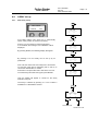
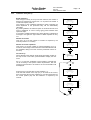
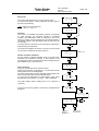
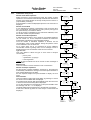
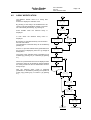
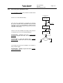
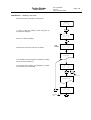
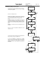
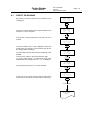
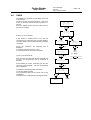
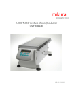
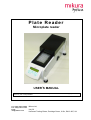
Plate Reader
Microplate reader
USER’S MANUAL
This manual contains Mikura Ltd reserved information. All rights reserved. Unauthorized copying of this
manual or part of it is prohibited.
Tel: +44(0) 1403 710298
Fax: +44(0) 1403 711810
Email:
[email protected]
Mikura Ltd,
Unit 30
Huffwood Trading Estate, Partridge Green, W Sx, RH13 8LE, UK
Optica Reader
USER’S MANUAL
Type
Date
Doc. 600.6000
Rev.00
Date:24-March-2004
Modifications
Page 2
Optica Reader
USER’S MANUAL
Doc. 600.6000
Rev.00
Date:24-March-2004
Page 3
CONTENS
INTRODUCTION..........................................................................................................................................................................5
0.1. DESCRIPTION................................................................................................................................................................5
0.2. WARRANTY...................................................................................................................................................................5
0.2.1
Asking for service .....................................................................................................................................................5
0.2.2
Ordering spare parts ................................................................................................................................................6
0.3. CE CONFORMITY .........................................................................................................................................................6
SECTION 1 - GENERAL SAFETY WARNINGS ......................................................................................................................7
1.1.
1.2.
1.3.
GENERAL SAFETY WARNINGS.................................................................................................................................7
INSTRUMENT WORKING CONDITIONS...................................................................................................................7
INTENDED USE OF THE INSTRUMENT....................................................................................................................7
SECTION 2 - GENERAL INFORMATION ...............................................................................................................................8
2.1.
2.2.
2.3
INSTRUMENT DESCRIPTION: PURPOSE AND FEATURES ...................................................................................8
FEATURES .....................................................................................................................................................................8
TECHNICAL SPECIFICATIONS...................................................................................................................................8
SECTION 3 – INSTALLATION AND START UP ....................................................................................................................9
3.1
PLACING INSTRUMENT..............................................................................................................................................9
3.1.1.
Positioning the instrument........................................................................................................................................9
3.1.2.
Power connection.....................................................................................................................................................9
3.2. PLATE READER COMPUTER CONNECTION ........................................................................................................9
3.3. SET THE INSTRUMENT IN WORKING CONDITION .............................................................................................10
4.2.1.
How to insert the paper ..........................................................................................................................................10
4.2.2.
Micro titer plate positioning...................................................................................................................................10
4.2.3.
Strip positioning .....................................................................................................................................................10
SECTION 4 - HOW TO USE PLATE READER .....................................................................................................................11
4.1. INTRODUCTION..........................................................................................................................................................11
4.2. SWITCHING THE INSTRUMENT ON........................................................................................................................12
4.3. INSTRUMENT SET UP ................................................................................................................................................13
4.3.1.
General...................................................................................................................................................................13
4.3.2.
How to set the date .................................................................................................................................................13
4.3.3.
How to set the time .................................................................................................................................................13
4.3.4.
How to set the Strip type.........................................................................................................................................14
4.3.5.
How to set up a new assay .................................................................................................................................14
4.3.6.
How to modify an assay .....................................................................................................................................14
4.3.7.
How to delete assay ............................................................................................................................................15
4.3.8.
Shaking activation ..................................................................................................................................................15
4.3.9.
Statistical information ............................................................................................................................................16
4.3.10.
Utility .................................................................................................................................................................16
4.4. ASSAY SET UP ...............................................................................................................................................................17
4.4.1.
New Assay set up ....................................................................................................................................................17
4.4.2.
Qualitative Assay Set up.........................................................................................................................................18
4.4.3.
Quantitative assay set up........................................................................................................................................21
4.5. ASSAY MODIFICATION.............................................................................................................................................22
4.6. ASSAY PROCESSING .................................................................................................................................................24
4.6.1.
Assay start up .........................................................................................................................................................25
4.6.2.
How to carry out a qualitative assay......................................................................................................................26
4.6.3.
How to carry out a quantitative assay....................................................................................................................27
4.7. DIRECT OD READING................................................................................................................................................31
4.8. TIMER ...........................................................................................................................................................................32
SECTION 5 - MAINTENANCE .................................................................................................................................................33
5.1. MAINTENANCE AND CHECKS PREVENTIVE MEASURES .................................................................................33
5.1.1.
Cleaning .................................................................................................................................................................33
5.1.2. Instrument testing ................................................................................................................................................33
5.1.3.
Inspection and controls ..........................................................................................................................................33
5.1.4.
Troubleshooting (diagnosis)...................................................................................................................................34
5.2. MAINTENANCE ..........................................................................................................................................................34
Optica Reader
USER’S MANUAL
Doc. 600.6000
Rev.00
Date:24-March-2004
Page 4
SECTION 6 - PACKING, TRANSPORTATION AND STORING.........................................................................................35
6.1.
6.2.
6.3.
6.4.
GENERALITY ..............................................................................................................................................................35
PACKING THE INSTRUMENT...................................................................................................................................35
TRANSPORTATION ....................................................................................................................................................35
STORING THE INSTRUMENT ...................................................................................................................................35
SECTION 7 – APPENDIX ..........................................................................................................................................................36
APPENDIX A............................................................................................................................................................................36
A.1.
INSTRUMENT DECONTAMINATION. .................................................................................................................36
A.1.1.
Decontamination procedure...................................................................................................................................36
A.1.2.
Decontamination declaration.................................................................................................................................37
Optica Reader
USER’S MANUAL
Doc. 600.6000
Rev.00
Date:24-March-2004
Page 5
INTRODUCTION
0.1.
DESCRIPTION
This manual provides the operator with all the necessary instructions and maintenance recommendations
for a safe and suitable use of the instrument.
Manual content:
introduction - warranty information, Technical Service and the CE conformity declaration
section 1 - general safety-warnings
section 2 - general information
section 3 - instrument performance and technical data
section 4 - installation and start up
section 5 - operating instructions
section 6 - periodic maintenance
section 7 - how to put the instrument out of service, packaging, transport and storage
section 8 - appendices including instrument decontamination and spare parts list
This manual is considered as a part of the instrument; it has to be at the operator, user ,and maintenance
technician’s hand at any time. For accurate installation, use and maintenance please read the following
instructions carefully.
In particular carefully read Section 1 “GENERAL SAFETY WARNINGS”, describing the suitable operating
procedures in order to avoid damages to the instrument and people.
In case of breakdowns or any troubles with the instrument, refer to the local Technical Service.
0.2.
WARRANTY
Each provided instrument is completely tested, and guaranteed for twelve months from delivery.
The warranty is for all mechanical and electrical parts. It is granted only for a proper installation, use and
maintenance in compliance to the given instructions contained in this manual.
The warranty does not include any responsibility for direct or indirect to people and material damages,
caused by improper use and maintenance of the instrument.
All parts that are subject to deterioration, because of their specific use, are excluded from the warranty.
Due to a misuse of the instrument the warranty does not include (if requested) the travel and labor-hour
expenses as well as all the accommodation expenses.
0.2.1
Asking for service
When asking for service, refer to this manual indicating also the data reported on the identification label of
the instrument.
Only qualified Technicians with suitable instrumentation and original spare parts are entitled to fix the
instrument; ordinary maintenance should be carried out by the user, as described in this manual.
Optica Reader
USER’S MANUAL
0.2.2
Doc. 600.6000
Rev.00
Date:24-March-2004
Page 6
Ordering spare parts
Parts that are subject to deterioration or that are defective and need to be replaced have to be requested as
shown below.
When ordering spare parts, the following details are to be mentioned:
customer’s purchase order
name and version of the instrument
instrument code number
part code number
part description
requested quantity
name and company address to deliver the ordered goods
Replacing the parts with ORIGINAL SPARE PARTS guarantees effective and lasting instrument life
0.3.
CE CONFORMITY
DECLARATION OF CONFORMITY
The manufacturer:
Mikura Ltd
SCIENTIFIC INSTRUMENTS
Unit 30 Huffwood Trading Estate, Partridge Green W Sx, RH13 8AU.
Tel: +44 (0) 1403 710298, Fax: +44 (0) 1403 711810
PLATE READER
model:
Optica
conforms to the following EC Directives, including the last modifications:
73/23/EC regarding low voltage
89/336/EC regarding Electromagnetic Compatibility
and that the below harmonized standard specifications have been applied:
Safety:
EN 61010 -1 (1997) “Electrical equipment safety requirements for measurement,
control and laboratory use – Part 1: General requirements”
Electromagnetic Compatibility:
EN 61326 -1 (1998) “Electrical equipment for measurement, control and laboratory
use – EMC requirements – Part 1: General requirements”
The Managing Director
Optica Reader
USER’S MANUAL
Doc. 600.6000
Rev.00
Date:24-March-2004
Page 7
SECTION 1 - GENERAL SAFETY WARNINGS
1.1.
GENERAL SAFETY WARNINGS
In this manual the following symbols stand for danger or warnings:
General DANGER symbol. Indicates that not following relative instructions and warnings is a
serious safety risk.
Indicates ELECTRICAL VOLTAGE, which could cause death upon contact. Covers with this
symbol can be removed and replaced by qualified people and only after electrical power
disconnection.
Indicates that the instrument uses reagents and other DANGEROUS CHEMICAL
SUBSTANCES, corrosive, irritating or noxious, which could cause health damages.
Indicates that the instrument handles potentially infectious samples (e.g. body fluids such as
urine) which could cause INFECTION/CONTAMINATION. Always observe the general safety
standard rules for the presence of these biological substances. Wear protective goggles,
gloves and clothing.
Indicates that not following the correct instructions could cause damage to the instrument
and/or its proper functioning.
Indicates important information concerning the instrument or a section of the document that is
important to read with particular attention.
1.2.
INSTRUMENT WORKING CONDITIONS
The instrument is an in vitro diagnostic medical device (IVD) intended to be used in the following working
conditions:
optical density readings as specified in the technical data
use of the chemical reagents and accessories supplied and/or declared to be compatible with
the instrument
working at a specific temperature and humidity level according to the details given in this
manual
do not power the instrument in a potentially explosive or fire hazardous environment
The instrument has to be used as described in this manual. Any other use has to be regarded as
improper
1.3.
INTENDED USE OF THE INSTRUMENT
The instrument has to be used for the expected purpose and in perfect technical conditions, by qualified
personnel, in working conditions and following maintenance operations described in this manual.
This manual contains instructions for qualified operators.
Qualified Users have to make sure that the environment conditions are suitable, the
installation is correct, the use and maintenance are proper, according to the general safety
rules as well as to particular precautions described in the manual (although he is not entitled to
repair the instrument).
Qualified Technicians are entitled to service and fix the instrument with original spare parts,
according to the received instructions.
Modifications of the instrument are not allowed. The user is liable for any improper
modifications and for the consequences deriving from them.
For extraordinary maintenance, ask for licensed service centers. The maintenance will be carried
out by Specialized Technicians that will be able to fix the instrument using original spare parts.
Optica Reader
USER’S MANUAL
Doc. 600.6000
Rev.00
Date:24-March-2004
Page 8
SECTION 2 - GENERAL INFORMATION
2.1.
INSTRUMENT DESCRIPTION: PURPOSE AND FEATURES
The PLATE-READER has been designed to automatically process the optical density reading of a micro
titer plate with 96 wells. The plate has to be separately prepared before the reading process.
2.2.
FEATURES
Purpose
96 well microplate reading
Kind of instrument
Stand alone instrument with its own software, display – keypad, and printer
Intended use
Photometer reading for ELISA/EIA methods
Software for PC
For the use of patient data management (optional)
2.3
TECHNICAL SPECIFICATIONS
Light source
tungsten lamps, automatically under-powered when in stand-by position
Optical filters
2 filters (450, 630 nm); 2 more on request (max 4 filters)
Detectors
8 silicon photodiodes
Reading system
8 independent channels, mono or bichromatic reading
Accuracy
± 1% from 0.000 to 1.500 OD
± 2% from 1.500 to 3.000 OD
Reading time
16s to perform a monochromatic reading on a full plate; 31s for bichromatic reading
Cuvettes
96 well plate or 8x12 or 12x8 well strips
Plate shaking
programmable by keyboard
LCD-Display
2 lines with 16 columns
Printer
External Epson type
Keypad
17 buttons
Interface
RS232 serial port
Curves
curve direct plotting: point to point, linear regression and 4 parameters (log-logit)
Results
by strip of 8 or 12 wells (X or Y)
Calculation Mode
OD, direct Cut-Off or calculated, single calibrator, programmable curves from 2 to 12 points
Memory capacity
170 tests
Calendar/Timer
associates time with the results; timer function
Power
requirements
230/115 VAC, 50-60 Hz, 110 W
Measurements
cm 58 x 24 x 23
Weight
8.4 Kg
Items supplied with
the instrument:
•
•
A.C. power Cable.
user’s manual
Additional
accessories
(optional)
•
•
PC cable connection
PC communication software
Optica Reader
Doc. 600.6000
Rev.00
Date:24-March-2004
USER’S MANUAL
Page 9
SECTION 3 – INSTALLATION AND START UP
When installing and setting up the instrument, follow the safety warnings and general rules described in
Section 1.
3.1
PLACING INSTRUMENT
3.1.1.
Positioning the instrument
The instrument has to be placed on a leveled bench, assuring enough free space around the instrument to
allow maintenance operations. The instrument has to be kept in a room where temperature has to
o
be between 15 and 35 C with relative humidity below 80%, and protected from direct sun light.
3.1.2.
Power connection
Once the instrument has been placed in the desired position proceed with plugging it into the right power
source 230VAC or 115VAC (see label) using the proper cable.
Warning: make sure that the electrical power is the one as requested and indicated on the
identification label of the instrument !
Warning: make sure that the fuses correspond to the ones indicated on the identification label of the
instrument and in the manual!
230 Vac
n° 2 quick fuses 0.25 A
115 Vac
n° 2 quick fuses 0.5 A
3.2.
PLATE READER
COMPUTER CONNECTION
The instrument is equipped with an RS232 serial port for PC connection.
A cable and software are optionally available to link the instrument to PC (IBM or compatible in order to print,
transfer and record the acquired data.
Connection to the PC must be made through the serial port COM2. Generally there are two serial ports to choose
from, located on the rear of the PC: COM1 with a 9 pin male connector (for mouse connection) and COM2 with a 25
pin male connector.
•
8 bit
•
600 baud rate
•
no parity
•
stop bit
Optica Reader
USER’S MANUAL
Doc. 600.6000
Rev.00
Date:24-March-2004
3.3.
SET THE INSTRUMENT IN WORKING CONDITION
4.2.1.
Connect the serial printer lead to the printer port on Optica and to the printer
Page 10
We recommend that you use tractor fed paper as this allow uninterrupted printing
Note: For a good printing, the use of original paper is recommended
4.2.2.
Micro titer plate positioning
The micro titer plate should be placed onto the carriage, making sure that it is properly oriented.
H12
A1
4.2.3.
Strip positioning
Instrument reading system :
8 wells strip format
12 wells strip format
strip with 8 wells:
1 2 3 4 5 6 7 8
strip 1
1A, 1B, 1C,
1H
strip 2
2A, 2B, 2C,
2H
strip 12
12A, 12B, 12C,
12H
Strip with 12 wells:
1 2 3 4 5 6 7 8 9 10 11 12
strip 1
1A, 2A, 3A,
12A
strip 2
1B, 2B, 3B,
12B
strip 8
1H, 2H, 3H,
12H
Optica Reader
Doc. 600.6000
Rev.00
Date:24-March-2004
USER’S MANUAL
Page 11
SECTION 4 - HOW TO USE PLATE READER
4.1.
INTRODUCTION
The flow diagram below indicates how the instrument is used. Detailed information for each step can be
found in the indicated paragraph.
Table 5.1 - General flow diagram
INITIAL
MENU
ASSAY
ASSAY
PROCESSING
DIRECT OD
READING
TIMER
FUNCTION
INSTRUMENT
SETUP
SET TIME
SET DATE
SET MINUTES
SET SECONDS
SET TIME
STRIP TYPE
NEW ASSAY
MODIFY ASSAY
DELETE ASSAY
SET SHAKING
SHOW
STATISTIC
UTILITY
Optica Reader
USER’S MANUAL
4.2.
Doc. 600.6000
Rev.00
Date:24-March-2004
Page 12
SWITCHING THE INSTRUMENT ON
The safety warning and general rules described in Section 1 have to be observed when using the
instrument
When switched on, the instrument automatically
checks the functionality of its main parts; it
prints the heading containing the instrument
name, the software revision, the actual date
and time, it checks the plate carriage home
position.
Then the initial menu is shown as in fig. 1
Select one of the two options as shown on the
display lower line (ASSAY or TIMER) by
pressing the function keys F1 or F2
fig. 5.1 Initial menu
When this initial menu is displayed the SET and PAPER buttons assume specific functions:
• SET button is to modify some parameters (for example date and hour, as specified in the SET menu
chapter);
• PAPER does not function on this model
• When in this menu, ENTER button (usually it allows to enter data when required on the specific menu)
is not enabled.
• ESC usually allows to go back to the previous menu
NOTE: SET, PAPER and ENTER, in particular menus can change their function as after explained.
Optica Reader
USER’S MANUAL
Doc. 600.6000
Rev.00
Date:24-March-2004
Page 13
4.3.
INSTRUMENT SET UP
4.3.1.
General
By pressing SET button when in the initial menu (fig. 1), some instrument parameters can be modified. In
the succeeding phases use ESCAPE to go back to the initial menu, use SET to go to the next menu.
4.3.2.
How to set the date
This menu is to modify the instrument internal date.
CHANGE DATE
continue
SET
CH A N G E D A TE
con tin ue
c han ge
----- ----- ----- -------- ----- ---F1
F2
SET
change
F1
F1
F2
CHANGE DATE
menu
F2
DAY [15 ] = _
-- ----- ----- --- ----- ----- ----- -F1
F2
By pressing SET or F1 the next menu is displayed,
otherwise press F2 to change the date.
ENTER/ESC
MONTH [9] = _
The display shows in brackets the memorized day, month
and year; modify the values if necessary and press
ENTER, if no modification is required press ESCAPE.
-------------------------------F1
F2
ENTER/ESC
YEAR [98] = _
-------------------------------F1
F2
Go back to menu
CHANGE DATE
4.3.3.
ENTER/ESC
How to set the time
This menu is to modify the instrument internal time.
CHANGE TIME
continue
SET
SET
change
CH A N G E T IME
con tin ue
c han ge
---- --- -- - -- - -- -- - -- -- - -- - -- -- - F1
F2
F1
F1
F2
STRIP TYPE
menu
F2
HO U R [0 9] = _
-- --- ---- --- --- -- --- -- - -- - -- -- - F1
F2
By pressing SET or F1 the next menu is displayed,
otherwise press F2 to CHANGE the time.
ENTER/ESC
The display shows in brackets the memorized hour,
minutes and seconds; modify the values if necessary and
press ENTER, if no modification is required press
ESCAPE.
MIN. [35] = _
-------------------------------F1
F2
ENTER/ESC
SEC. [28] = _
-------------------------------F1
F2
Go back to
CHANGE TIME
menu
ENTER/ESC
Optica Reader
USER’S MANUAL
4.3.4.
Doc. 600.6000
Rev.00
Date:24-March-2004
Page 14
How to set the Strip type
This menu is to set the strip type configuration on the
micro titer plate:
#12 strips with 8 wells
1 2 3 4 5 6 7 8
#8 strips with 12 wells
1 2 3 4 5 6 7 8 9 10 11 12
SET
STRIP TYPE
continue
change
F1
STRIP TYPE
continue
change
SET
-------------------------------F1
F2
F2
By pressing SET or F1 the next menu is displayed,
otherwise press F2 to change the strip type.
F1
F2
NEW ASSAY
menu
STRIP TYPE
[8]
12
The display shows in brackets the memorized Strip type,
(8 or 12).
Select [8] or [12] by pressing F1 or F2 and press ENTER;
if no modification is required press ESCAPE.
F1\F2
-------------------------------F1
F2
EN TER/ESC
4.3.5.
How to set up a new assay
This menu is to set up a new assay.
SET
NEW ASSAY
continue
F1
new
NEW ASSAY
con tin ue
SET
new
-------------------------------F1
F2
F2
F1
F2
Press F1 to display the next menu or press F2 to run the
procedure to set a new assay.
This procedure is described in details in para. 5.4 - New
assay set up.
4.3.6.
Go to procedure
NEW ASSAY SET UP
(SEE TABLE A2 AND PARA. 5.4)
Go to
MODIFY ASSAY
menu
How to modify an assay
The MODIFY ASSAY menu is to modify filed assays.
MODIFY ASSAY
continue
SET
modify
MODIFY ASSAY
con tin ue
F1
m o dif y
-------------------------------F1
F2
F2
SET
Press F1 to display the next menu or press F2 to start
the modification procedure .
F1
This procedure is described in details in par. 5.5 - Assay
modification.
F2
Go to procedure
ASSAY MODIFICATION
(SEE TABLE A3 AND PARA. 5.5)
Go to
DELETE ASSAY
menu
Optica Reader
USER’S MANUAL
4.3.7.
Doc. 600.6000
Rev.00
Date:24-March-2004
Page 15
How to delete assay
DELETE ASSAY menu allows to delete filed assays.
SET
DELETE ASSAY
con tin ue
SET
DELETE ASSAY
continue
delete
F1
F1
F2
F2
SELECT ASSAY
number
all
-------------------------------F1
F2
GO TO
SHAKING MENU
By pressing F1 the next menu is displayed, by
pressing F2 it is possible to delete some or all the
filed assays.
When F2 key is pressed, in order to avoid
fortuitous mistakes, a further confirmation, before
deleting all the filed assays, is required.
If F1 is pressed, the identification number of the
assay to be deleted is required, then press
ENTER.
Before deleting the selected assay a confirmation
is required. Then the menu DELETE ASSAY is
displayed again.
4.3.8.
F1
DEL. ALL ASSAY ?
yes
no
-------------------------------F1
F2
ENTER
F1/F2
N.1 "NAME"
exit
clear
-------------------------------F1
F2
Go back to
DELETE ASSAY
menu
F1/F2
Go back to
DELETE ASSAY
menu
SET
The SHAKE menu allows to activate the plate
SHAKING, this function has to be activated before
the reading process.
SHAKING
continue
set
SET
-------------------------------F1
F2
F1
SHAKING
F1
F2
ENTER NUMBER : _
( 0 for list)
-------------------------------F1
F2
Shaking activation
continue
del ete
-------------------------------F1
F2
set
Go to
STATISTICS
menu
F2
F2
DURATION = _
(from 1 s to 60 s)
-------------------------------F1
F2
SPEED = _
(fr om 1 to 5)
-------------------------------F1
F2
By pressing F1, the next menu is accessed.
EN TER
F2 key is to set the plate shaking duration, as
well as the shaking speed.
Go back to menu
SHAKING - set
SHAKING
-------------------------------F1
F2
A shaking cycle
as setted up
is performed
Optica Reader
USER’S MANUAL
4.3.9.
Doc. 600.6000
Rev.00
Date:24-March-2004
Page 16
Statistical information
SET
The STATISTICS menu is to list working data
information.
STATISTICS
continue
STATISTICS
continue
show
-------------------------------F1
F2
SET
show
F1
F1
F2
F2
Press F2 to check the number of hours the
instrument has been working as well as the
number of performed reading.
After 5 seconds, the STATISTICS menu is
displayed again.
WORK HOURS = 123
N. MEASUR = 4500
-------------------------------F1
F2
go back to language
SELECT MENU
After 5 sec. go back to
STATISTICS menu
4.3.10. Utility
The UTILITY The “SERVICE” menu is to check
the instrument functionality.
STATISTICS
continue
SET
UTILITY
continue
run
-------------------------------F1
F2
SET
show
F1
F1
F2
F2
go back to language
SELECT MENU
SEE TAV. A5
Optica Reader
USER’S MANUAL
4.4.
ASSAY set up
4.4.1.
New Assay set up
Doc. 600.6000
Rev.00
Date:24-March-2004
Page 17
SET
NEW ASSAY
continue
F1
new
NEW ASSAY
continue
new
-------------------------------F1
F2
F2
F2
From NEW ASSAY menu press F2 to automatically
search a free position to store the new assay .
GO TO THE FIRST
FREE POSITION
Press F1 or F2 to search for other free locations.
If not available, the message “FULL MEMORY” will be
displayed.
N. 1 FREE
next
previous
-------------------------------F1
F2
By pressing ENTER, the following display will appear .
ENTER
N. 1 FREE
set
-------------------------------F1
F2
By pressing F2 a new assay can be set up by its
parameters.
First of all, the name of the new assay has to be entered.
To enter the name (max 6 characters) use F1 and F2, to
choose the desired letter or number.
Press SET to accept a letter and to shift to the next one.
F2
NAME = _
next
previous
-------------------------------F1
F2
Once the assay name has been typed, press ENTER.
Then the display will appear to choose for the assay
method to carry out.
The assay is selected by pressing: F1 or F2 to select a
Qualitative or a Quantitative method.
ENTER
METHOD
qu alit.
q uantit.
-------------------------------F1
F2
F1
F2
QUALITATIVE
QUANTITATIVE
Optica Reader
USER’S MANUAL
4.4.2.
Doc. 600.6000
Rev.00
Date:24-March-2004
Page 18
Qualitative Assay Set up
Blank repetitions
After the type of assay to set up has been selected, the number of
blank to be repeated (to choose from 1 to 12) has to be entered: if
no blank is required, enter “0”.
The average of the measured absorbance values regarding the
blank dispensed in the processed strip, will be automatically
calculated.
By pressing ENTER, the selected option is confirmed and the next
menu is displayed. In case of wrong typing press ESCAPE then
repeat the input.
If more than 12 blank repetitions have been selected, is displayed a
message to set again the right number of blank repetition to carry
out.
BLANK REPET. = _
(from 0 to 12 )
-------------------------------F1
F2
ENTER
# OF CONTROLS = _
( from 1 to 12 )
-------------------------------F1
F2
ENTER
Number of controls
This menu is to set the number of controls as required by the
method (maximum 12 controls).
CONTROL REPET. = _
( from 1 to 12 )
-------------------------------F1
F2
Number of control repetitions
This menu is to set the number of controls repetitions up to 12
maximum; the average of the measured controls absorbances will
be calculated, taking in account of all the processed controls of
that strip.
ENTER
Cut-off set up
When allowed by the method, simply enter the position number of
the strip for the cut-off value, press ENTER to display the next
menu.
Set “0” to enter the coefficients of the formula to calculate the
cut-off according to the specific method requirements, then the
structure of the formula to be used for the cut-off calculation will
be displayed.
CUT-OFF POS. = _
(0 for formula )
-------------------------------F1
F2
NO
pos. = 0 ?
YES
INPUT FORMULA
Press any key to set the value for the coefficient “a”,
enter the well number of the strip (C1) to be used for the control,
then set the the value for the coefficient “b” and the well number for
the control position (C2) and the coefficient “c” required by the
formula.
a*C1+b *C2+c
-------------------------------F1
F2
ENTER
a =_
a=_
C1 = _
a*C1+b*C2+c
-------------------------------F1
F2
b=_
C2 = _
c=_
ENTER
RATIO FACTOR
MENU
Optica Reader
USER’S MANUAL
Doc. 600.6000
Rev.00
Date:24-March-2004
Page 19
Examples
Some typical cases are afterwards analyzed to indicate the way to set the parameters for the cut-off
calculation as required by the specific method.
Example 1
Having 3 controls (NC, PC, HC), supposing to calculate the cut off
according to the Absorbance values average of the negative and
positive controls [O.D. (NC) = NC, O.D. (HC) = HC]:
cut-off = (NC + HC) / 2
Considering that the (1) formula can be written as following:
cut-off = NC / 2 + HC / 2
comparing this formula with the one provided by the instrument sa
described:
cut-off = a × C1 + b × C2 + c (2)
(1)
it is possible to calculate the cut-off value as required by the method,
assigning to the coefficients “a”, “b” and “c” the following values (2):
a = 0, 5
As the (1) involves the first and third control, has to be set for the C1
and C2 coefficients for the (2) :
b = 0, 5
C1 = 1
c = 0;
C2 = 3
Using the acquired data set by the the operator and after having carried
out the reading of the strip (controls included), the instrument
automatically calculates the cut-off value according to the method
requirements.
Example 2
cut-off = NC + K × PC
( K = Factor)
In this case the instrument calculates the cut-off as indicated by the
method, using the (2) and by choosing the following values for the
coefficients:
a=1
as the cut-off implies the first and the second control the following
values are to be considered:
C1 = 1
b=K
c = 0;
C2 = 2;
Example 3
cut-off = PC × K
( K = Factor )
In this case the instrument calculates the cut-off according to the
method requirements using the (2) and by choosing the following values
for the coefficients:
a=K
C1 = 2
b=0
c = 0;
Example 4
cut-off = K
( K = constant )
In this case the instrument calculate the cut-off according to the
method requirements, using the (2) and by choosing the following
values for the coefficients:
a=0
b=0
c = K.
;
Optica Reader
USER’S MANUAL
Doc. 600.6000
Rev.00
Date:24-March-2004
Ratio factor
Page 20
RATIO FACTOR
yes
no
-------------------------------F1
F2
The “RATIO FACTOR menu“ is to set the factor value.
To set the value press F1 button otherwise the menu goes to
the next step (Positivity).
F1
*note : Ratio has to be intended as
OD sample / OD cut-off
F2
VALUE = _
-------------------------------F1
F2
Positivity
This menu is to establish the positivity criterium; by pressing
F1 (high positivity), the processed sample is considered
positive if the absorbance value is higher than the cut-off
value; by pressing F2 (low positivity) the processed sample is
considered positive if the absorbance value is lower than the
cut-off value.
The equivocal zone around the cut-off, that gives uncertainty is
determined by the instrument.
ENTER
POSITIVITY
over
under
-------------------------------F1
F2
F1/F2
The instrument displays the menus to set the over and under
cut-off values to determine the equivocal zone.
EQUIVOCAL ZONE
% high = _
-------------------------------F1
F2
Number of sample repetitions
Set the number of samples repetition (max 4); the instrument
calculates the absorbance average of the samples of the
processed strip. When the required number of samples are set
press ENTER to go to the next menu.
Filters selection
Set up the optical filters to be used for the test.
Select the primary filter; by pressing F1 or F2 the value of each
existing filters to be set are displayed.
Once the primary filter has been selected press ENTER, then
selct the secondary filter and press ENTER again.
To work with the absorbance monochromatic mode, press
ENTER when the message “FILT. SEC. = NO” is displayed.
ENTER
SAMPLE REPET. = _
( from 1 to 12 )
-------------------------------F1
F2
ENTER
PRIM. FILTER= 450
next
previous
-------------------------------F1
F2
The plate shaking before reading has to be selected, if
necessary.
At the end of the set up phase a new assay is memorized and
displayed.
EQUIVOCAL ZONE
% low = _
ENTER
SEC. FILTER = NO
next
previous
-------------------------------F1
F2
ENTER
SHAKING?
yes
no
-------------------------------F1
F2
N.1 "NAME"
copy
modify
-------------------------------F1
F2
F1
AFTER COPYING,
GO BACK TO
THE ASSAY SET UP
PROCEDURE
F1/F2
F2
GO TO PROCEDURE
ASSAY MODIFICATION
(SEE TABLE A3
AND PARA. 5.5)
Optica Reader
USER’S MANUAL
4.4.3.
Doc. 600.6000
Rev.00
Date:24-March-2004
Quantitative assay set up
Number of the blank replicates
Select the assay to be processed and enter the number of blank
repetitions. The instrument automatically calculates the absorbance
average of the blank samples of the strip under process. Press 0 to
jump the blank processing.
Press ENTER to confirm the displayed option then the next menu is
displayed.
Number of standards
A new calibration (increasing or decreasing) curve can be set using
up to 12 standards. The instrument curve is a point-to point type on
the optical density-concentration relation.
To set the number of standards for the instrument calibration, enter
the wanted number and press ENTER.
Number of standard repetitions
A calibration with a single or up to maximum 12 standard repetitions
can be carried out; for the dispensed standard the instrument
automatically calculates the optical densities average.
Once the number of standards repetitions is entered, set the
concentrations value of each calibrator. During this phase a control
on the calibration curve is carried out.
For a correct assay set up it is requested to set the calibrator
concentration values in growing order, if not a message of error is
displayed and a new concentration value has to be entered.
Type of curve
This menu allows to select the type of curve used to compute
concentration:
point to point.
4 parameters (Log logit) *.
Linear regression.
* Note: at least 4 calibrator has to be choosen to take advantage of
this selection
Measure unit
This menu allows to choose measure unit for concentration.
Number of sample repetitions
Set the number of sample repetitions, maximum 12; the instrument
automatically calculates the average of the read optical densities of
each sample dispensed in the plate.
Set the required samples and press ENTER to display the next
menu.
Filter selection
This menu allows to select and set the filters; by pressing F1 and F2
the value of each available filter is displayed.
Once selected the primary filter press ENTER it then the next menu
to select and set the secondary filter is displayed.
To set the absorbance monochromatic mode press ENTER when
the message “Filt. sec. = no” is displayed
The plate shaking before reading has to be selected, if necessary.
At the end of the set up phase of a new assay it is memorized and
displayed.
Page 21
BLANK REPET. = _
( from 0 to 12)
-------------------------------F1
F2
ENTER
# OF STANDAR. = _
( from 2 to 12 )
-------------------------------F1
F2
ENTER
STAND. REPET. = _
( from 1 to 12 )
-------------------------------F1
F2
ENTER
CONC. 1 = _
CONC. 1 = _
CONC. 2 = _
-------------------------------F1
F2
CONC. 3 = _
----CONC. n = _
ENTER
CURVE: POINT
accept
next
-------------------------------F1
F2
F2
SELECT CURVE
F1
SAMPLE REPET. = _
( from 1 to 12)
-------------------------------F1
F2
ENTER
PRIM. FILTER= 450
next
previous
-------------------------------F1
F2
ENTER
SEC. FILTER = NO
next
previous
-------------------------------F1
F2
ENTER
SHAKING?
yes
no
-------------------------------F1
F2
N.1 "NAME"
copy
modify
-------------------------------F1
F2
F1
AFTER COPYING,
GO BACK TO
THE ASSAY SET UP
PROCEDURE
F1/F2
F2
GO TO PROCEDURE
ASSAY MODIFICATION
(SEE TABLE A3
AND PARA. 5.5)
Optica Reader
USER’S MANUAL
4.5.
Doc. 600.6000
Rev.00
Date:24-March-2004
Page 22
ASSAY MODIFICATION
SET
The MODIFY ASSAY menu is to modify filed
assays.
Press F2 to display the selection menu.
MODIFY ASSAY
continue
modify
-------------------------------F1
F2
By pressing F1 the assay to be modified has to be
chosen. Enter the identification number or scroll the
list of the already filed assays, by pressing F2 .
Press ENTER when
displayed.
the
selected
F2
SELECT ASSAY
number
list
-------------------------------F1
F2
assay is
F2
F1
In both cases the selected assay name is
displayed.
By pressing F1 the selected assay can be saved in
the next free location.
The parameters of the filed assay can be modified by
pressing F2.
Press F1 to print the selected assay parameters then
the next menu is displayed, press F2 to go straight to
Modify Menu.
The name of the selected assay is displayed to be
modified (by pressing F2) or confirmed (by pressing
F1).
When F2 is pressed the next menu is displayed and a
new assay name can be entered by simply repeating
the same procedure as the one described in section "
Assay Set up".
N. 1 "NAME"
previous
next
-------------------------------F1
F2
ENTER NUMBER : _
( 0 for list )
-------------------------------F1
F2
ENTER
ENTER
N. 1 "NAME"
copy
chang e
-------------------------------F1
F2
F2
PRINT PARAMETERS ?
yes
no
-------------------------------F1
F2
F2
F1
PARAMETERS PRINTING
Now the selected assay mode is displayed
(Qualitative or Quantitative), allowing the operator to
modify it (by pressing F2), or confirm it (by pressing
F1).
NAME
continue
change
-------------------------------F1
F2
F1
F2
NAME: _
continue
change
-------------------------------F1
F2
ENTER
METHOD: QUALIT (QUANTIT)
continue
change
-------------------------------F1
F2
F1
F2
METHOD
qualit.
quantit.
-------------------------------F1
F2
F1/F2
FOLLOWS PROCEDURE
ASSAY MODIFICATION
GO TO PROCEDURE ASSAY SET UP
(SEE TABLE A2 AND PARA. 5.4)
Optica Reader
Doc. 600.6000
Rev.00
Date:24-March-2004
USER’S MANUAL
Page 23
CONTINUES PROCEDURE
ASSAY MODIFICATION
The parameters of the selected assay are
sequentially displayed one by one.
BLANK REPET. = 1
continue
change
-------------------------------F1
F2
F1/F2
QUALIT AT IVE
Qualitative assay parameters:
Number of blank repetitions,
Number of controls,
Number of control repetitions,
Cut-off value,
RATIO Factor,
Positivity, lower and higher value of the
equivocal zone,
Number of sample repetitions,
QUANTI TATIVE
# OF CONTROLS = 3
continue
change
-------------------------------F1
F2
*
STAND. REPET. = 2
change
continue
-------------------------------F1
F2
F1/F2
F1/F2
*
CONTR. REPET. = 2
change
continue
-------------------------------F1
F2
*
STANDARD CURVE
continue
change
-------------------------------F1
F2
F1/F2
*
F2
F1
CUT-OFF CALCULUS
change
continue
---------- ---------------------F1
F2
# OF STANDARDS = _
( from 2 to 12 )
-------------------------------F1
F2
Primary and secondary filter
Shaking
*
F1/F2
ENTER
RATIO FACTOR
continue
change
-------------------------------F1
F2
*
Quantitative assays:
•
Number of blank repetitions,
•
Number of standard repetitions
•
Curve point
•
Standard concentrations
•
Curve type
•
Measure unit
•
Number of samples repetitions,
•
Primary and secondary filter
•
Shaking
CONC. 1 = _
F1/F2
CONC. 2 = _
-------------------------------F1
F2
CONC. 3 = _
----CONC. n = _
ENTER
POSITIVITY = sup
continue
change
-------------------------------F1
F2
*
CONC. 1 = _
CU R VE: PO IN T
acc ep t
ne xt
----- ------ ------ ----- ------ ---F1
F2
(*)
F1/F2
SELEC T CU R VE
F1
H EQUIV Z.= 10%
continue
change
-------------------------------F1
F2
*
L EQUIV Z.= 10%
UNIT = mg / ml
continue
change
---------- -------------------- -F1
F2
F1/F2
SAMPLE REP. = 1
continue
change
-------------------------------F1
F2
*
F1/F2
F1/F2
*
F1/F2
N.1 "NAME"
copy
change
-------------------------------F1
F2
F1
*
NOTE : With F2-"change"
- the program goes to the
corresponding window of
procedure ASSAY SET UP,
then go ahead to the next
step of this procedure .
PRIM = 450 SEC= NO
continue
change
-------------------------------F1
F2
Each parameter can be modified or confirmed.
F2
F1/F2
*
SHAKING
yes
no
-------------------------------F1
F2
F2
GO BACK TO THE BEGINNING
OF THIS PROCEDURE
AFTER COPYING,
GO BACK TO THE BEGINNING OF THIS PROCEDURE
Optica Reader
Doc. 600.6000
Rev.00
Date:24-March-2004
USER’S MANUAL
4.6.
Page 24
ASSAY PROCESSING
The instrument software is able to process up to 170 programmable tests in two different ways:
•
Qualitative assay
•
Quantitative assay
An identification number is associated to each test. By the identification number the test can be found in
order to carry out the measure, the modification or the printing of its preset parameters.
Each test and its parameters are automatically memorized in order to avoid recalibration each time the
instrument is switched on.
Warm up
By pressing F1 from the initial menu, the
WARM-UP 10:10
WARM - UP XX:XX message is displayed indicating the
remaining time.
The WARM-UP phase can be avoided by pressing
ESCAPE, the remaining time will be printed. In this case
the samples reading could be less accurate than the one
indicated in the technical specifications.
F1
F2
Table 4.2 ASSAY PROCESSING
- STA RTASSAY
RUNNING
assa y
stored ?
yes
ye s
modi fy
assa y ?
no
Assay set u p
(p ara . 5.4 )
no
Assay
modifica tion
(p ara. 5.5 )
Param ete rs
printi ng
pri nt
parameters ?
yes
no
Qu anti tati ve
no
curve sto red ?
Qu ali tati ve
meth od
Sampl e N.
set up
yes
acce pt
curve ?
no
Sampl e N.
set up
Sam pl e
re ading
ye s
Sam pl e N.
set up
Curve &
sampl e
re ading
Curve
printing
Co nt rols &
sam ples
prin tin g
Sampl e
re adi ng
repeat
pri ntout ?
no
accep t
curv e ?
yes
Store
curv e
no
modify
curve ?
yes
no
sample
printing ?
no
yes
Sam pl es
printi ng
Mod ify c urve
(i nsert va lue s)
repeat pri ntout
?
no
-E ND-
yes
ye s
Optica Reader
USER’S MANUAL
4.6.1.
Doc. 600.6000
Rev.00
Date:24-March-2004
Page 25
Assay start up
By pressing F2 the auxiliary function TIMER is
accessed (see par. 5.8). Press F1 to display the
menu “Selection”.
hh:mm
gg/mm/aa
TIMER
ASSAY
-------------------------------F1
F2
By pressing F2 from the menu Select, the optical
density of the samples can be read; further details on
this working mode can be found in the next paragraph,
5.7 DIRECT OD READING.
F1
SELECT
assay
OD only
-------------------------------F1
F2
By pressing F1 from the menu Select the Select Assay
menu is displayed.
Select the assay to process by scrolling the stored ones
or type its number.
F1
List
By pressing F2, the memorized assay list is displayed
starting from the identification number “1”.
By F1 and F2 it is possible to scroll the list to and from.
Press ENTER to accept the displayed selected assay.
SELECT ASSAY
number
list
-------------------------------F1
F2
F2
F1
Number
By pressing F1 from the menu shown in fig. 5.9 the
assay identification number, if known, can be directly
entered; then press ENTER to display the selected
assay name.
To print the list of assays, enter “0”.
To display the selected assay name type its
identification number and press ENTER.
By pressing F2 the SET UP menu (par. 5.4) or MODIFY
menu ( par. 5.5) is accessed.
By pressing F1 the instrument gets ready for the assay
process.
NOTE: The procedure is different for a qualitative assay or
for a quantitative assay.
N. 1 "NAME"
next
previous
-------------------------------F1
F2
ENTER
ENTER NUMBER : _
( 0 for list )
-------------------------------F1
F2
ENTER
N. 1 "NAME"
run
change
-------------------------------F1
F2
F1
F2
GO TO PROCEDURE:
ASSAY MODIFICATION
(PARA. 5.5)
SEE TABLE A3
QUALITATIVE OR QUANTITATIVE
PROCEDURE FOLLOWS
Optica Reader
USER’S MANUAL
4.6.2.
Doc. 600.6000
Rev.00
Date:24-March-2004
Page 26
How to carry out a qualitative assay
QUALITATIVE
ASSAY
For a qualitative analysis, the procedure to follow will
be as indicated.
N. 1 "NAME"
run
Enter the number of samples to be analyzed.
change
-------------------------------F1
F2
F1
In order to start the reading, locate the plate as
required and displayed.
F2
GO TO PROCEDURE:
ASSAY MODIFICATION
(PARA. 5.5)
SEE TABLE A3
PRINT PARAMETERS ?
yes
no
-------------------------------F1
F2
Press F1 to start the reading.
PARAMETERS
PRINTING
F1
F2
SAMPLES N. = _
( from 1 to xx )
-------------------------------F1
F2
At the end of the process the results are printed and a
menu by which the printing can be repeated is
displayed.
ENTER
INSERT PLATE
run
-------------------------------F1
F2
F1
SHAKING / READING
PLATE READING
-------------------------------F1
F2
CONTROLS AND SAMPLES
PRINTIG
F1
Go back to
N. x NAME
menu
REPEAT PRINTOUT ?
yes
no
-------------------------------F1
F2
F2
Optica Reader
USER’S MANUAL
4.6.3.
Doc. 600.6000
Rev.00
Date:24-March-2004
Page 27
How to carry out a quantitative assay
For a quantitative analysis, the procedure to follow will be
as indicated:
QU ANT ITATIVE
ASSAY
Press F1 to run the selected assay.
N. 1 "NAME"
run
change
-------------------------------F1
F2
F2
Then the menu "Parameters?" is displayed; by pressing
F1, all the selected assay parameters and the stored
calibration curve (if any) are printed; by pressing F2 the
only filters value will be printed along with the stored
calibration curve (if any) .
F1
GO TO PROCEDURE:
ASSAY MODIFICATION
(PARA. 5.5)
SEE TABLE A3
PRINT PARAMETERS ?
no
yes
-------------------------------F1
F2
F1
There are now two possibility according to the presence
of a stored curve or not, as in detail described in:
F2
PARAMETERS PRINTING
PROCEDURE 1 – Reading a new curve : a new curve is
processed, samples are read, the results are then
printed.
PROCEDURE 2 – Using the stored curve : a stored
curve is used, samples are read, the results are then
printed.
YES
USE STORED CURVE
PROCEDURE 2
If the stored curve has to be modified or it is rejected, a
third procedure apply:
PROCEDURE 3 – Modify or reject the curve: to modify
/ reject a stored curve.
CURVE STORED ?
NO
NEW CURVE
PROCEDURE 1
Optica Reader
USER’S MANUAL
Doc. 600.6000
Rev.00
Date:24-March-2004
Page 28
PROCEDURE 1 – Reading a new curve
Enter the number of samples to be analyzed.
SA M PLE S N. = _
( f rom 1 to xx )
------- -- ----- -- -- --- -- -- ----- -F1
F2
ENTER
In order to start the reading, locate the plate as
required and displayed.
IN SE RT P LA TE
ru n
------- -- ----- -- -- --- -- -- ----- -F1
F2
Press F1 to start the reading.
F1
At the end of the process the curve is printed.
PLATE
READING
SH A KIN G / R E A DIN G
--------- ------- -- ----- -- -- --- -F1
F2
CU R VE P RIN T ING
If the results are not accepted it is possible to modify
the curve (see Procedure 3)
ACCEPT CURVE ?
yes
no
--- --------------- ------- -- ----F1
F2
If the results are accepted, the samples are printed
and a printout can be repeated.
F1
F2
MO DIF Y CU R VE
SAM PL E S P R INTIN G
F1
N. x "NAME"
menu
REPEAT PRINTOUT ?
no
yes
--- --------------- ------- -- ----F1
F2
Go back to
F2
Optica Reader
USER’S MANUAL
Doc. 600.6000
Rev.00
Date:24-March-2004
PROCEDURE 2 – Using the stored curve
Page 29
ST O RE D CU R VE
plo t
n e xt
--- -- ------- -- -- -- --- -- -- -- ----F1
F2
Press F1 to plot the curve.
F1
F2
CU R VE P LO T TIN G
Press F1 to accept the stored calibration curve.
Press F2 to get a new calibration curve.
Procedure 1
ST O RE D CU R VE
acce pt
n ew
--- -- -- -- ------- -- ------------ -F1
F2
Set the number of the samples to be processed
F1
SA M PL E S N . = _
( f rom 1 to xx )
--- -- -- -- ----- -- -- --------- ----F1
F2
The instrument is ready to read and a message to insert
the plate is displayed.
ENTER
Press F1 to start the reading.
IN S E RT P LA T E
ru n
--- -- -- -- --- -- -- -- ------- -- ----F1
F2
F1
After the reading, the curve will be printed.
SH A KIN G / R E A DIN G
PLATE
READING
--- -- -- ----- -- -- -- --- -- -- -- ----F1
F2
SA M PL E S P R INT IN G
F1
N. x "NAME"
menu
REPEAT PRINTOUT ?
yes
no
--- -- ------- -- -- -- --- -- -- -- ----F1
F2
Go back to
F2
F2
Optica Reader
USER’S MANUAL
Doc. 600.6000
Rev.00
Date:24-March-2004
PROCEDURE 3 –Modify or reject the curve
Page 30
ACCEPT CURVE ?
yes
no
--------- ---------------- ------F1
F2
If the stored curve is not accepted from the Procedure 1
"Accept curve", pressing F2 the next menu "Modify
curve" will be displayed.
F2
MO DIFY CU R VE ?
ye s
no
--- --------------------------- -F1
F2
Press F1 to modify the curve.
F2
F1
Entering the standard in ordinal number, the menu to
insert the new optical density values, is activated. Enter
the new standard OD values to modify the curve.
MO DIF Y
STA ND A RD N . = _
--------- ----- ----------- ----- --F1
F2
NOTE:
A manual correction of the calibration curve can be
operated by entering the correct values and avoiding to
reprocess a new calibration when a mistake occurs (for
example in case of a wrong standards positioning in the
plate).
F1
IN S E RT V ALU E
OD = _
--- ----------- ----------- ----- -F1
F2
Press F1 to continue so that more standards can be
modified.
Press F2 to print the operated modifications of the
calibration curve.
ENTER
CO NT IN U E ?
yes
no
--- ----------- ----------- ----- -F1
F2
F1
F2
CURVE VALUE PRINTING
The instrument starts the reading process and prints the
assay results by using the modified curve.
SAMPLES PRINTING ?
no
yes
------------ --------------- ----F1
F2
If the curve modification is rejected (F2 of "Modify
curve?" menu), the instruments carries out the samples
reading and prints the assay results by using the
already stored curve, if any; otherwise it only prints the
OD values.
F1
Sa m ples p rinting usin g
the m odifie d curve
Sa m ple s p rinting u sing
the las t sto red curve
SA M PLE S P R INT IN G
REPEAT PRINTOUT ?
no
yes
--- ----------- ----------- ----- -F1
F2
F1
Go to
N. x "NAME"
menu
F2
F2
Optica Reader
USER’S MANUAL
4.7.
Doc. 600.6000
Rev.00
Date:24-March-2004
Page 31
DIRECT OD READING
By pressing F1 from the initial menu the Selection menu
is displayed.
gg/mm/aa
hh:mm
ASSAY
TIMER
-------------------------------F1
F2
F1
Press F2 for a direct reading of the optical densities of the
samples on a micro titer plate.
SELECT
assay
OD only
-------------------------------F1
F2
F2
The number of strips positioned on the plate has to be
entered.
# OF STRIPS : _
-------------------------------F1
F2
The filter selection menu is then displayed to select the
primary filter. By pressing F1 and F2 buttons the value of
the existing filters is displayed.
Once the wanted primary filter has been displayed, press
ENTER.
The next menu, allows to select the secondary filter.
To set the optical density monochromatic mode, press
ENTER when the message “Filt. sec. = no” is displayed
ENTER
PRIM. FILTER= 492
next
previous
-------------------------------F1
F2
ENTER
SEC. FILTER= NO
next
previous
-------------------------------F1
F2
Insert the plate and press F1 to process the plate.
ENTER
At the end of the process the OD reading results will be
printed and the CV will be computed only the read strips
INSERT PLATE
run
-------------------------------F1
F2
F1
PLATE READING
RESULTS PRINTING
(OD values)
Optica Reader
USER’S MANUAL
4.8.
Doc. 600.6000
Rev.00
Date:24-March-2004
Page 32
TIMER
The TIMER is to generate a sound alarm at the end
of the time set.
The timer function is programmable for a time of 23
hours, 59 minutes and 59 seconds by steps of 1
second.
Enter the TIMER function from the initial menu by
pressing F2 "TIMER"
hh:mm
gg/mm/aa
ASSAY
TIMER
-------------------------------F1
F2
F2
h h : mm : ss
set
start
-------------------------------F1
F2
Press F1 to set a new time.
F1
If the shake is enabled press F2 to start the
countdown and, at the same time, the plate shaking.
The plate shaking will be performed during all timer
countdown.
HOUR [09] = _
hh : mm: ss
stop
-------------------------------F1
F2
-------------------------------F1
F2
During the countdown, the remaining time is
displayed.
To stop the countdown press F1 “stop”.
A sound indicates the end of the countdown.
ENTER
(*)
F1
MIN. [35] = _
Go back to
TIMER menu
-------------------------------F1
F2
To set a new time interval:
ENTER
(*) note:
(*)
PRESS
First, enter the hour, then the minutes and finally the
seconds. The programmed time is displayed in
brackets.
SEC. [28] = _
ENTER
(*)
SHAKING
YES
NO
-------------------------------F1
F2
F1
SPEED =
(from 1 to 5)
ESC
TO ACCEPT
THE VALUE INTO SQUARE BRAKETS
-------------------------------F1
F2
Press ENTER to accept, otherwise type the new
value and press ENTER. . The new programmed
time is displayed.
To shake the plate during timer countdown
To set plate shaking speed.
The programmed time will be saved until a new
modification.
The initial menu is displayed by pressing ESCAPE.
F2
F2
Go back to
TIMER menu
Optica Reader
USER’S MANUAL
Doc. 600.6000
Rev.00
Date:24-March-2004
Page 33
SECTION 5 - MAINTENANCE
Only qualified personnel is entitled to carry out maintenance (see Section 1 of this manual). Carrying out
the maintenance operations, follow the general warnings as described in Section 1 of this manual as well
as the below safety rules.
The operating instrument makes use of chemical reagents and other dangerous (corrosive, irritant and
harmful) CHEMICAL SUBSTANCES which can cause material and personal damages. When this label is
found, pay attention to the producer recommendations
The operating instrument handles samples which can be infected (urine and human serum). In this
condition INFECTIONS or CONTAMINATION might occur. Pay attention to the general safety warnings
when in presence of such biological substances. Use protective clothes, gloves and goggles.
5.1.
MAINTENANCE AND CHECKS PREVENTIVE MEASURES
The suggested preventive measures are indicated in this chart :
Operation
Cleaning
Period
Daily and/or at the end of each working
session.
OD test
At interval of 3 months
Linearity test
General inspection and checks
At interval of 6 months
Under normal use conditions of the instrument, it is recommended of carrying out scheduled servicing as
above indicated, the same it is recommended also before using the instrument after a long period of no use.
5.1.1.
Cleaning
Warning: when cleaning do not use alcohol or similar solutions !
While cleaning do not wet the electrical parts (connectors, ecc.) if by accident the electrical
parts do get wet, before using the instrument accurately dry these parts.
After each work session it is recommended to clean well the instrument:
follow the decontamination procedure described in Appendix A or other equivalent procedure
for the instrument cleaning use a cloth damped with water and light detergent
keep clear and clean all the involved work areas of the instrument, remove any dirt or cleaning
substances
5.1.2.
Instrument testing
After each 3 months period it is advisable:
Checking the optical density (OD) utilizing standard OD values.
Checking the optical linearity utilizing the standard value and diluting it more times to obtain different
solutions at known values.
In case of not acceptable values, find out the probable cause of problem; in case of persistence, call for the
Technical Assistance.
5.1.3.
Inspection and controls
It is advisable to check periodically all the instrument parts.
Inspect the power cable, change it if damaged
Optica Reader
USER’S MANUAL
5.1.4.
Doc. 600.6000
Rev.00
Date:24-March-2004
Page 34
Troubleshooting (diagnosis)
Some troubles that might occur during the instrument functioning as well as the specific remedy are shown
in the following table.
TROUBLE
PROBABLE CAUSE
The instrument doesn’t The power source is faulty
go on
REMEDY
Check the power cord and power point
Check the fuses, if necessary replace them
Date and hour are not The inside battery is flat
correct
Call for technical assistance.
Incomprehensible
messages are displayed
The start up has gone wrong
Switch off the instrument and after a while
switch it on again. In case of failure repetition
call for Technical Assistance.
PRINT ERROR H is
displayed:
The printer doesn’t work; the print- Remove the paper that probably block the
head doesn’t go to its left position
mechanism. If the problem continues, call for
Technical Assistance.
MEMORY ERROR is
displayed
It means that some memorized Call for Technical Assistance
data are missing.
LAMP ERROR is
displayed
One or more channels of the reader Change the lamp block or call for Technical
are not properly working
Assistance
LAMPS OFF is
displayed
Lamps are exhausted
Change the lamp block or call for Technical
Assistance
The instrument doesn’t
dialogue with the PC
Incorrect connection
Check the cable connection, be sure of the
serial port
Check the program setting for the utilized
serial port
The instrument sends to The instrument transmission is
the PC wrong messages different from the one of the
communication program
Check the data transmission speed of the
instrument and the one of the program are
the same (9600 baud)
NOTE:
In case of problems with the printer, it will be automatically ignored but the data will be presented on the LCD display
and the instrument RS232 serial port.
5.2.
MAINTENANCE
If any problem occurs while working with the machine, ask for a qualified technician for the servicing of the
instrument.
The service maintenance of the instrument (extraordinary maintenance), has to be carried out only
(see Section 1 of this manual) by:
Qualified technicians, that deeply know the instrument, knowledge acquired from a training course, and carefully
follow the “service” instructions on the manual. Only original spare parts can guarantee the instrument performances.
Alterations or modifications of the instrument are not allowed. The user is liable for any
instrument improper use or modification as well as for the deriving consequences.
Optica Reader
USER’S MANUAL
Doc. 600.6000
Rev.00
Date:24-March-2004
Page 35
SECTION 6 - PACKING, TRANSPORTATION AND STORING
6.1.
GENERALITY
For the packing, transportation and storing operations it is required to put the instrument “out of service”.
For this it is necessary to follow carefully the instructions contained in Sec. 8 of this manual.
The instrument has been used with samples potentially infected (urine, human sera
etc.) that could have been caused INFECTIOUS CONTAMINATIONS. General safety
warnings about biological substances potentially infected have to be observed.
Before putting the instrument out of service, IT HAS TO BE DECONTAMINATED! (see
APPENDIX A)
Before transportation or storage of the instrument, draw up the DECONTAMINATION
DECLARATION dated and signed by a qualified person.
6.2.
PACKING THE INSTRUMENT
Packing of the instrument is required when transportation is involved .
To pack the instrument follow the instructions as below described:
Position the instrument inside its original case or in a equivalent safe container. In this
case protect the instrument with plastic sheets, fixed with packaging tape.
Apply on the case proper stickers and safety indications:
“OUT OF SERVICE MATERIAL”
Material with potentially infectious substances
6.3.
TRANSPORTATION
The transportation of the instrument without its case should be limited to the work area.
During transportation the instrument has to be accompanied by the decontamination declaration.
6.4.
STORING THE INSTRUMENT
For the instrument storage, put it in the original packaging and store it at 80% max of relative humidity and
o
at temperature range of 10/ 60 C
The instrument has to be accompanied by the decontamination declaration (see section 8 of this
manual) possibly stuck on the case.
!
The safety warnings and general rules have to be observed when moving or lifting the instrument.
Optica Reader
USER’S MANUAL
Doc. 600.6000
Rev.00
Date:24-March-2004
Page 36
SECTION 7 – APPENDIX
APPENDIX A
A.1.
INSTRUMENT DECONTAMINATION.
The instrument involves the handling of samples which can be infected by urine and human sera.
In this condition INFECTIONS or CONTAMINATION might occur.
Every part and accessory of the instrument must be considered potentially infected.
A.1.1.
Decontamination procedure
Use one of the following wide band disinfectant solutions (or equivalent):
Aseptisol
Manufacturer: Bode Chemie Amburg;
Germocid Plus
Manufacturer: Germo S.p.a. Milano;
Lysetol
Manufacturer: Schülke & Mayr Ges.m.b.H.
Use the solution only for the instrument surface.
1. Wear disposable gloves, protective glasses and suitable clothes
2. prepare an autoclave bag for the disposable items used for the decontamination and label the
bag with an autoclave band mark
3. unplug the instrument in order to avoid explosions
4. remove all the accessories and disinfect the ones which have to be sent with the instrument
5. spray the disinfectant solution on the instrument surface or use a cloth or paper soaked in a
disinfectant solution
6. leave the solution on the instrument for 10 minutes and repeat the treatment from the preceding
point
7. leave the solution on the instrument for 5 hours, clean the instrument surface by a light detergent
or water to eliminate any dirt or disinfectant solution
8. carefully dry the instrument
9. put the instrument and its accessories into their original box
10. wash and disinfect the hands by using a light detergent
11. Fill in a Decontamination Declaration and enclose it with the instrument
Optica Reader
USER’S MANUAL
A.1.2.
Doc. 600.6000
Rev.00
Date:24-March-2004
Page 37
Decontamination declaration
The Decontamination declaration as shown below, has to be filled in and enclosed with the instrument
before shipping it for maintenance service.
The declaration has to be stuck on the instrument package.
DECONTAMINATION DECLARATION
Instrument:______________________________________________
Model: _____________________
S/N :________________________
We declare that :
the instrument and its accessories never came in touch with dangerous biological
substances
the instrument and its accessories have been decontaminated to eliminate every
biological substance which could be dangerous for personnel.
User/Client name:_________________________________
Address:
__________________________________________________
Country:
____________________
Responsible name:________________________________
Date ____________
Signature and Stamp