1
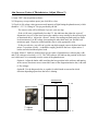
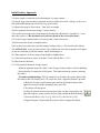
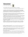
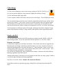
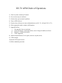
Park XE-70 AFM User Manual
Ed Fei and Ryan Brock
Updated 10/30/13
NOTE: This document is intended as a quick reference for basic operation of the
Park XE-70 and is by no means a comprehensive manual. It is strongly suggested
that users look through the Park documentation. The better you understand the
instrument, the more effectively you will be able to use it.
Basic AFM Principles
When the tip is suspended in air, the laser will hit the center of the quadrant photodetector.
If the tip encounters a feature on the surface, the tip deflects and the laser will move on the
quadrant photodetector. This is relayed to a motor controlling the tip which adjusts the tip’s
vertical position until the laser is aimed in the center of the quadrant photodetector once again.
Effectively, this keeps the tip at a constant distance from the sample surface. By recording the
position of the motor height, we can now know the topography of the sample surface.
The tips provided in this lab are intended for ‘non-contact’ AFM, which is similar in principle to
what is described above. Rather than relying on physical contact with the surface, the
cantilever/tip is oscillated at a given frequency above the sample surface, and interactive forces
from the surface lead to changes in the amplitude/phase of this oscillation.
Setting up the AFM is simple: adjust the mirrors until the light path follows the diagram below
Login To Badger, Enable Device
Hardware Setup
1) Unplug head and remove it by pulling flaps towards you and sliding head out to the right.
Never handle head from bottom to ensure safety of the AFM tip.
2) Mount sample on stage
3) Mount a new tip if one is not already mounted. If using your own tips, CAREFULLY remove
the existing tip and place it in the ‘good’ tips box. Ensure new tip is rested in place and that
bearings fit into tip slots.
4) Replace head and push flaps away from you until slightly tight. This secures the head
position. Plug head in.
5) Check that SPM Controller and Monitors are On (should already be on)
6) Turn on Light Bank and Laser (via “Laser Switch”). LEDs on head indicate general location
of laser on photodetector.
7) Open ‘uEye Demo’, click on Open USB Camera (icon in top left corner). Drag window to
right hand monitor.
Flaps
Laser switch
Plug
Head
Aim Laser on End of Cantilever (Adjust Mirror 1)
y
x
Mirror 1
Mirror 2
Find and focus on cantilever: If you don’t see the cantilever right away, first check that the
optical microscope is focused at the proper height to see the cantilever and check that enough
light is coming from the light bank. If you still don’t see the cantilever, you will need to adjust
the position of the microscope (knobs located above head on microscope column). Look at
where the light from the microscope is shining on the tip assembly, as this will help you to center
the microscope.
Position laser on cantilever: If you don’t see the laser reflected off the cantilever (and the laser
is on), use the ‘Mirror 1’ knobs to move the laser along the vertical axis until you see it reflected
on the edge of the probe, then move horizontally as needed. Tightening the vertical position
knob will raise the laser, loosening it will lower it. Aim the laser near the end of the cantilever
(example above), where the deflection will be the greatest.
NOTE: Make sure that you position the primary beam spot - you may also see a reflected laser
spot that will be dimmer. To make sure you are aiming the primary beam spot on the end of the
cantilever, move the laser to the base of the cantilever then loosen the vertical position knob.
This will lower the laser position to the end of the cantilever.
Aim Laser on Center of Photodetector (Adjust Mirror 2)
1) Open ‘XEP’ data acquisition software
2) If frequency sweep window opens, just click OK to close.
3) Check (A+B) voltage value (measures total intensity of light hitting the photodetector), which
should be ~2.5-3 V if using ACTA tips provided by the lab.
- The correct value will be different if you use your own tips.
- If the (A+B) sum is significantly less than 3V, this indicates that either the ‘mirror 2’
alignment is way off, or the laser spot on the cantilever may actually be the reflected spot
as mentioned above. Adjust the ‘mirror 2’ knobs, first turning one knob until you find a
local maximum of (A+B) voltage, then turning the other knob until you find the local
maximum again. Repeat as needed until the sum is at the appropriate value.
- If after several tries, you still can’t get the sum high enough, remove the head and check
mirror 2’s position visually – it should be roughly parallel to the base. Adjust mirror 2
knobs as needed and then replace head
4) Adjust ‘Mirror 2’ knobs to position laser spot on center of photodetector, reducing the (A-B)
and (C-D) voltages to less than +/-0.3V. The XEP software will indicate the position of the laser
as a red dot once it is reasonably near the center of the photodetector.
Option A: Adjust the knobs while watching the laser position in the software and turning
in the correct direction to move toward the center of the diagram/minimize the (A-B) and
(C-D) voltages.
Option B: Use the diagram below as a guide for which knob to turn and in which
direction depending upon where the laser is shining.
Photodetector
L1, L2
L2
T1, L2
Mirror 2 Knobs
11
2
2
L1
T1
T = tighten
L = loosen
T2,L1
T2
T2, T1
Mode, Scanner, and Frequency Selection
1) Turn off Head in software
2) Click on Parts Select
3) Select proper mode of operation and scanner ranges
Head Mode: NC-AFM - ACTA tips should only be used for NC-AFM (non-contact mode)
XY Voltage Mode: High (50um x 50um) or Low (5umx5um)
Z Voltage Mode: High (12 um) or Low (1.7 um)
Z Scanner Range: Set to 1.00
Cantilever: General
4) Click OK
5) Turn Head back on in software, Frequency Sweep Window will open.
6) The software will automatically detect the cantilever’s resonance peak and select a driving
frequency just above that peak.
- If a very weak peak appears (peak is on the order of the noise) or if there is strong nonideal behavior like a double peak, replace the tip. An additional indication of a bad
cantilever is a Drive % at/near 100. This is a rare occurrence under normal operation.
7) Click OK
Bad (low amplitude, 100% drive)
Good
Initial Surface Approach
1) Ensure sample is under the tip by adjusting the x/y stage controls.
2) Using Z-stage control window, approach surface to within a few mm. Only go as far as you
feel comfortable that the tip is still well away from surface.
3) Adjust microscope to focus on tip. Then focus on sample.
4) Move sample to desired area using x/y stage controls
5) Focus the microscope away from sample by turning fine adjust knob ¼ turn (this is ~1 mm
above the surface). **Be absolutely sure you have moved in the correct direction**
6) Use the Z-stage control window to lower tip until it comes into focus.
7) Refocus the microscope on sample surface
8) Focus the microscope away just until sample is blurry (this is ~ 100 um above the surface)
9) CAUTIOUSLY, lower tip until in focus. Be careful not to lower the tip past the focal plane
as you may crash the tip into the sample, which could damage it.
10) When sample is in focus, image of tip should be slightly blurry
11) Check laser position to ensure A-B and C-D are still less than +/- 0.3 V
12) Shut acoustic enclosure
13) Click Approach button in Z-stage control
- When the approach stops, the “light” in the Z-stage Control window will stop blinking.
- Ensure that the Z-scanner bar is half green. This indicates that the system is tracking
the surface.
- Z-scanner troubleshooting: If the Z-scanner bar is all white, the system did not find
the surface (and will actually move UP, not down, if the ‘Approach’ button is pressed).
1) Raise the Z-stage a small amount (just until the tip becomes blurry in the
optical microscope and the topography trace goes flat)
2) Z-scanner will turn green
2a) If the Z-scanner bar does not turn green after you have retracted the tip,
open the frequency sweep window (icon at right) and hit the Refresh button.
3) Increase the Drive % by 5% (e.g. 10% to 15%, not 10% to 10.5%)
4) Approach again. Repeat until the system is able to engage the sample.
Optimize Scan Parameters
1) Click on Input configuration icon
2) Select channels of interest, show at least trace and retrace of topography
3) Change the scan size to appropriate value (5µm or 50µm max depending on XY scanner)
A good image is achieved when trace and retrace show the same topography and are stable
(repeatedly show the same topography and there are no random spikes or other instabilities).
Trace and retrace may not overlap perfectly but if the shapes of the curves are identical, then the
image will generally be good. To improve the tracking, adjust the following:
4) Z-servo gain - Increasing the gain will help the tip track the sample better. However, if the
gain is too high, you will see high-frequency noise. Increase/decrease the gain until the best
image is obtained. In most cases, the optimal value will be from 1-5.
5) Scan rate - Decrease the scan rate to 0.5 Hz or 0.25 Hz. This effectively reduces the speed at
which the tip moves, allowing the system more time to adjust to sudden changes in height. Be
careful, as this will also proportionately increase the time needed to take images.
6) Set Point - Adjusting the Set Point up/down will change the distance the tip hovers above the
sample surface when scanning and can improve resolution of features/surface tracking. This can
be done manually by changing the number in the ‘Set Point’ box or by adjusting the red bar in
the frequency sweep window.
7) Drive % - Adjust the Drive% by a few tenths of a percent at a time to see if your image
quality improves. This will increase the force with which the tip oscillates. Only adjust this
setting after exhausting the other options as increasing the drive can deteriorate the tip life.
Getting a good image can take time. It is a matter of iterating between adjusting the gain, set
point and drive. If you are unable to get a good image, there are three additional options:
1) Hit the “NCM ASetup” button at the bottom of the scan parameters window. This will run an
automatic routine to try and find a good set of scan parameters. The frequency window will
open automatically. Hit OK to close this window.
2) If you still don’t see your surface, retract the tip from the sample, increase the initial drive %,
and re-approach the sample.
3) If you still don’t see your surface, it may be that the tip you are using is damaged. Raise the
optical microscope, then raise the Z-stage well away from your surface. Remove the head. Put
the tip in the ‘Bad Probes” box and select a new probe from the ‘Good Probes’ box.
Collect Image
1) Click on Scan Parameters icon to select image resolution (128x128, 256x256, etc).
1a) You may need to adjust the scan parameters slightly after making a change.
2) Click Start button under Image label.
3) Once complete, double click on the color bars next to the images. This will flatten the image.
You can send the image to the Scan Area Control by right clicking on the image, and hit “Send
to Scan Area Control”. Click on the ‘Scan Area’ tab at the bottom of the scan control window.
This will allow you to shift your next scan area relative to the image you just collected, and
automatically adjusts the software settings to the appropriate scan size, x/y offsets, and rotation.
To take an image in a different region of the sample, disengage from surface using the Z-stage
control, adjust position with the x/y stage controls, and repeat the surface approach procedure.
Modify with XEI
You can send images directly to the XEI data analysis software from the ‘Buffer’ in XEP by
right clicking on them. Or you can open them from the ‘spmdata’ or ‘User Files’ folders.
Flattening your sample:
To flatten your sample, go to the flatten area button. Select all the areas that are supposed to be
flat and on the same height. Exclude any non-flat features (e.g. mesas, trenches etc) that will
distort the flattening routine. Select the line routine (1st order regression). Select x-axis if your
scan was done in the x-axis, y-axis if your scan was done in the y-axis. Click “Execute”. Save
your flattened image (preferably as a separate file).
You can also try using the line, whole, and difference routines. Read more about the different
flattening algorithms in the XEI manual.
Another useful feature is the ability to save the numerical data from any image, graph, or table as
a .txt file by right clicking on the image/graph/table.
Save file to ‘User Files’ folder. Include .tiff extension in filename.
Screenshots can also be exported as jpg, png, of bmp files by selecting Export from the File
menu.
Shut down
CAUTION: ENSURE HEAD WILL NOT CONTACT MICROSCOPE!!
1) DO NOT hit “Lift Z” right away. The stage will hit the microscope on the way up and
damage one or both of them. Use Z-stage control to lift tip away from sample a small distance so
the tip is no longer touching the sample.
2) Open the acoustic enclosure
3) Raise microscope to full height
4) Hit ‘Lift Z’ button in Z-stage control
5) Refocus microscope on cantilever
6) Turn off laser switch, unplug head, and remove head.
6a) If the tip you used was good, leave it on the AFM. Otherwise, remove head and place tip in
the “Bad Probes” box
7) Remove sample from stage and replace head, plug head in.
8) Close XEP/XEI software
9) Turn off Light Bank
10) Leave the SPM Controller on
**Log tip usage, clean up after yourself, and disable in Badger**
Note: We recycle used sample pucks and also used tips. Please put used items in the proper
places. Do not throw them in the trash.
If you notice any problems while running the instrument, please make a comment on Badger and
email the lab managers at [email protected].
XE-70 AFM Order of Operations
1) Turn on system, mount tip if needed
2) Focus microscope on cantilever
3) Position laser spot on end of cantilever
4) Turn on XEP software
5) Position laser reflection on center of photodetector (A+B ~3V, A-B and C-D ~0.3V)
6) Select appropriate mode, scanner, and frequency
7) Approach surface
i.
ii.
iii.
iv.
Get optically close (several mm)
Focus microscope ~1mm from surface, move Z-stage til cantilever in focus
Repeat at ~100um from surface
Click ‘Approach’
8) Adjust scan parameters (Z servo gain, scan rate, set point, drive)
9) Collect images
10) Send to XEI to process/save
11) Follow shutdown procedure