1
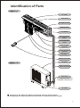
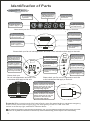
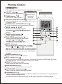
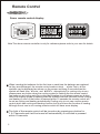
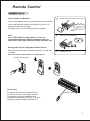
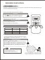
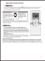
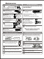
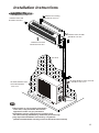
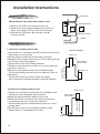
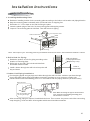
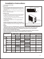
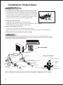
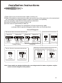
Installation Instructions
Front panel
Connecting of the Cable
Wiring between the indoor and outdoor units:
Terminal (inside)
1) Remove the PCB cover from the indoor unit;
2) Refer to the wiring diagram attached to indoor unit
when connecting cords to indoor unit terminals;
3) Reinstall the PCB cover. Be sure that side B
is facing outside.
COVER
COVER
A side (before connect)
B side (after connect)
Cabinet
Select the best location
Location for Installing Indoor Unit
Installation Diagram
Indoor unit
Pipe length is
49 feet Max.
Height should
be less than 16 ft
Where there is no obstacle near the air outlet and air can be
easily blown to every corner.
Where piping and wall hole can be easily arranged.
Keep the required space from the unit to the ceiling and wall
according to the wiring diagram.
Where the air filter can be easily removed.
Keep the unit and remote controller 1m or more apart from
television, radio etc.
Keep as far as possible away from fluorescent lamps.
Do not put anything near the air inlet to obstruct it from air
absorption.
Where there is strong enough to bear the weight
and is not tend to increase operation noise and vibration.
Location for Installing Outdoor Unit
Outdoor unit
Pipe length is
49 feet Max.
Height should
be less than 16 ft
Where it is convenient to install and well ventilated; avoid
installing it where flammable gas could leak.
Keep the required distance apart from the wall.
Keep the outdoor unit away from a place of greasy dirt,
vulcanization gas exit or high salty seashore.
Avoid installing it at the roadside where there is a risk of
muddy water.
A fixed base so as not to increasing operation noise.
Where there is no blockage for air outlet.
Indoor unit
13
Outdoor unit