1
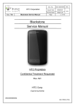
EN
technical manual
10006491_12
TABLE OF CONTENTS
1
2
GENERAL & TECHNICAL DATA .......................................................... 1
1.1
Warnings and cautions ................................................................................................................ 1
1.2
Manual versions ........................................................................................................................... 2
1.3
Technical specifications ............................................................................................................... 3
1.4
User’s statement for Planmeca Intra ........................................................................................... 5
1.5
EMC information .......................................................................................................................... 8
SERVICE MODE ................................................................................... 12
2.1
Control panel ............................................................................................................................. 12
2.2
How to enter/exit the service mode ........................................................................................... 12
2.3
X-ray tube filament preheating voltage calibration ..................................................................... 13
2.4
kV range selection ..................................................................................................................... 13
2.5
Operation of the preprogrammed settings keys (kV hold) ......................................................... 14
2.6
Dimming the displays ................................................................................................................. 15
2.7
Duration of the displays dimming time-out ................................................................................. 16
2.8
Disabling the exposure key ........................................................................................................ 17
2.9
Automatic identification of the cascade card ............................................................................. 18
2.10 Specifying the PCB versions ..................................................................................................... 18
2.11 Ready-state setting .................................................................................................................... 19
3
RECALLING THE FACTORY PREPROGRAMMED EXPOSURE
VALUES ................................................................................................ 20
4
TROUBLESHOOTING .......................................................................... 21
5
ERROR MESSAGES ............................................................................ 22
6
7
8
5.1
Error message shortform table .................................................................................................. 22
5.2
Detailed error message explanations ........................................................................................ 23
MECHANICAL ADJUSTMENTS .......................................................... 28
6.1
Adjusting the balance of the arm ............................................................................................... 28
6.2
Adjusting the bracket arm angles .............................................................................................. 29
6.3
Adjusting the stiffness of the tube head’s horizontal axle .......................................................... 30
6.4
Vertical tube head stiffness adjustment screw ........................................................................... 31
PARTS REPLACEMENT & REPAIR .................................................... 32
7.1
Replacing the Generator PCB ................................................................................................... 32
7.2
Replacing the tube head PCB ................................................................................................... 35
7.3
Replacing the tube head ............................................................................................................ 36
7.4
Replacing the arm cables .......................................................................................................... 37
7.5
Replacing the control panel cable .............................................................................................. 44
DIAGRAMS ........................................................................................... 45
COPYRIGHT PLANMECA 2007-10
PUBLICATION NUMBER 10006491 revision 12
Technical manual
Planmeca Intra x-ray unit TOC-1
GENERAL & TECHNICAL DATA
1
GENERAL & TECHNICAL DATA
1.1
Warnings and cautions
WARNING
THE FOLLOWING WARNINGS, CAUTIONS AND NOTES MUST
ALWAYS BE CONSIDERED WHILE SERVICING THE UNIT, IN ORDER
TO AVOID EITHER PERSONAL INJURY OR DAMAGE TO THE UNIT.
CAUTION
RADIATION SAFETY RULES
Some procedures described in this manual produces X-ray radiation.
Always follow the rules for radiation protection.
Never attempt to open the tube head. It does not contain any
serviceable parts, and radiation safety could not be guaranteed any
more.
CAUTION
ELECTRICAL SAFETY RULES
The unit contains hazardous voltages. While servicing internal parts,
always turn off externally the power to the unit, and wait for 2 minutes
before touching any electrical parts.
Always replace the fuses with ones of the same type and rating.
Otherwise patient, operator or equipment safety cannot be
guaranteed.
The circuit boards can be damaged due to static discharges and
require careful handling.
CAUTION
GENERAL SAFETY RULES
The unit must be serviced only by qualified personnel, trained by
PLANMECA. Repairs and parts replaced by unqualified personnel
carry no warranty.
Periodical maintenance as described in this manual must be
performed on a regular basis, to ensure the safety and image quality
of the unit.
Some procedures described in the unit could be dangerous, if not
followed as stated.
Technical manual
Planmeca Intra x-ray unit 1
GENERAL & TECHNICAL DATA
CAUTION
Check that the X-ray unit is installed properly and no mechanical play
caused by wear, corrosion, metal fatigue or ageing can be found
between the wall bracket and horzontal arm.
1.2
Manual versions
Planmeca pursues a policy of continual product development. Although every effort is made
to produce up-to-date product documentation this publication should not be regarded as an
infallible guide to current specifications. We reserve the right to make changes without prior
notice.
NOTE
2 Planmeca Intra x-ray unit
This manual is only valid for the software versions from 3.01 and
later.
Technical manual
GENERAL & TECHNICAL DATA
1.3
Technical manual
Technical specifications
Generator
Constant potential, microprocessor controlled,
operating frequency 66 kHz
X-ray tube
Toshiba D-0711SB
Focal spot size
0.7 mm according to IEC 60336
Cone diameter
60 mm (2.36 in.)
Rectangular 33 x 43 mm (1.30 x 1.69 in.)
Max. symmetrical radiation field
ø 60 mm at SSD 200 mm
ø 60 mm at SSD 300 mm
according to IEC 806
Total filtration
min. 2 mm Al equivalent at 70 kV
according to IEC 60522
Inherent filtration
1 mm Al equivalent at 70 kV
according to IEC 60522
Anode voltage
50, 52, 55, 57, 60, 63, 66, 70 kV, ±2 kV
Anode current
8, 7, 6, 5, 4, 3, 2 mA ±(5% + 0.2 mA)
Target angle
16°
Exposure times
0.01-3.2 sec. ±(5% + 0.001 sec.), 26 steps
Reference current time product
8 mAs at 70 kV, 8 mA, 1 sec.
Lowest current time product
0.02 mAs at 2 mA, 0.01 sec.
Max. nominal anode voltage
70 kV
Max. electrical output
560 W at 70 kV, 8 mA
Electrical output at 0.1 sec.
560 W at 70 kV, 8 mA
Max. loading energy
1800 mAs/h at 70 kV
SSD (Source-Skin Distance)
Standard/Long
Long with rectangular collimator
200 mm (8 in.)/300 mm (12 in.)
306 mm (12.04 in.)
Mains voltage
100 V~/110-115 V~/220-240 V~
Apparent resistance
0.3 ohms 110-115 V~ /
0.8 ohms 220-240 V~
Mains frequency
50/60 Hz
Fusing
8 AT 250 VAC at 220-240V~
15 AT 250 VAC at 100 V~/110-115 V~
Duty cycle
1:15, automatic control
Electrical classification
Class I
Type B
Planmeca Intra x-ray unit 3
GENERAL & TECHNICAL DATA
Mechanical data
Weight
total 23 kg (51 lbs)
tube head 4.2 kg (9.3 lbs) with standard cone
4.5 kg (10 lbs) with long cone
Color
RAL 9016
Environmental requirements
Ambient temperature
operating +5°C - +40°C storage -10°C - +50°C
Humidity
25% - 75%
External mains fuse recommendation
The recommendation for the external mains fuses are:
•
units with 100V~ or 115V~ voltage setting:
16A, time lag
•
units with 220-240V~ voltage setting:
10A, time lag
No other equipment should be connected to the same fused mains line as the x-ray unit. In
some countries an additional external fault current guard is also required.
Original manufacturer
PLANMECA Oy, Asentajankatu 6, FIN-00880, Helsinki, FINLAND
phone: +358-20-7795 500
4 Planmeca Intra x-ray unit
Technical manual
GENERAL & TECHNICAL DATA
1.4
User’s statement for Planmeca Intra
Radiation leakage technique factors
The maximum rated peak tube potential is 70 kV and the maximum rated continuous tube
current is 0.53 mA for the maximum rated peak tube potential.
Minimum filtration
The radiation port contains an added 1.0 mm aluminium filtration. The measured half-value is
0.50 - 0.55 at 70 kV. The measured value corresponds to an aluminium equivalent of 2.0 mm.
Rated line voltage
100, 110-117, 220-240 V~ ±10%. Line voltage regulation 10%.
Maximum line current
6.1 A at 230 V~, 12.2 A at 115 V~
Technique factors that constitute the maximum line current condition
70 kV, 8 mA
Generator rating and duty cycle
1.4 kW, duty cycle 1:15. The wait period is controlled automatically by calculating it according
to the formula tw = 15 x texp.
Maximum deviation of peak tube potential from indicated value
± 2.0 kV
Maximum deviation of tube current from indicated value
±10%
Maximum deviation of exposure time from indicated value
±10%
DEFINITION OF MEASUREMENT CRITERIA
Exposure time
The beginning and end points of the exposure time are defined at 70% of the peak radiation
waveform measured with a calibrated x-ray monitor.
Peak tube potential
Is defined as the high voltage mean value measured with a calibrated non-invasive kVp
meter.
Tube current
Is defined using the voltage over the feedback resistor measured with a calibrated multimeter.
The mA value is calculated by dividing the voltage by the resistance value.
Technical manual
Planmeca Intra x-ray unit 5
GENERAL & TECHNICAL DATA
The nominal x-ray voltage together with the highest x-ray tube current
obtainable from the high-voltage generator when operated at it’s highest xray tube voltage
70 kV, 8 mA
The nominal x-ray tube current when operated at the highest x-ray tube
voltage
8 mA, 70 kV
The x-ray tube voltage and tube current which result in the highest electric
output power
70 kV, 8 mA
The nominal electric power for a load time of 0.1 sec and at the nominal xray tube voltage
1.4 kW at 70 kV, 8 mA
Anode heating/cooling curve of the X-ray tube
6 Planmeca Intra x-ray unit
Technical manual
GENERAL & TECHNICAL DATA
X-ray tube assembly heating/cooling curve
X-ray tube assem bly heating/cooling curve
140
18 W
120
13 W
Heat Storage (kJ)
100
80
60
40
Cooling
20
0
0
30
60
90
120
150
180
210
240
270
300
Tim e (m in)
Technical manual
Planmeca Intra x-ray unit 7
GENERAL & TECHNICAL DATA
1.5
EMC information
WARNING
Use of any accessories and cables other than those specified in
Planmeca Intra X-ray unit’s documentation, with exception of cables
sold by Planmeca as replacement parts for internal components, may
result in increased emission or decreased immunity of the X-ray unit.
WARNING
Planmeca Intra X-ray unit should not be used adjacent to or stacked
with other equipment. If adjacent or stacked use is necessary, the
Planmeca Intra X-ray unit should be observed to verify normal
operation in configuration which it will be used.
Guidance and manufacturer’s declaration - electromagnetic emissions
Planmeca Intra X-ray unit is intended for use in the electromagnetic environment specified
below. The customer or the user of the Planmeca Intra X-ray unit should assure that it is used in
such an environment.
Emissions test
Compliance
Electromagnetic environment – guidance
Group 1
Planmeca Intra X-ray unit uses RF energy only
for its internal function. Therefore, its RF emissions are very low and are not likely to cause any
interference in nearby electronic equipment.
RF emissions
CISPR 11
RF emissions
Class B
CISPR 11
Harmonic emissions
Planmeca Intra X-ray unit is suitable for use in all
establishments, including domestic establishments and those directly connected to the public
low-voltage power supply network that supplies
buildings used for domestic purposes.
Class A
IEC 61000-3-2
Voltage fluctuations/
flicker emissions
Complies
IEC 61000-3-3
8 Planmeca Intra x-ray unit
Technical manual
GENERAL & TECHNICAL DATA
Guidance and manufacturer’s declaration - electromagnetic immunity
Planmeca Intra X-ray unit is intended for use in the electromagnetic environment specified below. The customer or the user of Planmeca Intra X-ray unit should assure that it is used in such an environment.
IEC 60601
test level
Immunity test
Electrostatic
discharge (ESD)
Compliance level
±6 kV contact
±6 kV contact
±8 kV air
±8 kV air
Electrical fast
transient/burst
±2 kV for power
supply lines
±2 kV for power
supply lines
IEC 61000-4-4
±1 kV for input/output
lines
±1 kV for input/output
lines
Surge
±1 kV line to line
±1 kV line to line
IEC 61000-4-5
±2 kV line to earth
±2 kV line to earth
Voltage dips, short
interruptions and
voltage variations
on power supply
input lines
<5 % UT
(>95 % dip in UT)
for 0,5 cycle
<5 % UT
(>95 % dip in UT)
for 0,5 cycle
40 % UT
(60 % dip in UT)
for 5 cycles
40 % UT
(60 % dip in UT)
for 5 cycles
70 % UT
(30 % dip in UT)
for 25 cycles
70 % UT
(30 % dip in UT)
for 25 cycles
<5 % UT
(>95 % dip in UT)
for 5 s
<5 % UT
(>95 % dip in UT)
for 5 s
3 A/m
3 A/m
IEC 61000-4-2
IEC 61000-4-11
Power frequency(
50/60 Hz)
magnetic field
IEC 61000-4-8
Electromagnetic environmentguidance
Floors should be wood, concrete
or ceramic tile. If floors are covered with synthetic material, the
relative humidity should be at
least 30%.
Mains power quality should be
that of a typical commercial or
hospital environment
Mains power quality should be
that of a typical commercial or
hospital environment.
Mains power quality should be
that of a typical commercial or
hospital environment. If the user
of Planmeca Intra X-ray unit
requires continued operation during power mains interruptions, it
is recommended that Planmeca
Intra X-ray unit be powered from
an uninterruptible power supply.
Power frequency magnetic fields
should be at levels characteristic
of a typical location in a typical
commercial or hospital environment. The power frequency magnetic field should be measured in
the intended installation location
to assure that it is sufficiently low.
NOTE UT is the a.c. mains voltage prior to application of the test level.
Technical manual
Planmeca Intra x-ray unit 9
GENERAL & TECHNICAL DATA
Guidance and manufacturer’s declaration - electromagnetic immunity
Planmeca Intra X-ray unit is intended for use in the electromagnetic environment specified below. The
customer or the user of Planmeca Intra X-ray unit should assure that it is used in such an environment.
IEC 60601
test level
Immunity test
Compliance
level
Electromagnetic environmentguidance
Portable and mobile RF communications
equipment should be used no closer to any
part of the Planmeca Intra X-ray unit, including cables, than the recommended separation distance calculated from the equation
applicable to the frequency of the transmitter.
Recommended separation distance
Conducted RF
3 Vrms
IEC 61000-4-6
150 kHz to 80 MHz
Radiated RF
3 V/m
IEC 61000-4-3
80 MHz to 2.5 GHz
3 Vrms
3 V/m
d = 1.2 P
d = 1.2 P
80 MHz to 800 MHz
d = 2.3 P
800 MHz to 2.5 GHz
where P is the maximum output power rating of the transmitter in watts (W) according
to the transmitter manufacturer and d is the
recommended separation distance in
metres (m).
Field strengths from fixed RF transmitters,
as determined by an electromagnetic site
survey,a should be less than the compliance
level in each frequency range.b
Interference may occur in the vicinity of
equipment marked with the following symbol:
NOTE 1: At 80 MHz and 800 MHz, the higher frequency range applies.
NOTE 2: These guidelines may not apply in all situations. Electromagnetic propagation is affected by
absorption and reflection from structures, objects and people.
a
Field strengths from fixed transmitters, such as base stations for radio (cellular/cordless)
telephones and land mobile radios, amateur radio, AM and FM radio broadcast and TV broadcast
cannot be predicted theoretically with accuracy. To assess the electromagnetic environment due
to fixed RF transmitters, an electromagnetic site survey should be considered. If the measured
field strength in the location in which Planmeca Intra X-ray unit is used exceeds the
applicable RF compliance level above, Planmeca Intra X-ray unit should be observed to
verify normal operation. If abnormal performance is observed, additional measures may be
necessary, such as re-orienting or relocating Planmeca Intra X-ray unit.
b
Over the frequency range 150 kHz to 80 MHz, field strengths should be less than 3 V/m.
10 Planmeca Intra x-ray unit
Technical manual
GENERAL & TECHNICAL DATA
Recommended separation distances between
portable and mobile RF communications equipment and Planmeca Intra X-ray unit
Planmeca Intra X-ray unit is intended for use in an electromagnetic environment in which radiated RF disturbances are controlled. The customer or the user of Planmeca Intra X-ray unit can help prevent electromagnetic interference by maintaining a minimum distance between portable and mobile RF
communications equipment (transmitters) and the Planmeca Intra X-ray unit as recommended below,
according to the maximum output power of the communications equipment.
Rated maximum output power
of transmitter
Separation distance according to frequency of transmitter
m
150 kHz to 80 MHz
W
Technical manual
d = 1.2 P
80 MHz to 800 MHz 800 MHz to 2.5 GHz
d = 1.2 P
d = 2.3 P
0.01
0.2
0.2
0.3
0.1
0.4
0.4
0.7
1
1.2
1.2
2.4
10
4.0
4.0
8.0
100
12.0
12.0
24.0
Planmeca Intra x-ray unit 11
SERVICE MODE
2
2.1
SERVICE MODE
Control panel
Preprogrammed setting
keys and indicator lights
Adult/child selection key
and indicator light
Exposure warning
indicator light
Ready indicator light
Exposure key
kV display
66
Time display
8
mA display
0.250
Mode key
Select key
Parameter adjustment keys
2.2
How to enter/exit the service mode
Press and hold down the select key for 4 seconds.
Press and hold down the Mode key for more than 2 seconds, until the four uppermost preprogrammed setting indicator lights come on.
To exit from the service mode
Press the Mode key briefly.
12 Planmeca Intra x-ray unit
Technical manual
SERVICE MODE
2.3
X-ray tube filament preheating voltage calibration
Enter the service mode according to the instruction given in section 2.2 “How to enter/exit the
service mode” on page 12.
Press and hold down the adult/child mode selection key for 2 seconds or until the indicator
light starts to blink. The indicator lights will start to blink indicating that you are in the preheating voltage calibration mode.
Move as far away from the x-ray tube as the length of the cable from the control panel permits.
Press and hold the exposure key on the control panel until 16 exposures are performed
(approx. 30 seconds).
Press the Mode key briefly to exit the service mode.
2.4
kV range selection
Enter the service mode according to the instruction given in section 2.2 “How to enter/exit the
service mode” on page 12.
Press the parameter adjustment up key until the parameter number 14 appears on the kV display.
14
0
Parameter adjustment up -key
The code of the kV range (0 - 9) is shown on the time display. The kV ranges are: 0 = 50-70,
1 = 55-70, 2 = 60-70, 3 = 66-70, 4 = 70, 5 = 50-68, 6 = 55-68, 7 = 60-68, 8 = 66-68 and 9 = 68
kV.
Press the Select key until the kV range code starts to blink, and the range can now be
changed with the parameter adjustment keys.
Select key
Parameter adjustment keys
Accept the new kV range by pressing the Select key.
Press the Mode key briefly to exit the service mode.
Technical manual
Planmeca Intra x-ray unit 13
SERVICE MODE
2.5
Operation of the preprogrammed settings keys (kV hold)
Enter the service mode according to the instruction given in section 2.2 “How to enter/exit the
service mode” on page 12.
Press the parameter adjustment up key until the parameter number 15 appears on the kV display.
15
0
Parameter adjustment up -key
The number indicating the operation of preprogrammed settings keys (0 or 1) is shown on the
time display.
0: Normal operation (factory setting). The preprogrammed settings keys operate as described
in the Planmeca Intra user’s manual.
1: kV hold. The selection of a preprogrammed setting does not affect the prior manually
inserted kV value, but the exposure time is recalculated to achieve constant optical density on
the film. In the case the kV value is now manually altered, the exposure time will also be
changed automatically. If the exposure time is manually altered, the unit will return into manual mode. At any time, the preprogrammed setting for the kV value, mA value and exposure
time for any tooth position is called by selecting the preprogrammed setting and pressing the
child mode selection key twice.
Press and hold down the Select key until the number starts to blink, and the number can now
be changed with the parameter adjustment keys.
Select key
Parameter adjustment keys
Accept the new setting by pressing the Select key.
Press the Mode key briefly to exit the service mode.
14 Planmeca Intra x-ray unit
Technical manual
SERVICE MODE
2.6
Dimming the displays
Enter the service mode according to the instruction given in section 2.2 “How to enter/exit the
service mode” on page 12.
Press the parameter adjustment up key until the parameter number 16 appears on the kV display.
16
0
Parameter adjustment up -key
The number indicating the brightness of the displays (from 1 to 5, factory default is 5) is
shown on the time display.
Press the Select key until the number starts to blink, and the value can now be changed with
the parameter adjustment keys.
Select key
Parameter adjustment keys
Accept the new setting by pressing the Select key.
Press the Mode key briefly to exit the service mode.
Technical manual
Planmeca Intra x-ray unit 15
SERVICE MODE
2.7
Duration of the displays dimming time-out
Enter the service mode according to the instruction given in section 2.2 “How to enter/exit the
service mode” on page 12.
Press the parameter adjustment up key until the parameter number 17 appears on the kV display.
17
0
Parameter adjustment up -key
The number indicating the time-out value (0, 1, 2, 3, 4, 5) is shown on the time display. The
time-out values are: 0 = no dimming, 1 = 1 min., 2 = 2 min., 3 = 5 min., 4 = 20 min. and 5 = 60
min. Factory default is 1.
Press the Select key until the number starts to blink, and the value can now be changed with
the parameter adjustment keys.
Select key
Parameter adjustment keys
Accept the new setting by pressing the Select key.
Press the Mode key briefly to exit the service mode.
16 Planmeca Intra x-ray unit
Technical manual
SERVICE MODE
2.8
Disabling the exposure key
Enter the service mode according to the instruction given in section 2.2 “How to enter/exit the
service mode” on page 12.
Press the parameter adjustment up key until the parameter number 18 appears on the kV display.
18
0
Parameter adjustment up -key
The number indicating the mode of exposure key operation is shown on the time display. 0 =
exposure key normal operation, 1 = exposure key operation disabled. The factory default is 0.
Press the Select key until the number starts to blink, and the value can now be changed with
the parameter adjustment keys.
Select key
Parameter adjustment keys
Accept the new setting by pressing the Select key.
Press the Mode key briefly to exit the service mode.
Technical manual
Planmeca Intra x-ray unit 17
SERVICE MODE
2.9
Automatic identification of the cascade card
Enter the service mode according to the instruction given in section 2.2 “How to enter/exit the
service mode” on page 12.
Press the parameter adjustment up key until the parameter number 19 appears on the kV display.
19
108
Parameter adjustment up -key
The value indicating the type of the cascade card is shown on the time display. Value < 108
equals an old card and value ≥ 108 equals a new card. The type of the cascade card affects
the adjustment functionality of the preheat and mA.
2.10 Specifying the PCB versions
Enter the service mode according to the instruction given in section 2.2 “How to enter/exit the
service mode” on page 12.
Press the parameter adjustment up key until the parameter number 20 appears on the kV display.
20
3
Parameter adjustment up -key
The value indicating the type of the PCB versions is shown on the time display. 1 = CPU PCB
version C3 (or older) with older cascade PCB, 2 = CPU PCB version C5 with newer cascade
PCB and 3 = CPU PCB version E1, works with both old and new cascade PCB. The factory
default is 3.
Press the Select key until the number starts to blink, and the value can now be changed with
the parameter adjustment keys.
Select key
Parameter adjustment keys
Accept the new setting by pressing the Select key.
Press the Mode key briefly to exit the service mode.
18 Planmeca Intra x-ray unit
Technical manual
SERVICE MODE
2.11 Ready-state setting
The Planmeca Intra X-ray unit can be set so that the Ready indicator light will only come on
when the Dimaxis program is ready for the exposure, i.e. the Waiting for exposure message is
on the computer screen.
Enter the service mode according to the instruction given in section 2.2 “How to enter/exit the
service mode” on page 12.
Press the parameter adjustment up key until the parameter number 21 appears on the kV display.
21
0
Parameter adjustment up -key
The number indicating the ready-state setting (0 or 1) is shown on the time display.
0: Normal operation (factory setting). The Planmeca Intra X-ray unit will go into Ready-state
regardless of PC operation.
1: The Ready indicator light will only come on when the Dimaxis program is ready for the
exposure
Press and hold down the Select key until the number starts to blink, and the number can now
be changed with the parameter adjustment keys.
Select key
Parameter adjustment keys
Accept the new setting by pressing the Select key.
Press the Mode key briefly to exit the service mode.
Technical manual
Planmeca Intra x-ray unit 19
RECALLING THE FACTORY PREPROGRAMMED EXPOSURE VALUES
3
RECALLING THE FACTORY PREPROGRAMMED
EXPOSURE VALUES
The factory preprogrammed exposure values are in the Planmeca Intra user’s manual, section 9 “EXPOSURE VALUES”.
Press and hold down any of the preprogrammed setting keys when switching the unit on. The
error code E.29 will appear on the time display.
E.29
Do not clear the error code by pressing the select key, but press the Occlusal exposure key
for 6 seconds. The factory preprogrammed values and density value 0 will be stored into
memory.
Press this key
20 Planmeca Intra x-ray unit
Technical manual
TROUBLESHOOTING
4
TROUBLESHOOTING
The control panel displays do not come on and the indicator light of
generator box is not on
Problems in mains voltage, or a fuse is blown.
Check the mains voltage. Check the mains cable. Check and replace, if necessary, the fuses
located on the lower left side of the generator box. Open the generator box and check and
replace, if necessary, the generator fuse F2. Replace the generator. (Perform the checks and
parts replacements in this order).
The control panel displays do not come on and the indicator light of
generator box is on
Control panel power failure, or the control panel is defective. The control panel operates with
12 V produced on the generator low voltage supply.
Check the control panel cable and the telephone cable. Replace the control panel. (Perform
the checks and parts replacements in this order).
Temperature of the tube head too high
61 C
Technical manual
If the temperature of the tube head exceeds 60 °C, the temperature will appear on the time
display. The control panel does not operate. Wait until the temperature drops.
Planmeca Intra x-ray unit 21
ERROR MESSAGES
5
E.11
ERROR MESSAGES
The error code is displayed on the time display.
Press the select key to clear the error from the display.
5.1
Error message shortform table
ERROR CODE
ERROR MESSAGE EXPLANATION
E.00
Exposure key was released too early during the exposure.
E.10
X-ray tube Anode voltage (kV) overshoot.
E.11
X-ray tube Anode voltage (kV) dropped suddenly.
E.12
X-ray tube cathode filament preheating voltages are not calibrated.
E.13
Filament preheating voltage calibration failed.
E.29
Membrane keyboard key short-circuited/pressed during the self test or faulty
display board.
E.30
kV value does not reach or it exceeds the given value (difference more than
5%).
E.31
X-ray tube Anode current (mA) missing, or not in specified limits.
E.33
X-ray tube Filament voltage (V) missing, or outside the range (too low or too
high).
E.34
X-ray tube Anode voltage (kV) missing, or below the specified limit.
E.36
Too long exposure.
E.37
kV feedback signal open circuit or short circuit.
E.38
mA feedback signal open circuit or short circuit.
E.50
Tube head temperature sensor short circuit.
E.51
Tube head temperature sensor open circuit.
E.52
Filament voltage feedback not in specified limits
E.57
Exposure key pressed during self test.
E.60
± 15VDC voltage is out of limits
E.61
Communication error between control panel and tube head CPU.
22 Planmeca Intra x-ray unit
Technical manual
ERROR MESSAGES
ERROR CODE
5.2
ERROR MESSAGE EXPLANATION
E.71
FLASH memory check-sum error (tube head CPU).
E.81
EEPROM memory defective (tube head CPU).
E.83
Config register error (tube head CPU).
Detailed error message explanations
E.00 Exposure key was released too early during exposure
The most probable cause (if the key really was pressed firmly during the whole exposure) is
faulty control panel or faulty separate exposure switch.
Replace the control panel or the separate exposure switch. Check the control panel cable, telephone cable and the arm cable.
E.10 X-ray tube anode voltage (kV) overshoot
This condition is monitored by the watch-dog circuit on the tube head PCB during the whole
exposure and if the anode voltage rises above 95 kV the exposure is immediately aborted
and this error indicated. A knocking sound may be heard from the tube head at the same
time. This kind of arcing can occur now and then without any special reason, and should be
considered a normal phenomenon. If however the occurrence frequency becomes too high, it
could be an indication of a degrading tube head.
If this error occurs constantly it is probably caused by a faulty tube head or tube head PCB or
generator PCB (replace in this order). The possible reason is also faulty feedback cable (9
pole) in the tube head.
E.11 X-ray tube anode voltage (kV) dropped suddenly
The x-ray tube voltage suddenly drops, and a knocking sound is heard from the tube head at
the same time. The exposure is aborted and this error indicated. This phenomenon should be
considered quite normal if it doesn’t occur frequently. If the generator is damaged during the
exposure, or the arm/extension cable is broken, this error is indicated and during next exposure the error E.30 occurs.
If this error occurs constantly it is probably caused by a faulty tube head or tube head PCB or
generator PCB (replace in this order). The possible reason is also faulty feedback cable in the
tube head.
E.12 X-ray tube cathode filament preheating voltages are not calibrated
The tube head PCB has been replaced, but the X-ray tube cathode filament preheating voltages are not calibrated.
See paragraph 2.3 “X-ray tube filament preheating voltage calibration” on page 13 for details
how to perform the calibration.
Technical manual
Planmeca Intra x-ray unit 23
ERROR MESSAGES
E.13 Filament preheating voltage calibration failed
During preheat calibration the filament voltage is measured to be in specified limits. The filament circuit in the tube head or in the tube head PCB is faulty or the tube head is faulty.
Perform the calibration procedure again. If it fails, replace the tube head or tube head PCB (in
this order). The possible reason is also faulty feedback cable in the tube head.
E.29 Control panel key short-circuited/pressed during the self test
This error can occur only during the self-test. During the self test the unit checks that all keys
are open (normal state if not pressed). If a key is found to be in short circuit, this error is displayed. Because the control panel keys are arranged in a matrix, one key’s short could cause
the whole keyboard to operate erroneously, therefore this check is important.
Replace the control panel.
The factory predetermined settings are recalled and the density value is set to zero by pressing any of the keys during the self test. The error code E.29 appears on the time display, after
which the right-hand preprogrammed setting key must be pressed and held down for 6 seconds. See section 3 “RECALLING THE FACTORY PREPROGRAMMED EXPOSURE VALUES” on page 20.
E.30 kV value does not reach or it exceeds the given value (difference more
than 5%)
The tube voltage is sampled periodically (by the tube head CPU) and if the actual measured
kV-value differs more than ± 3 kV from the specified value this error is displayed. The tube
head, tube head PCB, generator PCB or arm/extension cable signals HV1, HV2 or KVC (see
wiring diagram) can be faulty. See also error E.11 and E.34.
Check the incoming mains voltage during the exposure. Check the arm/extension cable and
the tube head feedback cable. Replace the generator PCB, tube head PCB or tube head
(replace in this order).
E.31 X-ray tube anode current (mA) missing, or not in specified limits
The tube current is sampled periodically (by the tube head CPU) and if the actual measured
mA-value differs more that ± 2 mA from the specified value this error is displayed. The tube
head, tube head PCB or tube head feedback cable can be faulty.
Proceed with the filament definition, see paragraph 2.3 “X-ray tube filament preheating voltage calibration” on page 13 for details. If this does not help and the error occurs constantly
check the tube head feedback cable, replace the tube head PCB, or tube head (in this order).
E.33 X-ray tube filament voltage (V) missing, or outside the range (too low or
too high)
The tube filament voltage is sampled periodically (by the tube head CPU) and if the actual
measured filament voltage is not in the specified limits (1.0 - 4.5 V) then this error is displayed. The filament circuit in the tube head or on the tube head PCB can be faulty.
Check the tube head feedback cable. Replace the tube head PCB or the tube head (in this
order).
24 Planmeca Intra x-ray unit
Technical manual
ERROR MESSAGES
E.34 X-ray tube anode voltage (kV) missing, or below the specified limit
This error occurs in the beginning of the exposure, when the tube anode voltage does not
rise. The tube head, tube head PCB, generator PCB or arm/extension cable signals HV1,
HV2 or KVC (see wiring diagram) can be faulty. See also error E.11 and E.30.
Check the incoming mains voltage during the exposure. Check the arm/extension cable and
the tube head feedback cable. Replace the generator PCB, tube head PCB or tube head
(replace in this order).
E.36 Too long exposure
The control panel CPU monitors the exposure time by measuring the state of the exp-signal.
If, however, the tube head CPU continues the exposure more than the maximum exposure
time, then the control panel CPU terminates the exposure and this error occurs. This is a
safety procedure, that guarantees that the exposure is terminated under all conditions.
Replace the tube head PCB if this error occurs repeatedly.
E.37 kV feedback signal open circuit or short circuit
The kV feedback signal is monitored by the tube head CPU. The internal connection of the
tube head or tube head feedback cable is faulty.
Check the condition of the feedback cable, replace the tube head PCB or the tube head (in
this order).
E.38 mA feedback signal open circuit or short circuit
The mA feedback signal is monitored by the tube head CPU. The internal connection of the
tube head or tube head feedback cable is faulty.
Check the condition of the feedback cable, replace the tube head PCB or the tube head (in
this order).
E.50 Tube head temperature sensor short circuit
The tube head temperature sensor signal is measured by the tube head CPU. The sensor is
short-circuited, the tube head PCB or the tube head feedback cable is faulty.
Check the feedback cable. Replace the temperature sensor (beside the signal connectors of
the tube head), or the tube head PCB (in this order).
E.51 Tube head temperature sensor open circuit
The tube head temperature sensor signal is measured by the tube head CPU. The temperature sensor is damaged, the tube head PCB or the tube head feedback cable is faulty.
Check the feedback cable. Replace the tube head PCB.
E.52 Filament voltage feedback not in specified limits
The filament voltage is monitored by the tube head CPU. The amplifier is faulty.
Replace the tube head PCB.
Technical manual
Planmeca Intra x-ray unit 25
ERROR MESSAGES
E.57 Exposure key pressed/failure during self test
The tube head CPU checks the state of the exp-signal when the unit is switched on. The
exposure key or the separate exposure switch can be short-circuited. The arm, extension,
control panel or telephone cable can be faulty. The tube head PCB or the generator PCB can
be faulty.
Check the cables and the separate exposure switch. Replace the control panel, tube head
PCB or the generator PCB (in this order).
E.60 ± 15VDC voltage is out of limits
The tube head CPU measures the internal voltages generated by tube head PCB power supply from the 12V operating voltage. If this error occurs before exposure, the tube head PCB is
faulty. If the error occurs after the exposure, the generator 12V power supply is faulty, or the
mains filtering capacitors charging circuit is faulty. The extension cable can be too long and/or
the wire cross sections too small.
If the error occurs immediately after switching the unit on, replace the tube head PCB. If the
error occurs only after starting the exposure, measure the 12 V voltage at the generator PCB
P13 connector. If the voltage drops at the beginning of the exposure (generator’s green indicator light dims), replace the generator PCB. Check the connectors of the arm cable and the
length of the extension cable, as well as the wire cross sections. The properties of extension
cable are given in the figure below.
Extension
cable Connectors
Extension cable max.12 m
Generator PCB
Yel / Grn
Grn
Molex-3
1
P1
2
3
Yel
HV1
Wht
HV2
Gry
Blk
Red
Brn
Blu
Pink
+12V
EXP
KVC
GND
SCL
ELMP
Molex-3
HV1
HV2
Molex-6
1
2
P8
Arm cable (Std.)
3
4
5
N.C. 6
+12V
EXP
AUX1
AUX2
KVC
GND
SCL
ELMP
P6
P9
P7
Molex-6
P8
Screw
terminal
1
P14
2
3
+12V Gry
GND Brn
ELMP Pink
Ferrite
E.61 Communication error between control panel and tube head CPU
The tube head PCB’s 12V voltage feed or the communication between the control panel and
tube head CPU is failed. The arm/extension cable or control panel/telephone cable is faulty.
Check the cables. Measure the 12V voltage at the tube head PCB P2 connectors pins 1 and
4. Check if the red LED D7 on the tube head PCB is on. Replace the tube head PCB, control
panel or the generator PCB (in this order).
26 Planmeca Intra x-ray unit
Technical manual
ERROR MESSAGES
E.71 FLASH memory check-sum error (tube head CPU)
Tube head CPU internal error.
Replace the tube head PCB.
E.81 EEPROM memory defective (tube head CPU)
Tube head CPU internal error.
Replace the tube head PCB.
E.83 Config register error (tube head CPU)
Tube head CPU internal error.
Replace the tube head PCB.
Technical manual
Planmeca Intra x-ray unit 27
MECHANICAL ADJUSTMENTS
6
6.1
MECHANICAL ADJUSTMENTS
Adjusting the balance of the arm
Adjust the balance of the arm by turning the adjustment nuts with a screwdriver. The adjustment nuts are located inside the bracket arm and can be reached through the openings at the
under-side of the bracket arm.
Openings for
adjustments
Arm in adjustment position
NOTE
Adjust the arm from the lower part of the
adjustment nut.
CORRECT
WRONG
Figure 1
28 Planmeca Intra x-ray unit
Technical manual
MECHANICAL ADJUSTMENTS
6.2
Adjusting the bracket arm angles
In case the bracket arm angles need to be adjusted it can be done with the limiting plates.
Intradj1.eps
Remove the cover plug from the end of the bracket arm. Attach the limiting plate to the arm
with two M3 Allen screws. Adjust the angle with the limiting plate adjustment screws.
Limiting plate
Limiting plate adjustment
screw
BW
READY
PRET
kV
mA
I_tech_2.eps
s
MODE
SELECT
Figure 2
Technical manual
Planmeca Intra x-ray unit 29
MECHANICAL ADJUSTMENTS
6.3
Adjusting the stiffness of the tube head’s horizontal axle
Adj_stiffness.eps
Remove the plug from the tube head’s axle and adjust the tightness of the two adjusting
screws evenly (arrows on the figure below).
WARNING!
Do not touch the painted screws
or the earth spring attachment screw.
ø 2.5 Allen screw
Figure 3
30 Planmeca Intra x-ray unit
Technical manual
MECHANICAL ADJUSTMENTS
6.4
Vertical tube head stiffness adjustment screw
Adjust the stiffness of the vertical tube head by turning the adjustment screw on the support
axle manually or with a wrench tool.
The stiffness of the vertical tube head has been preadjusted at the factory, and can be
changed, if necessary.
Turn the adjustment screw 0,5 - 1 rounds clockwise if you want to tighten the tube head and
0,5 - 1 rounds counterclockwise to loosen it.
Do not turn the adjustment screw too much counterclockwise to
avoid the screw to come loose.
intra_stiffness.eps
NOTE
Vertical tube head stiffness adjustment screw
Figure 4
Technical manual
Planmeca Intra x-ray unit 31
PARTS REPLACEMENT & REPAIR
7
PARTS REPLACEMENT & REPAIR
WARNING
Make sure that the power supply is switched off before starting parts
replacement.
7.1
Replacing the Generator PCB
a)
Unscrew the three M4x6 ULS screws and remove the generator cover.
I_7A.eps
Generator cover
Complies with
DHHS radiation
performance
standards
21 CFR
Subchapter J.
220V - 240 V
8 AT
100V - 115 V
15 AT
WARNING:
For continued protection
against risk of fire replace
only with same type and
rating of fuse.
70kV maximum 1800 mAs/h
Total filtration: 2,0 mm EquAl
1000VA 50/60Hz
Manufactured by:
Planmeca OY
00880 HELSINKI
FINLAND
LBL-Z-006D
0537
Figure 5
32 Planmeca Intra x-ray unit
Technical manual
PARTS REPLACEMENT & REPAIR
Measure that the mains voltage is not present at the mains input terminals (P5) marked
N and L.
c)
Disconnect the connectors from terminals P1, P3, P5, P6 P7, P8 and P9.
P1
P5
P3
P8
I_tech_3APSU2.eps
b)
P6
P7
P9
Figure 6
d) Loosen the four M4x8 ISO 7380 screws of the generator assembly frame (Fig. 7, 1). Lift
the generator assembly upwards (Fig. 7, 2). The generator assembly can now be lifted
away from the wall adapter (Fig. 7, 3).
I_tech_4_2APSU2.eps
1
3
2
1
Figure 7
Technical manual
Planmeca Intra x-ray unit 33
PARTS REPLACEMENT & REPAIR
e)
Remove the eight M4 DIN 934 attachment nuts and ø4.3 DIN 6798 washers from the
Generator PCB (Fig. 8, 1). Unscrew the two M4x8 DIN 84 screws (Fig. 8, 2). Lift the
generator assembly away from the wall adapter and open the two M3x6 DIN 912
screws located behind the generator assembly frame (Fig. 8, 3).
f)
Remove the Generator PCB.
1
2
I_tech_4_3APSU2.eps
M4 DIN 934 nut
and M4 washer
3
1
Figure 8
g) Install the new Generator PCB in reverse order. Note, that the new Generator PCB is
not attached to the frame with the two M3x6 DIN 912 screws located behind the
generator assembly frame.
34 Planmeca Intra x-ray unit
Technical manual
PARTS REPLACEMENT & REPAIR
7.2
Replacing the tube head PCB
a)
Unscrew the two M4x20 DIN 7984 fastening screws (Fig. 9, 1) of the cone (Fig. 9, 2)
(inside the cone).
b)
Remove the tube head front cover (Fig. 9, 3) and the cone.
c)
Disconnect the two connectors from the tube head PCB (Fig. 9, 4).
d)
Pull the tube head PCB (Fig. 9, 5) from the tube head.
e)
Install the new PCB in reverse order.
f)
Perform the x-ray tube filament preheating voltage calibration, see section 2.3 “X-ray
tube filament preheating voltage calibration” on page 13.
3
2
5
1
4
Figure 9
Technical manual
Planmeca Intra x-ray unit 35
PARTS REPLACEMENT & REPAIR
7.3
Replacing the tube head
a)
Remove the tube head PCB as described in section 7.2 “Replacing the tube head
PCB” on page 35.
b)
Unscrew the six fastening screws of the tube head cover (Fig. 10, 1) and remove the
cover (Fig. 10, 2).
c)
Unscrew the five screws from the support frame (Fig. 10, 3) and remove the tube head
(Fig. 10, 4). Note, that there is a grounding plate under the lower left attachment screw.
d)
Install the new tube head in reverse order. Make sure that the grounding plate touches
the tube head PCB.
NOTE
e)
Do not overtighten the tube head cover fastening screws to avoid
damaging the cover.
Perform the x-ray tube filament preheating voltage calibration, see section 2.3 “X-ray
tube filament preheating voltage calibration” on page 13.
2
4
1
3
Grounding plate
Figure 10
36 Planmeca Intra x-ray unit
Technical manual
PARTS REPLACEMENT & REPAIR
7.4
Technical manual
Replacing the arm cables
NOTE
The Dixi interconnection cable is attached to the arm cable and you
have to replace both cables. The Dixi interconnection cable is
attached to the new arm cable at the factory.
NOTE
The x-ray units with serial number IXRF41386 or smaller need old
7mm (0.28 in.) thick arm cable, part number 06320002. Do not use the
new, 9mm (0.35 in.) thick arm cable (part number 10006682) in these
x-ray units.
a)
Remove the tube head as described in section 7.3 “Replacing the tube head” on page
36.
a)
Unscrew the three M4x6 ULS screws and remove the generator cover.
b)
Disconnect the arm cable connectors from the Generator PCB (terminals P1 and P8).
Detach the grounding lead of the arm cable. (Fig. 11, 1).
c)
Remove the extension arm cover plugs (Fig. 11, 2).
d)
Pull the arm cable and the Dixi interconnection cable through the extension arm.
e)
Detach the plug of the tube head support (Fig. 11, 3).
f)
Remove the cover plug from the bracket arm opening. Detach the Dixi interconnection
cable from the Dixi control box OR pull the cable out from the bracket arm (Fig. 11, 4).
g)
Unscrew the M3x6 ISO 7380 screw of the tube head support (Fig. 11, 5) and remove
the cover plate of the tube head support (Fig. 11, 6). The plate is attached with doublesided adhesive tape.
h)
Cut off the connectors from the tube head end of the arm cable push the cable through
the support frame (Fig. 11, 7).
Planmeca Intra x-ray unit 37
PARTS REPLACEMENT & REPAIR
i)
Cut off the connectors from the generator end of the arm cable and Dixi interconnection
cable. The grounding lead should be left longer that the other leads (Fig. 11, 8).
2
3
4
6
5
7
Tech_1APSU2.eps
2
1
8
Figure 11
j)
Join the old and new cables together as shown in Fig. 12 below. Tape the joining point
firmly. Do not tape the old Dixi interconnection cable, it is pulled out from the opening
on the bracket arm (see figure Fig. 13)
Grounding lead of the new cable
Grounding lead of the old cable
Tech_2A.eps
Old Dixi interconnection cable
Figure 12
38 Planmeca Intra x-ray unit
Technical manual
PARTS REPLACEMENT & REPAIR
k)
Coat the new arm cable with silicone, grease or similar. Pull from the tube head end of
the arm cable and simultaneously move the arm up and down.
Tech_3APSU2.eps
Old Dixi interconnection cable
New arm cable
Figure 13
NOTE
l)
Make sure that the arm cable and the Dixi interconnection cable are
not twisted when you are pulling them into the arm.
Stop pulling when the new cable is 390-400 mm out from the opening of the tube head
support (Fig. 14, 1). Route the cable through the opening on the support frame (Fig. 14,
2).
1
390-400 mm
2
Figure 14
Technical manual
Planmeca Intra x-ray unit 39
PARTS REPLACEMENT & REPAIR
m)
Strip approx. 11 mm of the outer jacket of the cable. Slide the shield onto the
interconnection cable. Align the leads and insert them into the RJ45 connector in the
order shown on the Fig. 15 below.
Colour according EIA/TIA-586A
1
2
3
4
5
6
7
8
Green / White
Green
Green / White
Green
Orange / White
Orange / White
Blue
Blue / White
Orange
Blue
Blue / White
Orange
Brown / White
Brown
Brown / White
Brown
1
2
3
4
5
6
7
8
NOTE!
The colours marked to the figure are only examples. The lead colours of the cable
you are using can differ from the colours marked to the figure.
Figure 15
Shield
RJ45 connector
Figure 16
40 Planmeca Intra x-ray unit
Technical manual
PARTS REPLACEMENT & REPAIR
n)
Insert the RJ45 connector into the cable crimp tool. Press the handles of the crimp tool
as far as they will go. Check with the cable tester that the cable is functioning.
Figure 17
o) Check the RJ45 connector to make sure that the cable is properly attached to the
connector.
RJ45 connector before crimp
UTP Cable
Wires
RJ45 connector after crimp
11mm
UTP Cable
Wires
Figure 18
Technical manual
Planmeca Intra x-ray unit 41
PARTS REPLACEMENT & REPAIR
p)
Pull the Dixi interconnection cable out from the bracket arm opening. Connect the Dixi
interconnection cable to the Dixi control box or push the cable into the bracket arm.
Attach the cover plug to the bracket arm opening.
Tech_4APSU2.eps
Dixi interconnection
cable
Figure 19
q) Attach the tube head to the support frame with the five M4x8 DIN 7984 screws.
r)
Slide the tube head PCB into its position and connect the feedback cable to the tube
head PCB terminal P1.
s) Connect the arm cable leads to the connectors as described in Fig. 20 below.
1
Red
Black (thin)
White
Black
Blue
Yellow
Yellow
1
Figure 20
42 Planmeca Intra x-ray unit
Technical manual
PARTS REPLACEMENT & REPAIR
t)
Connect the arm cable to the tube head PCB and connect the grounding lead to the
grounding point near the support frame opening.
Arm cable
Grounding lead of arm cable
Tube head grounding lead
Feedback cable
Figure 21
u) Check that the arm cable remains in the groove of the tube head support when moving
the arm from one extreme position to another. Secure the arm cable to the support
frame with a cable tie.
v) Pull the cables through the extension arm and connect the cables to the generator
assembly connectors.
w) Replace the removed covers and plugs.
Technical manual
Planmeca Intra x-ray unit 43
PARTS REPLACEMENT & REPAIR
7.5
Replacing the control panel cable
a)
Press the clip of the connector (Fig. 22, 1) and pull the socket from the terminal of the
generator box (Fig. 22, 2).
b)
Detach the connector from the control panel in the same way as from the generator
box.
c)
Connect the new cable to the generator box and to the control panel.
CAUTION
Do not connect any other equipment to the terminal of the generator
box.
1
1
2
Figure 22
44 Planmeca Intra x-ray unit
Technical manual
DIAGRAMS
8
DIAGRAMS
Technical manual
Planmeca Intra x-ray unit 45
Tube head assembly
YELL
P1
P1
To
tube head
YELL
RED
RED
RED
RED
RED
RED
RED
RED
RED
P3
P2
BLU
BLK
WHT
BLK
RED
Arm cable
F2
F1
+12V
GND
T+
MA+
MAKV+
KV-
INIT
SCL
GND
KVC
EXP
+12V
PLANMECA
113-10-13
No serviceable parts
Remote
control
Arm cable,
Code 10006682
Feedback cable,
Code 6320001
Tubehead grounding
wire, Code 6320013
PLANMECA
113-10-11
Generator assembly
P3
BRN
Mains voltage selector
cable 100-115 V~
Code 6113006
TP6
P9
+12V
EXP
GND
SCL
P11
P12
Dead man
SW.conn
Remote spiral
keyboard conn.
P13
Remote keyboard conn.
GND
BLK +VCC
RED EXP
YEL ELMP
GRN GND
WHT SRL
ON / OFF
MainSwitch
P2
EXP
RDY
KV
GRD
YELL/GRN
YELL/GRN
YELL
YELL
RED
BLK
WHT
BLK
BLU
BRN
TP5
GND
P7
FROM
MAINS
SWITCH
+12V
P8
+12V
VOLTAGE
SELECTOR
P6
YELL
YELL
MAINS
INPUT
BLU
P4
P3
TO
MAINS
SWITCH
L
BRN
BLU
P14
Extensions
cable
ELMP
P5
Mains voltage selector
cable 220-240 V~
Code 6113005
Arm cavtble
conn.
N
BLU
PLANMECA
113-10-17
AUX.CONN.
Main switch
cable, blue
Code 6320004
Arm cable.
conn.
P1
Main switch
cable, brown
Code 6320005
Planet Connector
Code 6320054
RED
BLK
WHT
BLK
BLU
Power supply cable 115 V~
Code 10006683
Display spiral cable
Code 10001193
Power supply cable 220 V~
Code 10006584
Mains
100
V~ ±10%
110-115 V~ ±10%
220-240 V~ ±10%
PLANMECA O Y
Date
Asentajankatu 6,
00880 Helsinki Finland
Tel. +358 20 7795 500
Fax +358 20 7795 555
Designed
26.11.2004
J.Kolehmainen
Prostyle intra X-ray unit
Wiring diagram, standard wall mounting installation
Drawn
S.Jankavaara
Approved
J.Kolehmainen
Rev.G
www.planmeca.com
PLANMECA OY Asentajankatu 6, 00880 Helsinki, Finland
tel. +358 20 7795 500, fax +358 20 7795 555, [email protected]