1
ROMPLUS+
OPERATING MANUAL
®
1981 MOUNTAIN COMPUTER, INC.
Manual Part Number 11-00233-01D
Table of Contents
i
INTRODUCTION
ii
INSTALLATION
Chapter 1
General
ROM Space
RAM Space
TTL Inputs
Control ROM
1-1
1-1
1-2
1-3
1-3
Chapter 2
USING ROMPLUS+
Activating ROMPLUS+
Commands
CTRL-SHIFT-M
CTRL-SHIFT-N
Selecting RAM
2-1
2-2
2-3
2-3
2-4
Chapter 3
ADVANCED PROGRAMMER'S INFORMATION
The Control Word
Control ROM
The Branch Table
Writing Your Own ROM
'Programs On Two ROMs
3-1
3-3
3-5
3-6
3-6
A-1
HARDWARE FEATURES
Chapter 4
REFERENCE
Apendix A
CONTROL ROM SOURCE LISTING
General Information
INTRODUCTION
Mountain Hardware's ROMPLUS+ is a powerful addition to your Apple
11* computer. ROMPLUS+ has room for six of the 2316 type ROM's,
or the 2716 EPROM.
With each 2316 chip holding 2K bytes of
memory, ROMPLUS+ has the capacity of 12K bytes of read only
memory.
Whether your applications of the Apple II are for business,
education, research, or just fun, eventually you will discover a
set of programs that you use constantly. Examples are special
peripheral drivers, utility routines, and data collection
programs. You may access these programs on the ROMPLUS+ board as
soon as you turn your Apple II on.
Additionally, ROMPLUS+ provides 255 bytes of RAM which may be
activated or deactivated under program control. The on-board
control ROM simplifies your program selection. You need only
type a few keystrokes to run any program on ROMPLUS+.
The
control ROM relieves the burden of remembering many different
addresses. ROMPLUS+ also has two TTL level inputs, and these are
available for any user application. For example, an option on
Mountain Hardware's Key'board Filter ROM uses one of these inputs
to monitor the shift key on the Apple II's Keyboard.
This manual is a user's manual for ROMPLUS+.
In this manual, we
cover installation, hardware features of ROMPLUS+, using the
ROMPLUS+, and writing your own PROMs.
*Apple II is a trademark of Apple Computer, Cupertino, CA.
i
INST ALL ATION
To install ROMPLUS+ simply follow these Lnstructions:
1.
Turn off the power switch at the back of the
Apple II. The removal or insertion of any card
with power on could cause severe damage to both
the computer and ROMPLUS+.
2.
Remove the cover from the Apple II by pulling
up on the cover at the rear edge.
3.
Now choose an Apple II slot number.
Slot
number 0 should never be used as it is reserved
for Apple's
language cards.
In general,
we recommend that you install ROMPLUS+ into a
slot immediately below the disk
controller
card. For example, if the disk is in slot #6,
place ROMPLUS+ into slot #5. The only restriction is that you may not place ROMPLUS+ into
slot number O.
4.
Plug ROMPLUS+ into the slot you have chosen.
Make sure the board is firmly seated in the
socket.
5.
Replace the cover on
your computer.
ii
your Apple II and turn on
Chapter 1
HARDWARE FEATURES
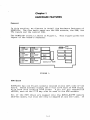
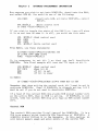
General
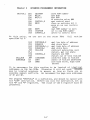
In this section, we discuss in detail the hardware features of
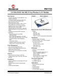
ROMPLUS+. The four basic parts are the ROM sockets, the RAM, the
TTL inputs and the control ROM.
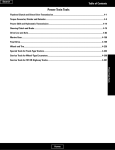
The ROMPLUS+ board is shown in Figure 1.
layout of the board's features.
ROM
SOCKET
#1
ROM
SOCKET
#3
ROM
SOCKET
#5
ROM
SOCKET
#2
RO~l
SOCKET
#4
ROM
SOCKET
#6
I
I
]~
I
I
I
I
RAM
IV
RAM
Control ROM
This figure gives the
I±f±b <?rnputs
TTL
I
I
I
II
II
II
I
FIGURE 1.
ROM Space
ROMPLUS+ has six 24-pin sockets located on the left side of the
board. These sockets accept the 5 vol t 2316 type of ROM chips,
with each chip holding 2048 bytes. A pin for pin compatible
cEPROM, such as the 2716 may also be used in the ROM sockets.
All of the ROM chips are mapped into the $C800-$CFFF memory
address space, but only one chip is mapped at anyone time. If
1-1
Chapter 1
HARDWARE FEATURES
your application program is larger than 2048 bytes, do not worry.
There is a scheme for switching control from one chip to another
chip. This scheme, plus information for creating your own chips,
is given in th~ Advanced Programmers Information chapter.
RAM Space
ROMPLUS+ has 256 bytes of read-write memory (RAM) on-board. This
RAM may be activated or deactivated,under program control.
When
activated, the RAM maps into the $CFOO-$CFFE memory address
space. Notice that only 255 bytes are available.
The last byte
at location $CFFF may not be used. This is because of the Apple
II's peripheral convention which deactivates all peripheral
boards when memory address $CFFF is referenced.
Also, when the
RAM is active, the top 256 bytes of the selected ROM chip are not
a va i I a b Ie. This i s be ca use the RAM map sin tot h e sam e spa c e use d
by the ROM chip. If your ROM chip uses all of its 2048 bytes,
simply deactivate the RAM. See chapter 5 for information on the
control word used to activate or deactivate the RAM.
The RAM will retain its contents whether ROMPLUS+ is active or
not in use. The RAM, of course, loses its contents when power is
switched off.
The RAM provides the ROM chips with their own private storage
area. This will help to minimize memory conflicts. However, the
RAM may be used by any program in the Apple II.
We recommend that the RAM be allocated in the following way:
Address
$CFOO-$CF03
$CF04-$CF5F
$CF60-$CF7F
$CF80-$CF9F
$CFAO-$CFBF
$CFCO-$CFDF
$CFEO-$CFFE
Use
Scratch
Scratch
Scratch
Scratch
Scratch
Scratch
Scratch
area
area
area
area
area
area
area
1-2
for
for
for
for
for
for
for
control ROM
ROM socket 111
ROM socket 112
ROM socket 4;3
ROM socket 114
ROM socket 115
ROM socket 116
Chapter 1
HARDWARE FEATURES
TTL Inputs
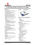
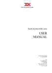
A four pin connector on ROMPLUS+ provides two TTL level inputs
and two ground pins.
A matching four pin plug with wire is
available from Mountain Computer.
Order Part No. MHP-X021.
Price $3.00.
123 4
Left
r!tHJ
Right
Pins 2 and 3 are grounded. Pins 1 and 4 are the TTL inputs. The
inputs are held high by pull-up resistors.
Therefore, an unused
input will be read as a high level, or a "1". The TTL inputs are
read through the control word. Chapter 5 has more information on
the control word. Pin 1 on the connector maps to bit 4 of the
control word.
Pin 4 on the connector maps to bit 5 of the
control word.
Control ROM
The control ROM provides the "intelligence" which makes ROMPLUS+
easy to use. It controls input and output functions and allows
for easy ROM socket selection and entry point selection. Many of
its features are in the next chapter, Using ROMPLUS+.
The control ROM occupies the memory address space $CNOO-$CNFF,
where N is the slot number.
The ROM is supplied with power
whenever it is addressed. This results in a power-saving.
1-3
Chapter 2
USING ROMPLUS+
This chapter covers the basic information you need for typical
operation of ROMPLUS+. This chapter should be read carefully.
We will cover such topics as selecting ROMPLUS+, activating RAM,
ROM socket selection, and entry-point selection.
Activating ROMPLUS+
ROMPLUS+ is a peripheral that is activated in the same manner as
other Apple II peripherals. From BASIC, ROMPLUS+ is turned on by
a "INln" or "PRln" command, where n is the slot number. From
the moni tor, a "nCTRL-K" or "nCTRL-P" command will turn on
ROMPLUS+. If you are running BASIC under DOS, use the regular
DOS procedure of printing a CTRL-D followed by the command.
Whenever the board is activated, the RAM is also activated.
The board is deactivated by using both the "INIO" and "PRIO"
commands. Hi t ting the "RESET" key wilTalso deacti va te ROMPLUS+.
If another peripheral card is accessed via the "INln" or "PRln"
commands, ROMPLUS+ will be deactivated. Of course, any reference
to address $CFFF will deactivate ROMPLUS+ (or any other
peripheral board).
Once ROMPLUS+ has been activated, all input and output operations
are vectored through the control ROM. This is transparent to the
user, i.e., nothing seems different. However, the control ROM is
looking for one of two special command characters.
If the
character passed on input or output is not a special command
character, it is passed to the input or output routine. If the
character is a command, then the next two characters are
interpreted as parameters of the command.
2-1
Chapter 2
USING ROMPLUS+
Commands
The two command characters are CTRL-SHIFT-M and CTRL-SHIFT-N
(ASCII codes $9D and $9E respectively). You may obtain these
characters by pressing the CONTROL, SHIFT, and letter keys
simultaneously. These characters were chosen to minimize typing
accidents.
The syntax of the commands are:
CT'RL-SHIFT-M<ROM socket 11><entrypoint>.
CTRL-SHIFT-N<ROM socket Il><entry point>.
There are no spaces between the command character, the ROM socket
The brackets are not entered. No return
is necessary after the command. Notice the command is three
characters long.
#, and the entry pOint.
ROM socket number is a value from 0 to 6 which specifies which
ROM socket you want to select. Only one ROM socket is active at
one time, but one ROM socket may call another ROM socket.
Selecting chip number 0 will deactivate the current ROM socket
without deactivating ROMPLUS+.
If an invalid ROM socket is
selected, the "bell" will beep.
Entry point is a letter, starting with A, and ending with a
letter depending on the particular ROM chip selected. The number
of entry points on .any ROM is determined by information on that
particular ROM. The first entry point is always "A", the second
entry point is "B", and so on.
If an illegal entry point is
spec i f i ed, the bell wi 11 beep. The documenta t ion accompanying
any commercially available ROM for ROMPLUS+ will detail the valid
entry points of that ROM. If you write your own ROM, you will
place a table of entry points on the ROM. The number of entry
points determines the valid entry point characters.
More
information on writing your own ROM chips is in the next
chapter.
2-2
Chapter 2
USING ROMPLUS+
CTRL-SHIFT-M
This command selects one of the two operating modes of ROMPLUS+.
The CTRL-SHIFT-M command will let the selected ROM gain control
every time a character is inputed or outputed. When this command
is issued, all subsequent input and output is vectored through
two hooks which are located on the selected ROM.
Recall that when ROMPLUS+ is activated, the input and output is
vectored through the control ROM.
This means that when a
character is input, a call is placed to the control ROM which
calls the input driver.
The control-ROM inspects this character
and then passes it along to the program requesting input.
Similarly, on output of a character, a call is placed to the
control ROM, which inspects the character and then calls the
output driver. Whenever ROMPLUS+ is not active, input and output
are not vectored through the control ROM.- Instead, they are
vectored to the normal input and output drivers of the Apple.
When the CTRL-SHIFT-M command is given, the input and output are
now vectored through the input and output hooks on the selected
ROM. Normally, these input and output hooks point to locations
within the selected ROM. More information about the hooks is in
the next chapter.
In general, all of the hooks and vectors are transparent to the
user.
When ROMPLUS+ is deactivated, 1/0 vectors through the
normal Apple II 1/0 drivers. When ROMPLUS+ is active, 1/0 is
vectored through the control ROM. When a CTRL-SHIFT-M command is
gi ven, all subsequent 1/0 is vectored through the selected ROMs'
1/0 hooks. The ROMs' 1/0 hooks are located in the branch table.
More information about the branch table is in the next chapter.
The net effect of the CTRL-SHIFT-M command is that the selected
ROM gains control on every input or output character.
This
continues until ROMPLUS+ is deactivated, or the particular ROM is
deactivated. Examples of the type of program which use this mode
of operation are printer drivers, or Mountain Hardware's Keyboard
Filter.
These programs need to execute with every input or
output operation.
CTRL-SHIFT-N
This command selects one of two operating modes of ROMPLUS+. The
CTRL-SHIFT-N command will pass control to the selected ROM
program.
This program is executed immediately and then control
returns. If this command was printed as part of a BASIC program,
then control returns to BASIC.
If this command was entered
immediately from the keyboard, then control returns to the
keyboard.
2-3
Chapter 2
USING ROMPLUS+
A program executed by the CTRL-SHIFT-N command in one ROM may
execute another ROMPLUS+ program in another ROM by outputting
anothr CTRL-SHIFT-N command. However, a program executed by the
CTRL-SHIFT-N command may not output a CTRL-SHIFT-M command.
In
the former case, the control ROM keeps track of control. In the
later case, the control ROM keeps track of control. In the later
case, we have a situation which is logically meaningless.
It
does not make sense to have a routine type of program calling a
special driver type program.
It does make sense however, to have a driver type program
(activated by CTRL-SHIFT-M) call upon a routine type program
(CTRL-SHIFT-N). For example, a program such as Keyboard Filter
might call upon a routine on another ROM.
It would output a
CTRL-SHIFT-N command. The control ROM keeps track of the ca11ing
ROM and the called ROM. It returns control to the calling ROM
when the called ROM returns.
Selecting RAM
Any time ROMPLUS+ is activated, or any ROM is activated via the
CTRL-SHIFT-M or CTRL-SHIFT-N commands, the on-board RAM is
activated. Whenever this RAM is active, the top 256 bytes of the
selected ROM are not available. If your program uses the top 256
bytes of the ROM, you must deactivate the RAM before the code is
executed. Otherwise, the computer will read the contents of RAM
and interpret that data as instructions. This usually results in
disaster. It is necessary to reactivate RAM before returning
control. The next chapter contains a few rout ines used for controlling the state of the RAM.
Notes
The control ROM on ROMPLUS+ makes use of two locations in memory
normally used by the monitor. These two locations are $3A and
$3B. As a result, whenever ROMPLUS+ is active, the monitor "L"
command for disassembly and the Apple II mini~assembler will not
work properly. To restore these commands, deactivate ROMPLUS+.
The Apple II peripheral scheme states that all ROM's in the
$C800-$CFFF space must be de-selected whenever $CFFF is
referenced.
Therefore, take care that your programs never
reference location $CFFF.
2-4
Chapter 3
ADVANCED PROGRAMMER'S INFORMATION
This chapter contains information for the advanced use of
ROMPLUS+. The sections about the control word and the control
ROM should be read by anyone using ROMPLUS+. The other sections
about the branch table, preparing your ROM, and programs greater
than 2K bytes are intended for the user that will prepare their
own ROM chip for use in ROMPLUS+. However, anyone using ROMPLUS+
will benefit from the information in those sections.
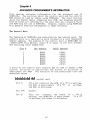
The Control Word
The features of ROMPLUS+ are controlled by the control word. The
control word is a read/write word located at a slot dependent
memory address. The address of the control ~ord is $C080+$NO (or
-16256+l6*N from BASIC), where N is equal to the slot number.
The following table summarizes:
Slot
- -II
Hex Address
1
2
3
4
5
6
7
$C090
$COAO
$COBO
$COCO
$CODO
$COEO
$COFO
BASIC Address
-16240
-16224
-16208
-16192
-16176
-16160
-16144
A write to the control word location may be used to select a ROM
socket, activate or deactivate the board, or activate or
deactivate the RAM.
The function of the particular bits are
described below:
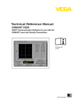
control word
Bit 7:
This bit controls the RAM. If a "0" is written,
the RAM is deactivated. If a "1" is
written,
the RAM is activated.
Bit 6-4:
Unused.
Bit 3:
This bi t
controls the board. If
written, the ROMPLUS+ is deactivated.
is written, the board is activated.
3-1
a
"0" is
If a "1"
Chapter 3
Bit 2-0:
ADVANCED PROGRAMMERS INFORMATION
These bits select the ROM socket to be enabled.
Bit two is the most significant bit of the
value. If the value=O, then none of the ROMs
are enabled. If set from 1 t~6, the corresponding ROM is enabled. The value should never
equal 7.
A read to the control word is used to check the status of the
RAM, find the currently enabled ROM socket number, or to sense
the value of the two TTL inputs. The function of the particular
bits are described below.
control word
Bit 7:
This bit reads the status of RAM. If equal to
"0", then RAM is deactivated.
If equal to "1",
then RAM is active.
Bit 6 :
Unused.
Bit 5 :
TTL input from pin 4.
Bit 4 :
TTL input from pin 1.
Bit 3 :
Unused.
Bit 2-0 :
These bits indicate which Rom socket is currently enabled. The value is determined
the same
way as the bits 2-0 of the written control word.
We next examine several programming examples of control word use.
First, if we wish to activate ROMPLUS+ and select ROM socket
number one, we use these machine language instructions:
LDA #$89
:RAM active, board active, ROM #1
STA $C080,X
:Write control word
In that example, and in the examples to follow, we assume that
the X register contains the slot number (1-7) multiplied by 16.
This is the standard convention for slot independent 1/0 on Apple
II.
To do the same thing in BASIC, we use a statement like this:
POKE -16256+16*SLOT,137
3-2
Chapter 3
ADVANCED PROGRAMMERS INFORMATION
Now suppose you wish to activate ROMPLUS+, deactivate the RAM,
and select ROM #5. You would do one of the following:
LDA #$OD
:Deactivate RAM, activate ROMPLUS+, select
ROM #5.
STA $COSO,X
:Write control word
or POKE -16256+16*SLOT,13
If you wish to toggle the state of the RAM (i.e., turn off when
it is on and turn on when it is off), you would use this code:
LDA
EOR
ORA
STA
$COSO,X :Read control word
#$SO
#$SO
$COSO,X :Write control word
From BASIC, use these statements:
S=(PEEK(-16256+16*SLOT)+12S)MOD 256
IF S MOD 16<S THEN S=S+S
POKE -16256+16*SLOT,S
It is necessary to set bit 3 so that you don't deactivate
ROMPLUS+. This final example will test the TTL input at bit 4.
LDA $COSO,X
BIT #$10
BNE
BEQ
:Read control word
:Mask bit #4
:If bit is set
:If bit is clear
In BASIC:
IF (PEEK(-16256+16*SLOT)MOD 32»15 THEN BIT IS SET
Remember that when writing the control word, bit 3 must be set to
activate ROMPLUS+.
Even if ROMPLUS+ is already active, bit 3
must be set if you do not want to deactivate ROMPLUS+.
If a read of the current ROM chip yields ROM socket number zero
as the active ROM, then no ROM is active.
If ROMPLUS+ is not
active, then the current ROM chip will read as ROM socket number
zero.
Control ROM
The control ROM provides "intelligence" for ROMPLUS+. It is a
256 byte memory which controls the functions of ROMPLUS+.
A
complete source listing is in the Appendix. In this section, we
will detail memory usage and entry points of the control ROM.
3-3
Chapter 3
ADVANCED PROGRAMMERS
INFOR~ATION
The control ROM uses two bytes of memory in the zero page. These
two locations are $3A and $3B. These two locations were chosen
to take advantage of the monitor indirect jump at $FEBC. The use
of the two page zero memory locations ($3A & $3B) causes a memory
conflict with two of the monitor's commands.
As mentioned
erlier, when ROMPLUS+ is activated, the mini-assembler and the
disassembler will not work.
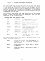
Additionally, the control ROM uses seven bytes in the screen
space.
These locations are slot dependent, and they are
summarized in the following table.
S:t:mbolic Name
B:t:te Location
Usage
CHIP
$478+SLOT#
Contains active ROM socket #
for CTRL~SHIFT-M commands
MODE
$4F8+Slot#
Used to parse commands
WHICH
$578+Slot#
Used to hold the entry point
letter
CUR CHIP
$5F8+Slot#
Contains number of most recently used ROM socket
TCHIP
$678+Slot#
A scratch location
SO
$6F8+Slotil
Contains
#
MSLOT
$7F8
*
the
value
(Slot
16)
Contains the
where N=Slot#)
The control ROM has three entry points.
number, the entry points are:
value
($CN
Assuming that N = Slot
$CNOO
Initial entry point, used when ROMPLUS+ is
activated. It will initialize variables
and IIO hooks.
$CN06
Output entry point.
a character.
$CN08
Input entry point.
character.
3-4
Vector here to
output
Vector here to input
a
Chapter 3
ADVANCED PROGRAMMERS INFORMATION
The Branch Table
Every ROM tha tis to be used on ROMPLUS+ must have a branch table
at the beginning of the ROM. The branch table allows the user to
select an entry point into the ROM by using just a letter to
des i gna te the entry po i n t. A summary of the branch table is as
follows:
Address
$C800
$C802
$C804
$C805
$C807
$C805+(2*(n-1))
Address of output hook routine
Address of input hook routine
Value which indicates length of Branch
table
Address for entry point #1
Address for entry point #2
Address for entry point #n
All of the addresses are 2 bytes long, with the low order byte
first.
All branch tables must have at least one entry point.
With only one entry point, the branch table would end at $C806
and the value of the byte at $C804 would be $07.
The value
contained at $C804 is the total number of bytes in the branch
table.
Therefore, if there are "N" entry point address, the
value of $C804 is (2*N+5).
The input and output hook address ($C800 and $C802) are used by
the CTRL-SHIFT-M command. $C800 contains the address of the
routine to be called every time a character is to be outputed.
This output hook address is usually the address of a routine on
that particular ROM. $C802 contains the address of the routine
on a particular ROM to be called every time a character is to be
inputted. All character 1/0 routines should end with a return
from subroutine instruction. If the ROM that you write does not
use the CTRL-SHIFT-M command, then these 1/0 hooks will not pOint
to a routine on the ROM. Instead, you should use the addresses
of the standard Apple 1/0 drivers.
The output hook, $C800,
should contain the address $FDFO, with the low oder byte first.
Likewise, the input hook, $C802, should contain the address
$ F D1 B. Th e s e I I 0 h 00 k son the ROM mu s t a I way s poi n t to val i d I I 0
routine addresses.
The branch table is the only requirement for ROM's.
The
application program's code may begin immediately after the branch
table.
3-5
Chapter 3
ADVANCED PROGRAMMERS INFORMATION
Writing Your Own ROM
There are a few things you should remember when writing your own
ROMs. First, your program should never reference location $CFFF.
Any reference to that address will disable all memory that maps
into $C800-$CFFF. If you do reference that address, you will
disable ROMPLUS+.
The slot number of ROMPLUS+ may be found by your program by
reading $7F8. It will contain the value $CN where N is the slot
number. Location $6F8+N contains the value $NO.
The control ROM makes sure that RAM is active whenever a ROM
socket is selected. If your program must deactivate the RAM, it
must reactivate RAM before it finishes executing.
Programs On Two ROMs
The 2K bytes of storage on each ROM is large enough for all but
the larger programs. If you have an application program that is
larger than 2K bytes, there is a scheme allowing you to use two
ROMs in conjunction.
ROMPLUS+ will map anyone of the six ROMs into the $C800-$CFFF
address space at one time~ If you simply had the first ROM write
a con t r 0 1 w0 r d wh.i c h s wit c h est heR OMs 0 c k e t n u mbe r tot hen e w
ROM socket number, your program will immediately swi tch to the
other ROM. This usually blows up the program.
One solution to this problem is to write a subroutine dispatching
subroutine, and place this subroutine into identical addresses on
the two ROMs. This way, you enter the subroutine dispatching
subroutine on the first ROM, the switching of ROM occurs, and the
dispatching routine continues on the second ROM, because the
identical addresses contain identical code.
Here is the code which will do the task:
*The A register contains the ROM socket number
*you wish to use. The Y register contains a
*value which determines which routine is run (routine
*number *2). You must preserve the X register.
MSLOT
CONTROL
CHIPNUM
SUBADDR
EQU
EQU
EQU
EQU
$7F8
$C080
$0
$1
3-6
Chapter 3
CHIPCALL
At this point,
specified by Y.
CALLSUB
SUBTABLE
ADVANCED PROGRAMMERS INFORMATION
STA
LDX
LDA
TAX
LDA
ORA
PHA
CHIPNUM
MSLOT
$638,X
AND
ORA
STA
II$F8
CHIPNUM
CONTROL,X
CONTROL,X
11$08
:save ROM number
:get $CN
:get $NO
:x contains value $NO
:get control word
:turn on activate bit 3
:save so we can restore
later
:set ROM number to zero
:or in new ROM number
:write to control word
we are now on the other ROM.
LDA
STA
LDA
STA
JSR
PLA
STA
RTS
JMP
DA
DA
SUBTABLE,X
SUBADDR
SUBTABLE+1,y
SUBADDR+1
CALLSUB
CONTROL,X
(SUBADDR)
SUB1
StJB2
Call routine
:get low byte of address
:and store here
:get high byte of address
:and store here
:indirect subroutine call
:return, get old state
:restore old ROM
:return out of this routine
:indirect jump to routine
:table of routine addresses
:low byte first, high byte
second
It is necessary for this routine to be located
addresses on the two ROMs. Otherwise it will not
may be located anywhere in memory as long as
possible memory conflicts. We recommend the page
of $1 and $2.
at identical
work~-SUBADDR
there are no
zero addresses
The program "CHIPCALLw is a subroutine, and should be called with
the "JSR" instruction. Before you call the subroutine, set up
the "A" and "Y" registers. The value of the X register must be
preserved.
3-7
Chapter 4
REFERENCE
This chapter is a concise description of the hardware and
software of ROMPLUS+.
It is intended to serve as a reference
section only.
The hardware features of ROMPLUS+ are:
1.
Sockets for six 2K ROMs (2316) or EPROMs (2716).
Total ROM capacity is 12K bytes. ROM is selected by
software.
2.
256 bytes of RAM which can be enabled or disabled under
software control.
3.
Two TTL levels inputs which are held high by pull-up
resistors. The inputs are read from the control word.
4.
A 256 byte control ROM which controls the operation
ROMPLUS+.
of
The software features of ROMPLUS+ are summarized below:
1.
2.
3.
ROMPLUS+ is activated by the "INfln" or "PRfln" commands
from BASIC. ROMPLUS+ is deactivated by both "INfln"
and "PRfln" commands, or by RESET,
or SY--referencing
location $CFFF.
There are two modes of operation available.
modes are selected by these commands:
These
a)
CTRL-SHIFT-M:
This mode will run the selected ROM
program every time a character is
inputted or outputted.
b)
CTRL-SHIFT-N:
This mode will run the selected ROM
program immediately,
and
then
return control to the calling program.
The command structure is:
CTRL-SHIFT-M<ROM socket number><entry point>
CTRL-SHIFT-N<ROM socket number><entry point>
The "CTRL-SHIFT-letter" character is typed by holding
down the CONTROL and SHIFT keys while typing either "M"
0r
"N".
<ROM socket number> is a value from 0 to 6, and selects
4-1
Chapter 4
REFERENCE
a ROM socket. ROM socket zero will disable
all the
ROMs without disabling ROMPLUS+. <entry point> is
a
character used to select the entry point into the ROM.
All ROMs must have at least one entry point.
Entry
point A is the first entry point, B is the second entry
point, etc.
There are no spaces between the command character,
the Ram socket number, and the entry point character.
The brackets are not typed.
4.
RAM is enabled and disabled by bit 7 of the control
wor'd. The top 256 bytes of any selected ROM is
not
by
available when RAM is enabled. If RAM is disabled
any ROM, then
it must
be
enabled before the ROM
returns.
4-2
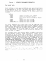
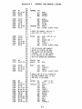
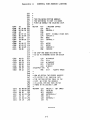
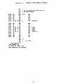
Appendix A
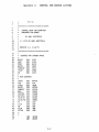
CONTROL ROM SOURCE LISTING
General Information
The following pages contain the Control ROM Source listing. Once
ROMPLUS+ has been activated, all input and output operations are
vectored through the control ROM. This is transparent to the
user. The Control ROM is looking for one of two special command
characters (CTRL-SHIFT-M or CTRL-SHIFT-N.)
If the character
passed on input (or output) is not one of these special commands,
then it is passed on to the input routine. If the character is
one of the special commands, then the next two characters are
interpreted as parameters of the Control ROM command.
NOTE
The Control ROM makes use of two locations in memory
that are normally used by the monitor. These two locations are $3A and $3B. Whenever the ROMPLUS+ card is
active, the monitor "L" command for disassembly and the
Apple II mini-assembler will not work properly.
A-1
Appendix A
PPT ON
1
2
CONTROL ROM SOURCE LISTING
:f;
,f;******;+;**;~;*******;"'*************
4
5
6
7
8
9
10
11
12
13:
:+:
:+:
*
CONTROL PFWt'l FOr::: ~10UNTA I N
HARN~AF:E ROM BOARO
:+:
B'r' AND'T' HERTZFElD
:+;
:+: <: C"
1979 B',.' AND'r' HERTZFElO
*
*
* VERS I ON 1. 6,. 4,/16/79
14
""
**********:+:""**************"''''**'''*
16
:+:
:+:
17
18
19
20
21
22
.-,""7-
~..::.
24
25
mUATEs FOR SCREEN SPACE
'MSlOT
"
E!U
EQU
EQU
~10DE
EQU
WHICH
CURCHIP EG!U
EQU
TCHIP
EQU
50
CHIP
$7F8
$::88
$438
$4B8
$53::::
$5B8
$638
26
:+:
27
:+: t1ISC EQUATES
*
IORTS
mu $FF58
EQU $36
CSI~
EQU $100
STACK
ROKE',.'
EQU $FD1B
CHAROUT EG!U i=mF0
BEll
mu :$FBOD
CONTROL EG!U $C080
ENTRIES EG1U $(:800
CHIPLlt1 EQU '$C:::(14
GOVECTOR E(::!U $FEBC
PC
EG!U BA
CTlA
EG!U $9D
EQU $8D
CR
EQU $9E
CTlS
EQU $3A
SCTlA
*
.-..-,
c;..:.
29
30
31
32
34
35
3:6
::9
40
41
42
43
44
45
46
47
*
ORQ
OBJ
$63130
$630(1
A-2
Appendix A
48
49
50
51
52
-'
.5~
54
55
56
co"",
-_, i
6300:
6303:
6304:
6306:
6307:
6308:
6309:
630A:
630B:
G30C:
630():
630E:
630F:
6310:
6311:
6314:
6315:
6316:
6317:
6318:
6319:
631A:
631B:
631C:
6310:
632(1:
63:21:
~-:-.~
.......
_,~.,,,
6323:
6324:
6325:
6::28:
6328:
2C 58 FF 58
59
38
60
70 04
38
61
90
62
63
18
64
B8
65
66
67
48
68
SA
69
48
70
98
71
7;;-!
48
08
73
74
75
76
77
78
79
80
81
*'
*' WE USE 3 DIFFERENT ENTRY
*' POINTS: "FIRST", FOR THE
*' INITIAL ENTRY AND "0ENTR'r'"
*' AND "IENTRY" FOR THE OUTPUT
*' AND INPUT RE-ENTRIES. THE
*' C AND V BITS ARE USED TO
*' REMEMBER WHICH ENTR'T' OCCUR ED.
*'
*'FIRST BIT 10RTS SET ',/FLAG FOR
OENTR'T'
I ENTRY
*'
*:+:
84
85
,c;~
87
*':+:
*'
*:+:
HD~
mrCK TO SAVE A B'iTE
90
j HIDE A'::.' BRANCH OFFSET
CLC
CLV
PHA
TXA
PHA
TVA
PHA
PHP
NAKING A [)Ut1NY ']SI': WHICH mLL
LEA . . . E OUI': ADDF.:ESS ABOVE THE
STACK. INTERRUPTS MUST BE
DISABLED.
SEI
JSI':
TSX
PLf!
PLf!
PLA
PLA
TA'r'
[)D':
'.0
68
88
A8
89
CA
913
9A
91
68
92
80 F8 07 93
AA
94
eA
95
OA
96
OA
97
OR
98
90 38 06 99
BD B8 03 130
9() ';"'-' 05 101
IORTS DUNN'r' ..lSR
.; RECOVEF.: INPUT CHARACTER
.; AND KEEP IN 'r' REGISTER FOR
T~-::S
PLA
STA
TAX
ASL
ASL
ASL
RSL
STA
LDR
STA
~·c,
1~)2
..
:+:
:+: Nm~ ~,jE MUST FIND OUT WHAT SLOT
:+: i4E "I<:E IN. THIS IS ACHIEVED B'r'
:=;.-
.0
INITIAL ENTRY
MAKE INITIAL ErHI':'T' OUTPUT
ENTF.:'r' AU~A'r'S TAKEN
SEC
BVS
SEC
COMMON ENTF.:'!' POINT
ENTR'T'
78
82
210 58 FF :::3
BA
68
68
CONTROL ROM SOURCE LISTING
GET $CN FRON STACK
MSLOT
; SLOT # IN X
.'
SO, >~
CHIP, X
CURCHIP,X
:+:
A-3
Nm,~
Appendix A
612E:
612F:
6110:
6132:
6315:
6337:
6139:
633B:
633D:
633F:
6341:
6343:
6346:
6348:
6J4A :
634C:
634F:
28
08
50 16
101
104
105
106
107
108
109
:+:
:+: NOW RECOVER STATUS AND GO TO
:+: THE PROPER ROUTINE ACCORDINGL'T'
:+:
110
111
:+:
:+: THE FOLLOWING CODE IS FOR THE
:+: INITIAL ENTRY ONTO THE BOARD.
112
113
114
115
116
AD F8 07 117
85 37
118
85 39
119
A9 06
120
85 36
121
A9 08
122
85 38
123
A9 00
124
9D B8 03 125
F0 35
126
127
128
129
B0 07
PLP
PHP
BVC
j
~'E-ENABLE INTERRUPTS
.; SAVE STATUS
REENTRY
1·IE INITIALIZE OUR VARIABLES
ANO SET THE HOOKS TO POINT TO
:+: THE RE-HHR'r' POINT.
:+:
:+:
:+:
INIT
L[.lA
STA
5TA
LOA
5TA
L['A
STA
LDA
STA
SEQ
MSLOT
CSW+1
CS~J+J
#(OENTR',-'
CSW
#< I ENT":',-'
CSW+2
#$00
CHIP,. X
RESET
AUIA'T'S TAKEN
:+:
:+:
14E CO~lE HERE FOR A RE-ENTRY.
[·JE CHECt~ FOR COMMANDS JUST
ON OUTPUT. AT THIS POINT THE
CARR',-' ST I LL MARKS ~IHERE
WE CA~lE FROM.
1::::;0
1<:'1
132
:+:
:+:
:+:
:+:
133
134
:+:
13:5
REENTR'y'
136
137
13E:
139
:+:
:+: SET WHICH TO INPUT HOOK
:+:
A9 02
9D 88 04 140
D0 56
141
142
143
6351:
6353:
CONTROL ROM SOURCE LISTING
144
145
146
147
A9 00
148
9D B8 04 149
of:
BCS
LDA
STA
BHE
OUTHOOK
#$02
WH I CH.. :x:
'./ECTO":
ALWA',-'S TAKEN
:+:
:+: HERE WE HAN[)LE THE OUTPUT HOOK
:+: WE SET MH I CH AN[) UPDATE THE
:+:
:+:
:+:
CURRENT CHIP AND THEN GO CHECK
FOR CO~1MANDS.
OUTHOOK
150
151
152
:+;
153
154
155
156
157
:+:
:+:
:+:
:+:
:+;
:+;
:+:
LOA
STA
#$0
14HICH,
::.~
THE FOLLOWING ROUTINE CHECKS
FOR THE CHIP INITIALIZATION
COMMAND.
IT IS CALLED ONL'T'
ON OUTPUT TO PREVENT THE SAME
CHARACTER FROM PASSING THROUGH
TWICE, THE MODE VARIABLE KEEPS
TRACK OF OUR CURRENT STATE.
A-4
Appendix A
6356:
6357:
635A:
635C:
635E:
636121:
6362:
6364:
6366:
6369:
15:::
98
159
BC 38 1214 16121
1121 eF
161
D0 29
162
163
C9 90
164
Fe 1214 165
C9 9E
166
DO 41
167
9D 38 1214 168
Fe 3C
169
17121
171
172
i73
636B:
6360:
636F:
6371:
6374:
6377:
49 B0
174
f'Q 1217
175
BO 1219
176
lE 38 04 177
90 B8 05 178
De 2E
179
637D:
617F:
6182:
6385:
COMMAND TYA
lDY
BMI
BNE
CMP
BEQ
CMP
BNE
SAVE MODE STA
BEG!
eA
E9
90
A9
9D
BD
9D
GETNlIM
:+:
1'-'-:'
0',,::.
:+:
:+:
ce
De
9D
BC
1219
99
:+:
186
*:+:
1--'-'
C'I
:+:
7D
B8 04 202
121121
203
38 04 21214
B8 0S 205
18 1215 21216
3A
21217
eB
21218
B8 1213 21219
38 1216 21121
88
211
8121 ce 212
AU·1A'T'S TAKEN
'·lECTOR
:+:
:+:
197
19:::
199
2(1121
21211
#CTlA
SAVEMO[)E
#CTlB
VECTOR
MODEJX
'" PARSE THE NUr1BER . CHECKING TO
';+:"" MA!<E SURE ITS FROr'1 121 TO 6.
180
48
1:::8
20 DD FE: 189
19121
A9 00
191
9D 18 (15 192
90 38 (14 19J:
Fe 2121
194
195
MODE. X
GETNIJM
GETINIT
:+:
181
10::""
'-'':'
196
6387:
6388:
638A:
6380:
638F:
6392:
6395:
6398:
639A:
639C:
639F:
63A2:
63A4:
:+:
J,J
184
1:::5
6379:
637A:
CONTROL ROM SOURCE LISTING
EOR
#$8(1
C~lP
#$~37
BeS
ASl
STA
BNE
NOGOO[) AND ( 7
Mo[)E.. ;,(
TCHIP . X
VECTOR AlWA'r'S TAKEN
MUST 8E )=0
THE FOLLOt·HNG CODE HANDLES
EF:ROR5 B'r' RINGING THE BELL
ANO CANCELLING AN'r' PARTIAL
CCrl'lt1ANDS, ITS IN THIS WEIRD
PLACE BECAUSE OF THE 6502.-'5
f<:ELATIVE ADDRESSING CONSTRAINT.
NOGOOD2 PHA
NOGGGD .lSI':
*
I':ESET
lDA
STA
STA
BEQ
BELL
#$121
CIJRCHIP . :<
MODE.. >~
VECTOR AUIA/T'S TAKEN
:+:
:+:
:+:
HANDLE THE SELECTION PAF:At'lETEI'~
BUT DOWT EF.:F.:OR CHECI< IT TILL
*' THE CHIP IS ACTIVATED
'GETINIT
"
SEn~HICH
ASL
S8C
STA
LOA
STA
lDA
STA
CPY
BNE
STA
LD'r'
ORA
STA
. CARR'{ IS SET
#:f:7()
.'
t~HICHJ
>::
2:v'A-S
#$121
~10DE . X
TCHIP,X
CURCHIP,X
#SCTLA
VECTOR
CHIP, X
se,x
#$88
CONTROL, 'T'
A-5
CONTROL ROM SOURCE LISTING
Appendix A
213
63A7:
63A8:
63AB:
63AE:
63AF:
63B2:
63B5:
63B7:
63BA:
63BB:
63BE:
63C1:
63C4:
63C6:
63C8:
63CA:
63CC:
63CE:
6300:
63D2:
214
215
216
217
218
219
28
220
BC 38 06 221
B9 80 C0 222
48
223
AD
BD
09
99
FF CF 224
38 05 225
88
226
80 C0 227
68
228
8D
8C
BD
D0
02 CF 229
03 CF 230
38 05 231
0E
232
A9
85
A9
B0
A9
85
D0
FD
3B
F0
02
1B
3A
12
234
235
236
237
238
239
240
241
242
243
244
245
246
247
248
249
25(1
251
252
63D4: BC B8 (14 253
63D7: CC 04 C8 254
63DA: B0 9D
255
63:[:{: : B9 01 C8 256
63DF: 85 3E:
6J:El : B9 00 C8 258
63E4: 85 3A
259
*
*
** THE FOLLOWING ROUTINE HANDLES
* THE VECTORING TO CHIP 1/0 HOOKS
* FIRST WE ENABLE THE SELECTED CHIP.
*VECTOR
PLP
LDY
LDA
PHA
LDA
LDA
ORA
STA
PLA
STA
ST'T'
LDA
BNE
j
RECOVER STATUS
S0,X
CONTROL, 'y'
$CFFF [) I SABLE OTHER I':ot'lS
CURCH I P, ><:
#$88
CONTROL Y
$CF02
$CF03
CURCHIP, ><:
VECHOOK
* NO CH I P HAS BEEN ACTI VATED 'T'ET
* SO
GO TO STANDARD KE'T'I N OR KE'T'OUT
LOA
STA
LOA
BCS
LDA
ITSOUTPUT STA
BNE
#)CHAROUT
PC+1
#{CHAROUT
I TSOUTPUT
# (RN:::E'y'
PC
D:; IT
ALWA'T'S TAKEN
*
** NOW ~4E OBTA I N THE PROPER
'" TO VECTO!<: TO B'T' I N[:'E;:'~ I NG
* THE INITIALIZATION TABLE
:+:
:+:
:+:
ADDRESS
I rHO
ON THE
CH IP. ~JE STORE THE ADDI':ESS
IN LOCA5L RAM AND THEN '·lECTOR
THERE B'T' AN I ND I RECT .JU~lP
*VECHOOK LOY
CP'T'
BCS
LDA
STA
LDA
STA
~JHICHJ X i GET INDEX
CHIPLIM
NOGOOD2
ENTR I ES+1 . Y
PC+1
ENTRlES, 'I
PC
xxxxxx
A-6
Appendix A
63E6:
63E7:
63E8:
63E9:
63EA:
63EB:
68
A8
68
AA
260
261
262
263
264
'"
* NOW
* THE
*
CONTROL ROM SOURCE LISTING
l~E RESTORE REGISTERS AND GOTO
HOOK ROUT INE.
EXIT
~65
266
267
68
268
20 BC FE 269
270 *
63EE: 48
271
63EF: 98
272
63F0: 48
273
63F1: AC 03 CF 274
63F4: AD 02 CF 275
63F7: 09 08
276
63F9: 99 80 C0 277
63FC: 68
278
63FD: R8
279
63FE: 6S
280
63FF: 60
281
282 *
283 *
ALL
284 *
285 *
--- END ASSEMBLY --TOTAL ERRORS: 00
256 BYTES OF OBJECT CODE
WERE GENERATED THIS ASSEMBLY.
PLA
TAY
PLA
TAX
PLA
JSR
PHA
TYA
PHA
LDY
LDA
ORA
STA
PLA
TAY
PLA
RTS
GOVECTOR
$CF03
$CF02
#$08
CONTROL,V
DONE~
A-7