1
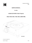
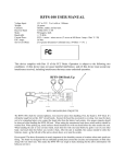
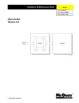
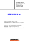
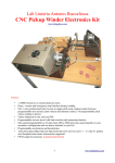
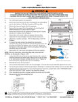
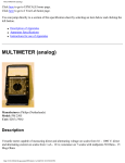
Laboratory 2
Laboratory 2
More Resistor Networks and Potentiometers.
Introduction
page 1 of 5
Parts List
100K potentiometer
single-strand 22 gauge wire
various 5% resistors
9 V battery
battery clip
BLIP board and parts
(without chips)
This is a relatively short laboratory, because while some of you are
doing it, others of you will be using one of the soldering irons in the lab
to put together your BLIP (Breadboard Laboratory Interface Processor).
The BLIP was designed and programmed by former Pitt Bioengineering
undergraduate, David Weiser, and you each will own one. You will
learn how to use it in subsequent laboratories, but for now your job is
just to construct your very own BLIP by soldering the parts onto its printed circuit board (PCB).
Procure your BLIP baggie with the little PCB and all the parts from your TA. (A) Download or view online
the BLIP User Manual from the course schedule for Lab 1. The Parts List for the BLIP is in Section 2.2.1 of
the BLIP User Manual. Make sure all the parts listed are in the baggie, except for the chips, which we will
hand out later. Follow the instructions in the BLIP
User Manual to solder the parts to the board and
have your TA inspect the board. Take care and
enough time to do a good job with soldering your
BLIP, as repairing it later is never as satisfactory. (B)
You will not actually be inserting the chips and
testing the BLIP until a later laboratory.
If you find that all the soldering irons (we only
have five or six) are occupied, proceed to the rest of
the lab, in which you will build some more resistor
networks, learn about the variable resistor
(potentiometer) and make some interesting
measurements and calculations. Come back to
finish your blip when the soldering irons are free
(perhaps even some other time during the week).
1/16/13
© 2013 George Stetten
Laboratory 2
page 2 of 5
The Variable Resistor (Potentiometer)
The potentiometer (or simply “pot”) is an essential component in many electronic circuits, because it
provides the ability to adjust voltages and currents by changing the location of a “wiper” on a special resistor.
The pot you will use contains a semicircular 100K resistor (below left) with a “single turn” wiper that is swept
from one end to the other, by turning the little screw over a range of about 300 degrees, as shown in the
diagram (below center). The schematic for the pot (below right) indicates the value of the underlying fixed
resistor and the direction of motion effected by turning the screw clockwise (CW). Turning the screw
clockwise (CW) moves the wiper towards the 3 pin end of the resistor.
2
1
3
1
2
3
1/16/13
© 2013 George Stetten
Laboratory 2
page 3 of 5
The pot is shown below inserted into the breadboard so that each pin occupies a different column. The
pins, numbered as before, 1, 2 and 3, are shown here resectively (in this case) in breadboard columns 22,
23, and 24. Purple leads are shown coming from the ends of the resistor (pins 1 and 2) and a green lead is
shown coming from the wiper (pin 2). The central screw is seen pointing at about about the “2 o’clock”
position. Turning the screw clockwise (CW) moves the wiper towards the 3 pin end of the resistor.
Using your ohmeter, measure
the total resistance across the
resistor in the pot, between pins
1 and 3. (C) Then, attach your
ohmeter between leads 1 and 2
and turn the pot. Record the
behavior of this resistance as a
function of the direction and the
extent of rotation. Repeat for the
resistance between pins 2 and 3.
(D)
2
1
3
Set the pot at about 2 o’clock
as shown in the picture. Record
the resistance between pins 1
and 2 as well as the resistance
between pins 2 and 3. Does
their sum approximately equal
the total resistance between pins
1 and 3? (E)
1/16/13
© 2013 George Stetten
Laboratory 2
page 4 of 5
Using a Pot as a Voltage Divider, and the Effect of a Load
One of the most common uses of a pot is to deliver some fraction of a given voltage. As shown in the
schematic below, the wiper in effect divides the pot into two resistors whose ratio can be adjusted, providing
any desired voltage between the battery voltage VB (should be a little more than 9 V) and zero volts (ground).
Note that the schematic does not show the connections between the various grounds in the circuit, although
you should provide those connections by using one of the (-) horizontal busses on your breadboard. Build
the circuit, attaching your voltmeter (on the 20 V full scale setting) as shown, and record the behavior of the
output voltage as you turn the screw on the pot, as a function of the direction and extent of rotation. (F)
Adjust the output voltage Vout to exactly 5 volts. Then measure VB and compute the values of the “two
resistors” on either side of the wiper. Without changing the setting of the pot, disconnect the battery and
measure these resistances directly (between pins 1 and 2, and pins 2 and 3, respectively). Compare the
measured resistances to those you computed. Why did you disconnect the battery to make these
measurements? (G)
Without changing the setting of the pot, reconnect the battery and the voltmeter to recreate the circuit
below. Then put a 10K “load” resistor (not shown) across the output (between pin 2 of the pot and ground)
and record the new output voltage Vout. Draw the circuit including the 10 K resistor and derive an equation
that yields the new output voltage, as a function of VB and the two resistances you computed above. (H)
+
-
1/16/13
© 2013 George Stetten
Laboratory 2
page 5 of 5
The Wheatstone Bridge
The Wheatstone Bridge is an accurate way to measure an unknown resistance by comparing the
voltages between two voltage dividers. By using a potentiometer as one of the voltage dividers, it is possible
to “zero out the voltage” so that the ratio of the dividers match each other. The circuit below is an example of
a Wheatstone bridge. Our goal is to compute the “unknown” value of R2 (which in this case we actually
know to be 62 K). Note that “R3” and “R4” represent the resistances in the pot on either side of the wiper for
a particular setting. Derive an equation for R2 in terms of R1, R3, and R4. (I) Why is the battery voltage VB
not part your equation? (J)
Use the voltmeter adjust the pot so that the meter reads exactly 0 V (you can use the most sensitive
voltage setting, 200 mV full scale to do this). Then, without changing the setting of the pot, dismantle the
circuit and measure R1, R3 and R4 directly using the ohmmeter, and compute R2. Then measure R2
directly and compare to your calculated value. (K) What advantage in terms of accurately determining R2
with the Wheatstone bridge can you see, in not having the battery voltage VB as part of the calculation? (L)
1/16/13
© 2013 George Stetten