1
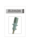
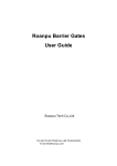
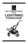
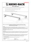
THE MANUAL OF OIL PUMP
Read the following precautions and instructions before you begin assembly or using.
Failure to comply with these instructions could result in personal injury or property
damage. Keep these instructions in a convenient location for future reference.
IMPORTANT NOTE
The guarantee will be void if the pump has been altered in any way
PROFILE
Oil pumps can be used to transfer lubrication oil, waste oil and antifreeze liquids.
This manual is applicable to the following pump only, please confirm your pump is
included.
Specification
Item No.
Compression ratio
Operating pressure(bar/psi)
Maximum pressure(bar/psi)
Air consumption(L/min Gallon/min
Capacity(L/min Gallon/min)
Tube diameter(mm/inch)
Suction tube length(mm/inch)
Air inlet connection
1701051
1701052
5-8/70-115
8/115
240/63.5
12/3.2
42/1.65
42/1.65
42/1.65
270/10.6 or
730/28.7
940/37
Wall installed/
Extension transfer
1/4'' quick plug/1/4'' NPT female
Oil delivery connection
Male 1/2''
Max. viscosity oil delivered
SAE 250
Temperature oil delivered
-10~50 OC
Noise level(dB)
1
1701053
5:1
82
1:1 SERIES OIL PUMP EXPLODED VIEW
2
5:1 SERIES OIL PUMP PART LIST
Appendix
Name
Code
Quantity
Name
Code
Quantity
1
Air motor cover
1
27
Spring shell
2
Air control center
1
28
Spring
2
3
Air motor shell inside
1
29
Spring seat
2
4
Bracket
1
30
Trip shoe guide
2
5
Bracket
1
31
Press piece
1
6
Screw
1
96
Pin
1
7
Shaft
1
97
Pin
1
8
Piston shaft
1
98
Ball
1
9
Piston cover
1
99
Small circlip
2
10
Out cover
1
100
Ball
1
11
Side cover
1
101
Screw
2
12
Suction tube
1
108
Nut
1
13
Slider
1
200
O-ring
1
14
Gasket
1
201
O-ring
2
15
Soft gasket
1
202
O-ring
1
16
Securing washer
1
203
U-ring
1
17
Spring circlip
1
204
O-ring
1
18
Outlet
1
209
Silencer
2
19
Piston
1
212
O-ring
1
20
Valve seat
1
213
U seal
1
21
Filter
1
214
Guiding
1
22
Piston
1
215
O-ring
1
23
Slider
1
216
Quick coupling
1
24
Connecting shell
1
25
Connect shaft
1
26
Air center cover
1
2
Troubleshooting
Problem
Possible Causes
Solutions
The pump continues to operate
after the gun trigger has been
released
1.There is a oil leak at some point of the
circuit
2.Valve sets (part No.22 and 203, 204,
213,214) close incorrectly due to dirt
or wearing.
1.Check and tighten unions.
Repair the leak.
2.Substitute damaged elements
Reduction of the oil delivery.
Or reduced pressure in the oil
delivery.
1.Silencer(209) dirtied
2.Blocked at some point of the oil circuit
3.Ball valve set ( 20,100) closes
incorrectly due to dirt or wearing.
1.Clean or recharge silencer
2.Use clean oil
3.Substitute damaged elements
Air loss through the air exhaust
1.The sliding valve (13) does not close
properly
2.Broken press piece(31)
3.Damaged O-ring(201, 202, 215)
4.Damaged piston (19)
5.Broken spring (28)
1.Disassemble and clean.
Substitute in case of damage
2.Substitute damaged elements
Oil leaks through the air exhaust
Seal set (203,204) damaged
Substitute damaged elements
If the pump has anything wrong, please contact dealer or their technical supporter.
We don't recommend customer repair the pump themselves.
3
STORAGE AND MAINTENANCE
Pumps are delivered in appropriate cardboard boxes. Packaging material should be
properly disposed.
Handling and storage of the new pump do not require any special procedures.
However after the pump has been used, empty the used oil in the suction tube into an
appropriate container. This is done by overturning the pump
The dust in compressed air can slow down and even block the motor cylinder. The
following steps may prevent this from happening:
1) Let in 50 gram of Vaseline oil or other lubricator from the air inlet hole weekly,
operate the pump for several minutes after having lubricator.
2) Turn on the pump for several minutes until moving parts is fully lubricated.
3) You may repeat the above operation if necessary.
4) The above steps should be carried out on a weekly base.
For the pumps that are attached with compressed air treatment equipment please
empty the water retained in the reservoir of the filter-purger frequently.
For the pumps that are attached with a lubricator, please pay close attention to the
lubricator's oil level and refill with SAE 20, SAE 30 or antifreeze oil for extreme
conditions when necessary.
NOTE:
The user should perform only routine maintenance operations (such as filters,
silencers, cleaning...) with the pump in order not to damage it or compromise its safety.
Contact our sales or service centers when the pump needs further maintenance.
GENERAL SAFETY REGULATIONS
When the pump is connected to the compressed air supply:
- The compressed air must be filtered to avoid dust and moisture into pump
- The max compressed air pressure must not exceed 0.8Mpa
- To deliver oil, press the knob on the delivery pistol; delivery stops when the knob is
released but the whole system remains under pressure.
- Position the pistol so that the circuit can't open accidentally. Otherwise oil could
leak onto the ground.
- Never point the pistol at people or objects.
- Press the pistol knob.
- Always cut off the air supply after use so that oil can't leak out in case one of the
pump's components should break
- Use only original spare parts in case the pump has to be repaired or its components
have to be replaced
- Empty all the oil from the pump in case it has to be disposed of.
- When not in use, turnoff compressed air to stop pump.
- Do not use the pump near open flames. Do not smoke during this operation.
- Wear oil-proof gloves
- Do not throw the oil away. Used oil has to be disposed of according to national
Environmental regulations
- The pumps can be used only to deliver lubricants, used oil or antifreeze liquids. Do
not use the pump for any other substance.
4
HOW TO USE
DIRECTLY FITTED PUMPS INTO THE DRUM
1. Insert the suction tube of pump into the drum and secure with ring nut, suitable for
commercial drums with 57 diameter hole and threading 2''BSP
2. Fit a oil delivery tube for oil outlet of the air operated pump using only high quality
tubes (normally 1/2'' or 3/4'', according to DIN-SAE norms), by means of 1/2''BSP
threading fitting.
3. Oil delivery pistol: Connect delivery tube with delivery pistol using suitable pipe
fittings, and point the pistol at right place.
4. Air inlet connection is 1/4'' quick plug(or1/4'' NPT female) in all versions.
Compressed air connection (to be supplied by the customer) should be done using
suitable tubes.
5. A pressure regulator to keep the pump's working pressure at the best possible
level(max 5-8 bar) between the pump and the compressed air line.
6. A cut-off switch can enable the operator to stop the pump at any given
moment by cutting the air supply off between the pump and the compressed air line.
7. Switch on all switch.
WALL INSTALLED
Parts List
Code
5
Name
Quantity
Name
Code
Quantity
1
Oil pump
1
7
Rigid suction tube
1
2
Wall bracket
1
8
Spring circlip
1
3
Pump adapter
1
9
Ball
1
4
Flexible suction hose
1
10
Valve seat
1
5
Suction hose adapter
1
11
Filter
1
6
Bung adapter
1
PROCEED AS FOLLOWS:
1. Secure the bracket to the wall using the dowels at about 1200mm height appropriate
for the tank's dimensions. Make sure that the wall is solid and thick enough for the
dowels. Do not interfere with hydraulic tubes or electric lines.
2. Secure the pump to the bracket 2.
3. Connect the flexible suction tube 4 to the pump using the clamp provided.
4. Connect the rigid suction 7 to the end of the flexible suction tube 4 using the
elastic clamp provided.
5. Put the bung adapter 6 into the drum hole.
6. Put the rigid suction tube 7 into the pump and secure it in place.
EXTENSION TRANSFER
Parts List
Code
Name
Oil pump
1
3-4
Extension 200mm tube
2
Bung adapter
1
3-5
3-1
Top connection
1
3-2
Extension 500mm tube
1
3-3
Name
Quantity
1
Code
Extension sleeve
Quantity
1
Foot connection
1
4
Foot valve
1
5
Filter
1
1
6
PROCEED AS FOLLOWS:
1. Depending on the length of the suction tube the desired extension length.
Can be realized by using the modular extension elements( See the
examples given above)
2. Examples of possible application to pump with drum or rigid suction tube for
Obtaining personalized lengths according to needs.
3.Remove filter and foot valve from the stub pump, screw the extension tube on (W/top
connection), then screw filter and foot valve on the extension tube(foot connection
End!)
CONNECT THE PUMP WITH OTHER ACCESSORIES:
Parst List
Code
7
Name
1
Oil pump
2
Bung adapter
3
Oil pistol
4
Hose with fitting
5
Air hose with quick coupling
6
7(7-1,7-2,7-3)
Drum
Filter, pressure regulator and lubricator
THE MANUAL OF OIL PUMP DISTRIBUTION KITS
PRESSURE RELIEF PROCEDURE
To reduce the risk of serious bodily injury, including fluid injection, splashing in the
eyes or on the skin, or injury from moving parts, always follow this procedure
whenever you shut off the pump, when check or service any part of the
spray/dispensing system, when install, clean or change spray tips/nozzles, and
whenever you stop spraying/dispensing.
1. Shut off the air to the pump.
2. Point the outlet of grease gun to container and trigger the grease gun to relieve
pressure.
IMPORTANT NOTES:
If you suspect that the spray tip/nozzle or hose is completely clogged, or that pressure
has not been fully relieved after following the steps above, VERY SLOWLY loosen the
retaining nut or hose end coupling and relieve pressure gradually, then loosen
completely. Now clear the tip/nozzle or hose.
KITS EXPLODED VIEW
Kits List
Item No.
1700322
1700332
1700333
Drum application
30-50kgs/120lbs
180-220kgs/400lbs
180-220kbs/400lbs
1701053
5:1 Ratio pump
1701052
1701053
Digital control valve
1781801
1781801
1781801
1/2"*13' connection hose
1763413
1763413
1763413
1708001
1708002
1708003
***
***
M820154/M860154
Drum trolley
1/2"*50' Oil hose reel
8