1
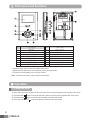
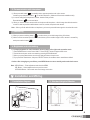
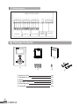
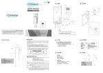
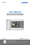
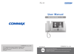
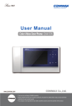
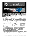
User
User Manual
Manual
COLOR VIDEO DOOR PHONE CDV-35H
513-11, Sangdaewon-dong, Jungwon-gu, Seongnam-si, Gyeonggi-do, Korea
Int’l Business Dept. : Tel.; +82-31-7393-540~550 Fax.; +82-31-745-2133
Web site : www.commax.com
Printed In Korea/ 2010.0 4.101
•
•Thank
Thankyou
youfor
forpurchasing
purchasingCOMMAX
COMMAXproducts.
products.
•
•Please
Pleasecarefully
carefullyread
readthis
thisUser’s
User’sGuide
Guide(in
(inparticular,
particular,precautions
precautionsfor
forsafety)
safety)before
before using
using aa product
product and
and follow
follow
instructions
instructionsto
touse
useaaproduct
productexactly.
exactly.
•
•The
Thecompany
companyisisnot
notresponsible
responsiblefor
forany
anysafety
safetyaccidents
accidentscaused
causedby
byabnormal
abnormaloperation
operationof
of the
the product.
product.
Greetings
1. Thank you for purchasing Commax product.
2. You should read this user’s manual carefully before operating the unit.
Table of Contents
Greetings
----------------------------------------------------------1
Ⅰ. Warnings and caution - - - - - - - - - - - - - - - - - - - - - - - - - - - - - - - - - - - - - - - - - - - - - - - - - - - 2
Ⅱ. Part names and functions - - - - - - - - - - - - - - - - - - - - - - - - - - - - - - - - - - - - - - - - - - - - - - - - 3
Ⅲ. Operation
----------------------------------------------------------3
Ⅳ. Installation and wiring - - - - - - - - - - - - - - - - - - - - - - - - - - - - - - - - - - - - - - - - - - - - - - - - - - - 4
Ⅴ. Package Cotents - - - - - - - - - - - - - - - - - - - - - - - - - - - - - - - - - - - - - - - - - - - - - - - - - - - - - - 5
Ⅵ. Specifications - - - - - - - - - - - - - - - - - - - - - - - - - - - - - - - - - - - - - - - - - - - - - - - - - - - - - - - - - 6
MEMO.
1
Ⅰ.Warnings and caution
2
Ⅱ. Part names and functions
No.
1
2
3
4
5
6
7
8
9
Part name
Monitor
Speaker
Talk Button
Monitoring button
No function
Microphone
Door open button
Interphone button
Power indicator
No.
Part name
10
Menu button
11
SEL button
12
UP button
13
DOWN button
14 Adjustment dial for calling sound
15 Adjustment dial for talk volume
16
Power button
17
No function
18
Terminal
- Adjustment dial for calling sound: Use to adjust calling sound
- Adjustment dial for talk volume: Use to adjust talk volume from counter side.
- DIP switch for camera setting: Use to set up the camera.
Note : It shall be set as camera using mode from manufacturer.
Ⅲ. Operation
1. Calling from visitor
1). When visitor presses the call button on the camera, the chime sounds and appears visitor’ s image on the screen.
2). Press talk button (
) and communicate with visitor. (Maximum 60 seconds is available to talk on the phone)
3). Press talk button(
) again to close and return standby mode after finish the talk.
4). Press door open button (
3
) while on the phone to release the door with melody.
2. Communication with interphone
1). When press talk button (
) on standby status, appears speaker mark on the screen.
And then, press interphone button ( ) to call the interphone. (Maximum 60 seconds available to talk)
2). In case of calling from interphone to monitor, electric melody sounds.
Press talk button (
) to communication.
3). When you have a call from camera while on the phone with interphone, visitor’s image should be showed to
monitor. It shall be possible to talk between each unit, monitor, interphone and camera.
Note : When you finish talk with visitor or interphone, you have to press talk button again to close the talk mode.
3. Monitoring
1). When you press monitoring button (
), monitor shows you outside image during 30 minutes.
2). Monitor can be connected up to 2 cameras and shows you the outside image in order, camera1- camera2 by
each press monitor button(
).
4. Brightness and color setting
1). To Adjust brightness or color resolution, use the button on the right under operation mode.
① Press MENU button to enter“Control Menu”. Press SELECT button to appear basic menu.
② Control the each menu as the user wants by pressing UP/DOWN button.
③ When you press Select button, save the new data and return to basic menu.
④ If you press the Reset button, and press “SELECT”button, all conditions return manufacturer default.
Caution: After changing any conditions, press MENU button to return standby mode under basic menu.
Note : MENU Button – Enter adjustment and close the MENU
SEL Button – Select subject and move previous menu.
UP/DOWN Button – Move each menu and change each value.
Ⅳ. Installation and Wiring
1. Installation diagram
2. Standard Height of Monitor
SCREW M3 X 6mm
SCREW T4 X 18mm
4
3. Wiring diagram
MONITOR (CDV-35H)
1 2 3 4
1 2 3 4
1 2 3 4
1 2 3 4
1 2 3 4
1 2 3 4
CAMERA 1
CAMERA 2
INTERPHONE
1 2 3 4
CAMERA 2 PROGRAM
SELECT
Ⅴ. Package Contents
③
②
①
④
① Monitor (CDV-35H)
② Wall Bracket for mount
③ Manual
④ Wall Bracket mouting Screw
⑤ Monitor fixing Screw
⑥ Connetor(4P)
5
⑤
1EA
1EA
1EA
4EA
1EA
2EA
⑥
Ⅵ. Specifications
CDV-35H
Rating Voltage
AC100-240~, 50/60Hz
Power consumption Max: 15W, Standby:4W
Wiring
Door Camera: 4Wires(Polarity), Interphone: 4Wires(Polarity)
Transmission Way Voice switch circuit(Hands free)
Screen Size
3.5" Color TFT-LCD
Call Sound
From a door camera: electronic chime, From an Interphone : "Beep"
Distance
Camera : 50m(Φ0.65) / Interphone : 20m(Φ0.65)
Form Size
133(W) x 209(H) x 31(D) ㎜
Operating temperature 0 ~+40℃ (32℉ ~ 104℉)
6