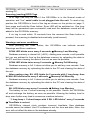
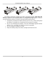
1
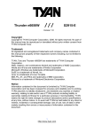
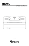
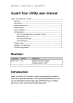
GS1000A/1000AU Patrol Tour Terminal Important Notice! New Features of GS1000AU This Manual refers to GS1000A and new member of the Patrol Tour Terminal family- GS1000AU, an improved version of GS1000A terminal. Notable improvements/additions include: • Attached an USB to RS232 cable (WAS-T0239) to implement communication via USB port. • USB Driver includes in attached CD. • Internal device firmware can be upgraded via USB port. Attention! New Firmware Management mode (FMM) The GS1000Ax (GS1000A or GS1000AU) have two different modes of operation. Normal mode provides regular device functionality and is largely compatible with the original GS1000 operation (see Section 1 for details). New Firmware Management mode (FMM) is provided for internal firmware checkup and upgrades (Section 4). The Normal mode is entered by switching the GS1000Ax (GS1000A or GS1000AU) on while not pressing the Scan button. Switching the GS1000Ax (GS1000A or GS1000AU) on while holding the Scan Button down forces the unit into the FMM. The mode of operation cannot be exited other than by switching the GS1000Ax (GS1000A or GS1000AU) off and powering it on again. Note: The following descriptions about GS1000Ax represent GS1000A and GS1000AU if not mentioned specially. Contents Refer to FAQ 1. Using the GS1000A/1000AU 2. Communications protocol 3 7 3. Using demo software (GuardScan Monitor) 14 4. Firmware Management mode (FMM) 18 5. Test mode 21 6. Specifications 22 Revision: 1.0-a (25/11/2009) 1. Using the GS1000A/1000AU Switching the GS1000Ax on and off To switch the GS1000Ax on for normal operation, slide the Power switch located on the side of the unit while not pressing the Scan button. Switching the GS1000Ax on while keeping the Scan button pressed forces the device into a special Firmware Management mode (FMM, see Section 4 for details). When powered up, the GS1000Ax switches both Scan and B/L LEDs on and performs a firmware check. Upon successful test completion, the unit enters a Normal mode of operation 1 . What happens next depends on whether USB Serial cable WAS-T0239 (or RS232 Serial cable WAS-T0137) is plugged into the GS1000AU (or GS1000A) or not. Note: GS1000AU needs USB Driver which is included in attached CD, please install the deriver first. If the cable is not plugged, then the GS1000Ax will beep and blink Scan LED twice, then go into standby. Device consumes minimal power in this state and will typically last 3-5 weeks on a single battery charge. If the cable is plugged, then the GS1000Ax will beep and its Scan LED will start blinking steadily- the unit is ready for communications with PC. Note that 1 In an unlikely event of test failure, the unit will quickly blink both LEDs for 2 seconds and seize operation. In this case you may need to use the Firmware Management mode to check firmware validity and/or download new firmware. See Section 4 for details. 3 GS1000A/1000AU User’s Manual GS1000Ax will only detect “live” cable, i.e. the one that is connected to the working PC. Scanning (reading) RFID Tags RFID tags can only be read if the GS1000Ax is in the Normal mode of operation and “live” serial cable is not plugged into the unit. To read a tag, position the GS1000Ax in front of the tag as shown on the picture on page 3, then press and hold the Scan button- Scan LED will be switched on. One long beep will be generated upon successful read and the database record will be added to the GS1000Ax memory. If no tag is read within 10 seconds from the moment the Scan button is pressed, the scanning is disabled automatically (read timeout). Warnings and error conditions After pressing the Scan button, the GS1000Ax can indicate several Warnings and Error conditions: SCAN LED blinks once every 2 seconds Memory Low Warning Database memory is almost full (>90%). Adding new records is still possible but you are advised to free up the database memory by uploading the data to the PC and then clearing the data of the unit as soon as possible. SCAN LED blinks twice every 2 seconds Memory Full Warning Database memory is full. It does not allow you to add any new records. Free the database memory by uploading the data to the PC and clearing the data of the unit. After reading a tag, B/L LED lights for 2 seconds with 1 long beep, then SCAN LED blinks twice every 2 seconds Memory Full Warning Database memory is full. It does not allow you to add any new records. Free the database memory by uploading the data to the PC and clearing the data of the unit. B/L LED blinks once every 2 seconds Battery Low Warning The battery is low. Further scanning is not possible. Switch the GS1000Ax off and recharge the battery as soon as possible. Allowing the battery level to drop even further may lead to erroneous machine behavior. “1 long beep + 2 short beeps with 2 B/L LED blinks” every 2 seconds Time/Date is not set GS1000Ax’s internal clock contains incorrect time/date. New database records cannot be added. Use PC software to set the time and date. Note: this error will not affect the data in the database already. 4 GS1000A/1000AU User’s Manual “1 long beep + 3 short beeps with 3 B/L LED blinks” every 2 seconds Database error Internal database error has occurred. New records cannot be added. First, try to switch the GS1000Ax off and back on again- the unit will attempt an autorecovery. If this doesn’t work, use Recover Data function of PC software to recover the database or simply use Clear Data function of PC software to erase the database. If this still doesn’t work, use Invoke Test function of PC software to reset the unit. Note: You can input password “GIGA” when starting software GuardScan Monitor to enable Recover Data and Invoke Test functions. PC Communications To establish communications with PC, switch the GS1000Ax off, plug the cable WAS-T0239 into the GS1000AU’s Serial port (or plug the cable WAST0137 into the GS1000A’s Serial port) and switch the GS1000Ax back on again. Make sure that the cable is “live” i.e. that it is connected to the PC’s USB Serial port for GS1000AU (or PC’s RS232 Serial port for GS1000A) and that PC is on, otherwise GS1000Ax will not be able to detect the cable. Upon cable detection, the GS1000Ax will generate a beep and start blinking its Scan LED. Note: When using GS1000AU, the USB Driver should be installed first. Always turn the GS1000Ax off before plugging or unplugging the connection cable! Failure to do so may disrupt the GS1000Ax database data and possibly result in a permanent damage to the device. Communications mode timeouts automatically in case there is no communications activity for more than 3 minutes. In this case, the GS1000Ax will beep and blink its B/L LED once, then go into standby. PC software can also put the GS1000Ax into standby at any time. Device can only be reawakened by pressing the Scan button. Handling battery To install the battery, insert its “sharper” end into the recess on the GS1000Ax body (1), then push down and snap into position (2). To remove the battery, push the spring holder and pull the battery away from the unit (3). 5 GS1000A/1000AU User’s Manual The battery should be charged only with a specified charger. Note that the battery reaches its full capacity after 3-5 charge/discharge cycles. Observe recommendations below to achieve the best battery performance: • Completely recharge the battery before the first use or after having kept the battery in storage for a long period of time (over 3 months) • Do not over-discharge the battery. Once the GS1000Ax signals that the battery is low, recharge the battery as soon as possible • Do not charge the battery too often • Keep the battery away from direct sunlight and heat sources 6 2. Communications protocol GS1000Ax communications protocol has been extended to accommodate several new commands. At the same time, backward compatibility is maintained with earlier device version (GS1000). Communications between the GS1000Ax and PC take place in the form of commands sent by PC side and replies from GS1000Ax. Commands and replies are packets of data using ASCII control characters to mark beginning and end of packets, acknowledge the data, request data retransmission and so on. Control characters used by the GS1000Ax communications protocol are summarized below: STX 02H ^B Marks the beginning of data packet ETX 03H ^C Marks the end of data packet EOT 04H ^D Indicates the end of data exchange ENQ 05H ^E Marks the beginning of command packet ACK 06H ^F Acknowledges reception of data NAK 15H ^U Requests data retransmission ETB 17H ^W Signals that command or data was not accepted There are two different packet types: command packets and data packets. Command packets start with ENQ character and contain a machine number of the GS1000Ax addressed and command code. ENQ machine number command code 1 character 2 characters 1 character Machine number is supplied as a two-character Hex string and can be in the 00H...FFH range (for example, machine number of 4AH is represented by ‘4A’ ASCII string). 00H is a so-called universal machine number, it will work with any GS1000Ax, regardless of its machine number setting. When using machine number other than 00, make sure that it matches current machine number of the GS1000Ax (set by “P” command). Using universal machine number of 00 will work well in all situations. Command code consists of a single character. See below for complete description of all available commands. 7 GS1000A/1000AU User’s Manual Data packets start with the STX character and end with ETX character. ETX character is followed by the BCC byte. STX 1 ch. Data characters ETX BCC 1 ch. 1 ch. BCC byte is a result of consecutive XOR operations on all data packet bytes excluding STX, ETX and BCC byte itself. It is important to realize that BCC byte can contain any value from 00H to FFH and this also includes control character codes! When designing PC software, be sure to distinguish between BCC byte and control characters. In many cases, reception of data must be acknowledged by the receiving side. This is done by sending the ACK character. In case the receiving side does not accept the data (for whatever reason), the NAK character may be sent to request retransmission. Transmitting side shall make no more than 2 retransmissions (i.e. send the same data no more than 3 times). All retransmit requests in excess of 2 times should be ignored. Note: following the functionality of the original GS1000, the GS1000Ax treats all characters other than ACK as NAK. This means, that when requesting retransmission, the PC can send any character other than ACK to the GS1000Ax, and the GS1000Ax will interpret this as NAK. At the same time, you are advised to use the NAK character for retransmission requests. Summarized below are all supported commands: Modified ‘S’ 53H New ‘T’ 54H Set date/time Get date/time ‘I’ 49H Download database data Modified ‘D’ 44H Initialize (clear) database New ‘M’ 4DH Prepare to recover database data ‘A’ 41H Get total number of records in the database Modified ‘P’ 50H Set Machine number New ‘Q’ 51H Get Machine number New ‘V’ 56H Get firmware version New ‘Z’ 5AH Invoke Test mode ‘O’ 4FH Power down (go into Sleep) 8 GS1000A/1000AU User’s Manual Set Date/Time (‘S’, 53H) PC to GS1000Ax ENQ-M#-‘S’ GS1000Ax to PC ACK* PC to GS1000Ax STX-date/time-ETX-BCC GS1000Ax to PC ACK/(NAK)** PC to GS1000Ax EOT Date/time field has the following format: YYYYMMDDhhmmss, where: YYYY- year, MM- month, DD- date, hh- hour, mm- minutes, ss- seconds. *This command is slightly modified from its original version. Original GS1000 rejected the command in case the database had some data. New GS1000Ax will accept this command regardless of whether there is any data in the database or not. **To maintain compatibility with the original GS1000, the GS1000Ax will accept any date/time data, even if it is invalid (for example, even with the month set to 13). The only situation when the GS1000Ax will return NAK at this point is when BCC check fails. Invalid date/time will not be written into the GS1000Ax’s clock, however. Use new “T” command to verify if new date and time were actually set. Get date/time (‘T’, 54H) PC to GS1000Ax ENQ-M#-‘T’ GS1000Ax to PC STX- date/time field*- ETX-BCC PC to GS1000Ax ACK/(NAK) GS1000Ax to PC EOT Date/time field has the following format: YYYYMMDDhhmmss, where: YYYY- year, MM- month, DD- date, hh- hour, mm- minutes, ss- seconds. *To maintain compatibility with the original GS1000, the GS1000Ax will not explicitly report any clock-related error conditions. Instead, if the date and/or time within GS1000Ax’s clock are not valid (for whatever reason), default date and/or time value will be returned. Default date is 1999/01/01, default time is 00:00:00. 9 GS1000A/1000AU User’s Manual Download database data (‘I’, 49H) PC to GS1000Ax ENQ-M#-‘I’ GS1000Ax to PC STX- first record data- ETX-BCC PC to GS1000Ax ACK/(NAK) GS1000Ax to PC STX- next record data- ETX-BCC PC to GS1000Ax ACK/(NAK) More records… …and acknowledgements GS1000Ax to PC STX- last record data- ETX-BCC PC to GS1000Ax ACK/(NAK) GS1000Ax to PC EOT Record data format: MM,II…I,YYYY/MM/DD,hh:mm:ss, where MM- machine number, II…I- RFID tag’s ID-code, YYYY- year, MM- month, DD-date, hh- hour, mm- minutes, ss- seconds. Machine number reflects current machine number, not the number the unit had at the moment of particular record creation. In other words, machine number is not a part of the record, it is merely added to the record prior to sending it to the PC. With current RFID technology used, all ID-codes have a fixed length of 10 digits. Nevertheless, it is a good idea to not base PC software algorithms on this fact. Future versions of GS1000 and other related products may rely on different identification technologies producing different (and even variable) ID-code lengths. Same considerations also apply to what kind of characters to expect within ID-code field. Currently, the GS1000Ax only outputs characters in the ‘0’…’9’ and ‘A’…’F’ range. However, future product versions may output characters in the 20H…7FH range, but never outside of it. GS1000Ax has a new “M” command that makes the database look like 100% of its capacity is used. This is to be able to download entire database memory contents. When downloading the data after the “M” command, PC can receive the data from GS1000Ax database memory locations that have never been actually written to and, therefore, contain “garbage” data. The GS1000Ax performs some checks on the validity of its own database data. Clearly illegal data is substituted for a fixed valid one in the following cases: 10 GS1000A/1000AU User’s Manual • • • If ID-code of the record has the length other than 10, then GS1000Ax will substitute this with an ID-code consisting of ten ‘0’ characters If ID-code of the record has the length of 10, but some characters within ID-code fall outside of 20H…7FH range, then those characters are substituted for ‘_’ character. If date and/or time stamp of a record is invalid, then it is substituted for default date (01/01/1999) and/or time (00:00:00) Initialize (clear) database (‘D’, 44H) PC to GS1000Ax ENQ-M#-‘D’ GS1000Ax to PC ACK* PC to GS1000Ax EOT This command reinitializes the database. All contents are logically deleted, which means that actual record data is not erased, just some database-related housekeeping is initialized. The database data can still be recovered (if not already written over) using new “M” command. * Original GS1000 did not allow to perform this command on the non-empty database. New GS1000Ax will accept this command at any time, even if the database contains some data. Prepare to recover database data (‘M’, 4DH) PC to GS1000Ax ENQ-M#-‘M’ GS1000Ax to PC ACK PC to GS1000Ax EOT This command alters database in such a way that it appears to be 100% full. Subsequent “I” command will download the contents of entire database memory. This command, therefore, can be used for data recovery purposes. For example, if “D” command is executed accidentally while GS1000Ax had some “useful” data inside, then “M” command can be used to download entire database memory contents. Naturally, this recovered data may not be consistent. Some records may contain “garbage” data (more on this in “I” command description), newer records may overlap older ones, etc. 11 GS1000A/1000AU User’s Manual Get total number of records in the database (‘A’, 41H) PC to GS1000Ax ENQ-M#-‘A’ GS1000Ax to PC STX-number of records-ETX-BCC PC to GS1000Ax ACK/(NAK) GS1000Ax to PC EOT Number of records in the database is returned as a 6-digit decimal string. Leading zeroes are appended to keep the string size constant. Set machine number (‘P’, 50H) PC to GS1000Ax ENQ-M#-‘P’ GS1000Ax to PC ACK PC to GS1000Ax STX-new machine number-ETX-BCC GS1000Ax to PC ACK* PC to GS1000Ax EOT *New machine number is a 2-byte Hex string. Therefore, machine number can have a value in the 00H…FFH range. Unlike previous GS1000 version, this also includes 0 (original GS1000 rejected 0). GS1000Ax also allows the machine number to be changed at any time (old GS1000 would only permit this in case there is no data in the database). Get machine number (‘Q’, 51H) PC to GS1000Ax ENQ-M#-‘Q’ GS1000Ax to PC STX-current machine number-ETX-BCC PC to GS1000Ax ACK/(NAK) GS1000Ax to PC EOT Current machine number is a 2-byte Hex string. Therefore, machine number returned can be in the 00H…FFH range. 12 GS1000A/1000AU User’s Manual Get firmware version (‘V’, 56H) PC to GS1000Ax ENQ-M#-‘V’ GS1000Ax to PC STX-version string-ETX-BCC PC to GS1000Ax ACK/(NAK) GS1000Ax to PC EOT Version string can have a variable length but will never exceed 61 character. Although it is technically possible to have a version string with any kind of ASCII data in it, we commit to the following format: Vx.xx pp…p nn…n, where Vx.xx- version number (i.e. “V1.30”), pp…pproduct model number (i.e. “G-GS1000A”), nn…n- note (i.e. “rev. 01/01/2000”). Version number, product model number and note fields are separated by space characters. Version number and product model number are guaranteed to contain no space characters. Note field can contain any characters including spaces. Invoke Test mode (‘Z’, 5AH) PC to GS1000Ax ENQ-M#-‘Z’ GS1000Ax to PC !!! No reply from GS1000Ax !!! This command is used to force the GS1000Ax into a special Test mode. No reply is issued by the GS1000Ax upon receiving this command. Details of GS1000Ax operation in the Test mode are provided in Section 5. Note that Test mode destroys database memory contents in such a way that the data cannot be recovered even with the “M” command. Power down (‘O’, 4FH) PC to GS1000Ax ENQ-M#-‘O’ GS1000Ax to PC ACK This command puts the GS1000Ax into the low-power sleep mode. Following this command all communications are suspended. The User must press the Scan button to reawaken the device. 13 3. Using Demo software (GuardScan Monitor) The GS1000Ax is supplied with a simple demo program called GuardScan Monitor. The program allows you to setup the machine as well as download the database data from the GS1000Ax into the PC. In addition, the GuardScan Monitor features a Terminal view that protocols all communications between the PC and GS1000Ax. Thus, this software can serve as a great starting point for designing your own GS1000Ax PC software. System requirements The GS1000Ax runs under Windows-98/2000/XP. An Internet Explorer 4.0 or later must be present on the system in order for the GS1000Ax to run correctly. Installation Install the GuardScan Monitor onto your PC by running an installation file. The installation is straightforward and has no differences from a standard installation process for other Windows programs. Installation program will create new GuardScan Monitor icon in the Start/Programs menu. Connecting the GS1000Ax to the PC • • Switch the GS1000Ax off Plug the USB Serial cable WAS-T0239 into GS1000AU, make sure the cable is also attached securely to the PC’s USB serial port; or plug RS232 Serial cable WAS-T0137 into GS1000A and make sure the cable is also attached securely to the PC’s RS232 serial port. Always switch the GS1000Ax off before plugging the cable into it. Failure to do so may result in GS1000Ax internal database data disruption and permanent damage to the device • Switch the GS1000Ax on while not pressing the Scan button. The unit will turn both Scan and L/B LEDs on first (self-check, see Section 1), then beep once and start blinking its Scan LED. This means that the GS1000Ax has detected the cable. Communications between the PC and GS1000Ax is possible from this moment on. Communications between the PC and GS1000Ax is only possible while Scan LED is blinking. If the Scan LED is not blinking, then this means that the GS1000Ax is not in the communications mode. The GS1000Ax can 14 GS1000A/1000AU User’s Manual • only detect “live” cable, i.e. the one that is connected to the powered PC. If, when you switch the GS1000Ax on with the cable plugged in, the unit does not enter communications mode (start blinking its Scan LED constantly) then this means that the cable is not properly attached to the PC, that PC is not powered or that PC’s USB/RS232 serial port is malfunctioning If no communications between the PC and GS1000Ax occurs for about 3 minutes, the GS1000Ax powers itself down automatically- the unit beeps and blinks B/L LED once, then goes into standby. Press the Scan button once to re-awaken the unit. Running the GuardScan Monitor • • • • Make sure that the GS1000Ax is in the communications mode (Scan LED is blinking constantly) Launch GuardScan Monitor When GuardScan Monitor window opens, click on the LOGIN button- the Input login password dialog will appear GuardScan Monitor has two modes of operation- normal and extended. Extended mode and it allows you to issue “special” commands- Recover Data and Invoke Test mode. All other • • • commands are equally accessible in the normal mode as well Input “regular” password (default after installation is “0000” (four “zeroes”) to log on for regular mode or “GIGA” (case-sensitive!) for extended mode. Click OK when done If the password you have entered is correct, then all buttons in the GuardScan Monitor window will become active. Plus, additional Special functions window will appear in the extended mode Select an appropriate COM port from COM Ports frame. The GuardScan Monitor window features a number of command buttons, a Data table that displays GS1000Ax data after downloading and a Terminal view which protocols all communications between the PC and GS1000Ax. GuardScan Monitor allows you to change the default password of “0000”. Press Set password button to set a new password. Note, that login password for extended mode (“GIGA”) is fixed and cannot be changed. Click Upload button to download the GS1000Ax data. This action first invokes “A” command to check the number of records in the GS1000Ax internal 15 GS1000A/1000AU User’s Manual memory, then “I” command to perform actual download. The data, if any, will be downloaded and displayed in the Data table. Rec# field is the record number, Mach# is a machine number of a particular GS1000Ax, ID-code is the ID-code of RFID tag scanned. Finally, Date and Time fields display the date and time of record creation. Click Save to file button to save the uploaded data into a file. The data is saved in a “raw” text file format and can be viewed using simple text editor like Notepad. Each record occupies one line of text and has the following format: MM,Ii…I,YYYY/MM/DD,hh:mm:ss, where MM is machine number, II…I- IDcode of the RFID tag, YYYY- year, MM- month, DD- date, hh- hour, mmminutes, ss- seconds. Click Erase button to delete the data from the GS1000Ax internal memory (invokes “D” command). Make sure that you don’t need the data any more before deleting it. Machine number of the GS1000Ax can be set at any time by clicking on the Set Machine # button (invokes “P” command). Machine number is a 2-digit hexadecimal number which means that it can contain digits from ‘0’ to ‘9’ and characters from ‘A’ to ‘F’. “00”, “23”, “5A”, “B9”, “EC” and “FF” are all examples of correct Machine numbers. You can read machine number back by clicking on the Get Machine # button (invokes “Q” command). Machine number will appear in the reply from GS1000Ax, in the Terminal view: PC:<ENQ>00Q GS:<STX>15<ETX>02 Q-command issued by PC Reply from GS1000Ax contains Machine number (15) Clicking Set time/date button sets GS1000Ax internal clock from the PC clock (“S” command is invoked). GS1000Ax current date and time can be checked by pressing Get time/date button (“T” command). The data will appear in the reply from GS1000Ax, in the Terminal view: PC:<ENQ>00T GS:<STX>20000407114120<ETX>06 S-command issued by PC Reply from GS1000Ax contains date and time (2000/04/07 11:41:20) Clicking Version button produces GS1000Ax internal firmware version 16 GS1000A/1000AU User’s Manual string (“V” command is used). The data appears in the reply from GS1000Ax, in the Terminal view: S-command issued by PC Reply from GS1000Ax contains version string (“V1.30 G-GS1000A”) PC:<ENQ>00V GS:<STX>V1.30 G-GS1000A (standard)<ETX>6E Special functions window has Recover data, Invoke test mode and Power down buttons. Recover data command allows you to download entire database data, regardless of the actual amount of data contained in the database. This is done by first invoking “M” command to make the GS1000Ax database “pretend” that its database is 100% filled with data. Then, regular “I” command is executed to download the data. Finally, “D” command initializes the database. Invoke test mode command forces the GS1000Ax into a special test mode. Test mode is described in details in Section 5. Note that Test mode destroys database data in such a way that it cannot be recovered even using Recover data command. Power down command suspends all communications between the GS1000Ax and the PC and puts GS1000Ax into standby. Press Scan button to reawaken the device and resume communications. 17 4. Firmware Management mode The GS1000Ax features new Firmware Management mode (FMM). FMM allows you to quickly upgrade your GS1000Ax’s internal firmware and also check validity of currently loaded firmware. Contact your dealer for most recent firmware upgrade files. FMM is entered by switching the GS1000Ax on while holding the Scan button pressed. FMM itself has 2 sub-modes of operation: FMM/download mode and FMM/check mode. If the GS1000Ax is switched on with the Scan button pressed and communication Serial cable plugged (USB or RS232), then FMM/download mode is entered (communication Serial cable must be “live”, i.e. it must be connected to the powered PC). If the GS1000Ax is switched on with the Scan button pressed but without Serial cable, then FMM/check mode is entered. Downloading new firmware: To upgrade the firmware, you will need a new firmware file and a terminal software for PC capable of transferring files using Xmodem protocol (Checksum version). All GS1000Ax firmware files have a fixed size of exactly 64K (65536 bytes) and a “.gsf” name extension (although latter is not technically necessary). The list of popular and widely available terminal programs includes HyperTerminal for Windows, QModem, and Term95. Procedure below assumes the use of HyperTerminal which is included into standard Windows98/2000/XP package. To upgrade the GS1000Ax’s internal firmware: • Switch the GS1000Ax off • Plug the USB Serial cable WAS-T0239 into the GS1000AU. Make sure that the other side of the cable is connected to the PC USB port. Or plug the RS232 Serial cable WAS-T0137 into the GS1000A and make sure that the other side of the cable is connected to the PC RS232 port • o Launch HyperTerminal and configure it as follows: When Connection Description dialog opens, type any string (1 character minimum) and press OK 18 GS1000A/1000AU User’s Manual o o o • • • • • • • When Connect to dialog opens, select an appropriate COM port from the Connect Using drop-down box (for example, “Direct to COM3”) When COMx Properties dialog appears, set communications parameters as follows: Bits per second: 19200, Data bits: 8, Parity: None, Stop bits: 1, Flow control: None The HyperTerminal’s main window will appear Choose TransferSend file from the Main menu- the Send file dialog will appear In the Send file dialog, select the *.gsf file you want to download and choose Xmodem protocol from the Protocol drop-down box The Xmodem file send for dialog will be displayed Press and hold the Scan button, then switch the GS1000Ax on. The unit should first turn both Scan and B/L LEDs on and beep, then start downloading data. If, instead of blinking both LEDs and beeping, the GS1000Ax starts blinking its B/L LED and beeping infrequently, then this means that battery level is too low When receiving file, the GS1000Ax will blink its Scan LED (Scan LED is on while GS1000Ax is receiving or expecting to receive a block of data from the PC; Scan LED is off while GS1000Ax is programming the data received into its internal memory) Once the downloading is finished, the GS1000Ax will execute one long beep and blink its Scan LED You may start using the newly downloaded firmware after switching the unit off and back on again. A number of errors may occur during downloading. All errors are indicated by B/L LED/buzzer patterns starting with “long blink/beep” followed by a number of short blinks/beeps corresponding to the nature of error: • One long blink/beep: timeout while waiting for the data from PC. This can happen if you activate FMM/download mode prior to starting the upload process on the PC side. Remember, you must always start the file transfer on the PC first, then switch the GS1000Ax on (with Scan button pressed and the cable plugged) • One long + one short blink/beep: communications error. This error is normally caused by incorrect communications parameters setup on the PC side. Make sure that you have selected 19200-8-N-1, 19 GS1000A/1000AU User’s Manual Xmodem • One long + two short blinks/beeps: the file is too long (exceeds 64K). This error means that you are downloading some wrong file. GS1000Ax firmware files are always 64K in size • One long + three short blinks/beeps: internal program memory failure. This error indicates some hardware malfunction. Please, send the unit for repair. Checking existing firmware To check currently downloaded application firmware for being valid: • Switch the GS1000Ax off • Make sure that the cable is not plugged in • Press and hold the Scan button, then switch the GS1000Ax on. The unit should switch its Scan LED on • Memory checkup takes about 5 seconds to complete. Upon test completion, the GS1000Ax will either beep (OK status) or generate 1 long and 4 short B/L LED blinks and beeps (program memory verification failure). The latter means that the data found in the unit’s program memory is not a valid program code. In this case, obtain new GS1000Ax application program file and download it again. The only error condition that may occur during program verification is “internal program memory failure”. This is indicated by one long and three short beeps and B/L LED blinks. This error indicates some hardware malfunction (not memory content error). 20 5. Test mode The GS1000Ax provides a hardware Test mode that can be invoked by issuing a “Z” command (see Section 2). Warning! Hardware test initializes the database and also destroys its contents (not just deletes it logically) so the data cannot be recovered even using the “M” command! Once entered, the Test mode can not be exited other than by switching the GS1000Ax off. The Test mode is comprised of two phases. Phase 1 performs SRAM, RTC and FLASH tests. Phase 1 begins immediately upon entering the Test mode. Scan LED is blinking constantly while tests are being performed. Upon successful test completion the GS1000Ax will beep and blink its Scan LED once. Error conditions (test failures) are indicated by generating one long beep and B/L LED blink followed by a number of short beeps/blinks: • 1 long beep + 1 short beep/blink- SRAM test failure • 1 long beep + 2 short beeps/blinks- RTC test failure • 1 long beep + 3 short beeps/blinks- FLASH test failure Database gets initialized during Phase 1. Also, RTC’s time and date are reset (to 2000/01/01 00:00:00) in case they were invalid. The RTC data is not changed if it appears to be correct. Phase 2 is intended for RFID reader checkup. Pressing the Scan Button activates the reader. Scan and B/L LEDs are blinking alternatively while scanning is in progress. The GS1000Ax beeps when good read is achieved. However, the database record is not created. The database, therefore, remains “clean” after the initialization performed in Phase 1. 21 6. Specifications RFID reading range, standard ISO card-sized tag Database capacity Operating time in standby mode, 1350mA/h battery Operating time in active (scanning) mode, 1350mA/h battery Physical dimensions, including 1350mA/h battery Operating temperature range Operating humidity 4 cm 14320 records App. 4 weeks* App. 9 hours (av. 6000 scans)* 165(L) x 47(W) x 40(H) mm 0-55 Co 5-95% *According to actual experiences, after the battery is full charged, the power consumption of the battery depends on how much time the GS1000Ax spends on standby mode or active (scanning) mode. One second of scanning is approximately equivalent to 2 minutes of standby power consumption. 22