1
TELETOWER
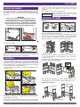
Working from the outside of one ladder section, place your foot on
to the lowest rung. Take a firm hold of the top rung ends and raise
until the lock bolts click into position. Now take a firm hold of the
second rung ends and raise until they click also into position.
Repeat this with the top and second rung of the opposite section.
The top and second rungs create the end guardrails and also
house the stowed side guardrails.
Release one of the top set side rails by sliding the yellow lock
catch forward and raising it clear of the support bar. Swivel the
support bar 90 degrees as shown on page 5.
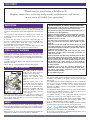
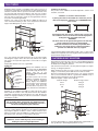
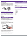
Stabiliser Positioning…
The position of the stabiliser should be adjusted to suit the work
situation, see below.
Depending upon the TeleTowers location, deploy the
stabilisers as shown in the illustration.
If placing the tower in the middle of a work area you are
advised to deploy the stabilisers at 135 DEGREES from
each corner.
If positioning the unit close to a wall or into a corner, the
two stabilisers closest to the wall should be deployed at
90 degrees and so parallel to the wall.
WARNING
The tower must not be positioned against a low wall that
cannot support the tower if it should topple.
Under NO circumstances should you position ANY
stabiliser at any angle where it cannot be locked in
position as it will NOT offer any support.
1m
61cm
33cm
If positioning the TeleTower® against a wall or into a corner set the
stabilisers as required, before moving the TeleTower® into its final
position and locking all castors.
Go to the opposite end and release the rail of the same height,
swivelling the support bar in the same way. Attach each yellow
lock catch to its respective support bar to form a full set of upper
guardrails.
Repeat this with the lower set of guardrails.
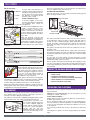
Stabilisers…
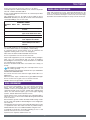
Deploy each stabiliser one at a
Retaining
time. Note that the MAXIMUM
Catch
permissible angle that the floor
surface may be is 0.5
DEGREES and this MUST NOT
UNLOCK
be exceeded.
Adjuster
Note that castors lock on to the
stabiliser assembly whenever
Stabiliser
Bar
the castor brake is engaged.
Bar Release Always deploy the stabilisers
‘one at a time’ as the respective
Lever
castor brake must be firstly
unlocked. Once in position, the
Foot
castor must be re-locked before
proceeding to the next stabiliser.
Working on one stabiliser assembly at a time, unlock the castor
brake, slide the retainer catch fully back and turn the stabiliser
assembly outward until at 135 degrees to the unit. Ensure the
retainer re-engages and that you lock the castor brake to hold the
assembly in position.
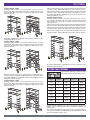
PLATFORM HEIGHT SELECTION
The TeleTower offers the user a choice of seven different platform
heights from 33cm to 2M. Selection of the platform height MUST
be made before fitting the platform.
Follow the instructions that cover the platform height you require
then go to ‘fitting the platform’.
When raising more than one rung to reach your required platform
height, you can where practicable raise two levels at a time.
Note that all ‘platform height instructions’ can only be followed
after you have fitted the full set of guard rails, NEVER set up a
platform without having first set up the guard rails.
Platform Heights of 33cm, 61cm and 1m…
Platform Height
Platform rung position
33cm
Rung 9
61cm
Rung 8
1M
Rung 6
Note that the retainer catch is the only device retaining
the assembly. When disengaged, the stabiliser/castor
assembly is free to ‘drop down’ and therefore care must
be taken when deploying the stabilisers.
1m
Lower the stabiliser bar by pressing down on the adjuster until the
foot is in contact with the ground. You can make fine adjustment
by turning the adjuster clockwise to lower or anticlockwise to raise.
When you need to raise the stabiliser foot fully, press down on the
bar release lever, raise the foot then release the lever.
61cm
33cm
CAUTION
Stabilisers are for stabilising only, not for levelling or
making any form of height adjustment.
For these three heights, no further adjustment is required and you
may go directly to the ‘fitting the platform’ section.
6