1
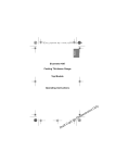
AL-832 USER MANUAL
AL-832 Wiring Diagram
AL-832 Side View
Operations: (The wireless door sensor function is being added in the
system)
1. Encoding method: press the encoding button(or press“
”+“
”
synchronously on a encoded remote control) for 3 seconds till LED
indication blinks and then release. Press any button on the remote
control for 3 seconds, LED indication remains 1 second and then
blinks continuously, this means encode successfully. (Other remote
controls can be encoded once, maximum 20 remote controls permitted.
If encode No.21, then No.1 will be disable). Press encoding button
again(or shortly press
”+“
” synchronously on a encoded remote
control) to exit, or the system will exit automatically if no operation in
20 second.
NOTE: If the inside 6 pin short-circuiter is being taken off, the
code learning function of mainframe is forbidden. For code
learning again, please insert the shot-circuiter.
2. Decoding method: press the encoding button for 6 seconds, LED
indication will blink from the 3rd seconds and turn off in 6 seconds,
this means decode successfully. Such operation will disable all
encoded remote controls.
3. Turn all the 4 DIP switches to “ON”, press “
”,YELLOW1 and
YELLOW2 connect for 1 second and then disconnect. Press
“
”,ORANGE1 and ORANGE2 connect for 1 second and then
disconnect. Press“
”,WHITE1 and WHITE2 connect 1 second and
then disconnect. Press“
”, PURPLE1 and PURPLE2 connect 1
second and then disconnect.
4. Turn all the 4 DIP switches to “OFF”, press “
and YELLOW2 connect, press“
disconnect. Press“
“
“
”again,YELLOW1 and YELLOW2
”,ORANGE1 and ORANGE2 connect, press
” again,ORANGE1
and
ORANGE2
”,WHITE1 and WHITE2 connect, press“
and WHITE2
disconnect. Press“
connect , Press“
”,YELLOW1
disconnect.
Press
” again, WHITE1
”, PURPLE1 and PURPLE2
”again, PURPLE1 and PURPLE2 disconnect.
5. Wire method & attention: When connecting with the outside siren,
please connect PINK2 with the positive pole of 12V input line of
mainframe, PINK1 connect with the positive pole of outside siren, the
negative pole of siren connect with BLACK(Ground). Green line is
the signal checking input line, when wiring, connect one port of the
wired accessories(e.g. wired door sensor), the other port connet with
BLACK.
The above wiring method is for 12V power. If the power is 24V,
PINK2 could not connect with positive pole of the 12V input line of
mainframe(if selecting 12V siren), it should be connected with an
outside 12V power, then connect the positive pole of 12V power with
PINK2, negative pole connect with BLACK, other lines is the same
method to connect as above.
Please see the PIC below: