
1
ReWaRD
Version 2.5
User Manual
RETAINING WALL DESIGN
2
ReWaRD 2.5 User Manual
Information in this document is subject to change without notice
and does not represent a commitment on the part of Geocentrix
Ltd. The software described in this document is furnished under a
licence agreement or non-disclosure agreement and may be used
or copied only in accordance with the terms of that agreement. It
is against the law to copy the software except as specifically
allowed in the licence or non-disclosure agreement. No part of this
manual may be reproduced or transmitted in any form or by any
means, electronic or mechanical, including photocopying and
recording, for any purpose, without the express written permission
of Geocentrix Ltd.
©1992-2000 Geocentrix Ltd. All rights reserved.
Geocentrix and ReWaRD are registered trademarks of Geocentrix
Ltd.
Frodingham and Larssen are registered trademarks of Corus plc in
the United Kingdom.
Microsoft and Windows are registered trademarks of Microsoft
Corporation. IBM is a registered trademark of International Business
Machines Corp. Other brand or product names are trademarks or
registered trademarks of their respective holders
Set in Optimum using Corel WordPerfect 8.0.
Service Release 3 (9/00).
Printed in the UK.
Acknowledgements
3
Acknowledgments
ReWaRD 2.5 was designed and written by Dr Andrew Bond and
Ian Spencer of Geocentrix Ltd. The program was originally
commissioned by British Steel Ltd.
The ReWaRD User Manual was written by Dr Andrew Bond.
Parts of ReWaRD were developed with the assistance of Professor
David Potts of Imperial College of Science, Technology, and
Medicine and Dr Hugh St John of the Geotechnical Consulting
Group.
The following people assisted with the testing of this and previous
versions of the program: Vassilis Poulopoulos (Geocentrix); Romain
Arnould (Geotechnical Consulting Group); Andy Fenlon (Nonsuch
Videographics); Joe Emmerson (British Steel); and Kieran Dineen
(Imperial College).
4
ReWaRD 2.5 User Manual
Table of contents
5
Table of contents
Acknowledgments . . . . . . . . . . . . . . . . . . . . . . . . . . . . . . . . . . . 3
Table of contents . . . . . . . . . . . . . . . . . . . . . . . . . . . . . . . . . . . . 5
Chapter 1
Introduction . . . . . . . . . . . . . . . . . . . . . . . . . . . . . . . . . . . . . . . 11
About this book
11
Conventions
12
Where to go for help
13
User manual
13
Reference manual
13
ReWaRD’s help system
13
Tooltips
13
Technical support
14
Sales and marketing information
14
Chapter 2
Installing and starting ReWaRD . . . . . . . . . . . . . . . . . . . . . . . 15
What’s in the ReWaRD package
15
Hardware and software requirements
15
Upgrading from an earlier version of ReWaRD
16
To install ReWaRD
16
To run ReWaRD
17
To uninstall ReWaRD
17
Chapter 3
Overview . . . . . . . . . . . . . . . . . . . . . . . . . . . . . . . . . . . . . . . . . 19
Key features
19
The Desktop
19
Title Bar
20
Menu Bar
20
Toolbar
20
Main work area
21
Status Bar
21
6
ReWaRD 2.5 User Manual
The Stockyard
Workbooks
Tools
Startup-Wizard
Construction Wizard
Electronic Piling Handbook
On-line help
To open ReWaRD’s on-line help
21
22
23
24
24
25
25
26
Chapter 4
Tutorial 1 – cantilever wall in sand . . . . . . . . . . . . . . . . . . . . . 27
Worked example
27
Using the Construction Wizard to create a new project
27
Step 1
28
Step 2
29
Step 3
29
Step 4
30
Step 5
30
Step 6
31
What the Construction Wizard has done for you
32
Choosing a design standard
33
Designing to BS 8002
33
Calculating structural forces
35
Checking the required embedment
38
Designing to CIRIA 104
39
Calculating structural forces
40
Checking the required embedment
42
Conclusion
43
What next?
44
Chapter 5
Tutorial 2 – propped wall in stiff clay . . . . . . . . . . . . . . . . . . . 45
Worked example
45
Creating a new project from scratch
46
Creating a construction stage
46
Creating the ground geometry
47
Creating the wall
49
Creating a soil column
50
Adding the remaining objects
52
Table of contents
7
Designing to CIRIA 104
Calculating the required embedment
Calculating structural forces
Printing your results
What next?
54
55
56
58
60
Chapter 6
Tutorial 3 – cofferdam in mixed soils . . . . . . . . . . . . . . . . . . . 61
Worked example
61
Using the Construction Wizard to create a new project
62
Step 1 – specify the finished geometry
62
Step 2 – enter the depths of the props
62
Step 3 – enter the properties of the predominant soil type
63
Step 4 – choose the type of retaining wall
63
Step 5 – where do you want water tables?
63
Step 6 – go!
63
Modifying the project
64
Changing the depths of the excavations
65
Adding the missing soils
65
Adding the missing layers
67
Amending the borehole
68
Extending the wall and moving the top prop
69
Changing and adding water tables
70
Adding a surcharge
71
Designing the cofferdam: Stage 2
73
Selecting the design standard
73
Calculating earth pressures
74
Calculating required embedment
77
Calculating structural forces
78
Calculating displacements
79
Reviewing messages
81
Designing the cofferdam: other stages
81
What next?
82
Chapter 7
The Stockyard . . . . . . . . . . . . . . . . . . . . . . . . . . . . . . . . . . . . . 83
Object types
84
To create a new object
84
8
ReWaRD 2.5 User Manual
Existing objects
85
To choose which objects appear in the Existing Objects pane
85
To edit an existing object
85
Properties pane
86
Property boxes
86
Identifying icons
87
Objects names
88
Defaults
88
Context-sensitive help
89
Data validation
90
Chapter 8
Workbooks . . . . . . . . . . . . . . . . . . . . . . . . . . . . . . . . . . . . . . . . 93
The Drawing Board
94
Drag ‘n’ drop design
94
To select an object
94
To add an object to a Drawing Board
95
To remove an object from a Drawing Board
96
Editing an object
96
Changing the scale
97
Results pages
97
Customizing a page
98
Choosing a layout
99
The Messages Page
99
Chapter 9
Producing reports . . . . . . . . . . . . . . . . . . . . . . . . . . . . . . . . . 101
Selecting what appears in a report
101
Stockyard page
101
Workbooks page
102
Results page
102
Layout page
103
Print preview
103
Printing
104
Chapter 10
Customizing the program . . . . . . . . . . . . . . . . . . . . . . . . . . . 105
Table of contents
9
Windows’ Registry
Program-wide settings
Defaults for engineering objects
Factory defaults
105
105
106
106
Chapter 11
Upgrading from previous versions . . . . . . . . . . . . . . . . . . . . 109
What’s new or improved in ReWaRD 2.5
109
What’s new or improved in ReWaRD 2.0
110
10
ReWaRD 2.5 User Manual
Chapter 1: Introduction
11
Chapter 1
Introduction
Welcome to ReWaRD®, the advanced retaining wall design
program. ReWaRD gives you the power to design a wide range of
embedded retaining walls in a variety of soil types, under an
assortment of loading conditions.
ReWaRD is easy to learn and even easier to use. You’ll find all the
things you need to design a retaining wall are only a few mouse
clicks away and can be put together in moments. ReWaRD’s
calculations are fast and its visual display is rich in detail and
comprehensive in coverage.
This chapter of the ReWaRD User Manual outlines the contents of
this book, explains the conventions that are used herein, and tells
you what to do if you need help using the program.
About this book
This User Manual is divided into the following chapters:
Chapter 1
Chapter 2
Chapter 3
Chapter 4
Chapter 5
Chapter 6
Chapter 7
Chapter 8
Chapter 9
Chapter 10
Chapter 11
Introduction
Installing and starting ReWaRD
Overview
Tutorial 1 – cantilever wall in sand
Tutorial 2 – propped wall in stiff clay
Tutorial 3 – cofferdam in mixed soils
The Stockyard
Workbooks
Producing reports
Customizing the program
Upgrading from previous versions
12
ReWaRD 2.5 User Manual
Conventions
To help you locate and interpret information easily, the ReWaRD
User Manual uses the following typographical conventions.
This
Represents
Bold
Items on a menu or in a list-box; the text on a button or
next to an edit control; or the label of a group box
Item1 Y Item2
An item on a cascading menu. Item1 is the name of an
option on the main menu bar (such as File or Window);
and Item2 is the name of an option on the cascading
menu that appears when you select Item1 (such as New
or Open). Thus, File Y New represents the New
command from the File menu.
italic
Place holders for information you must provide. For
example, if you are asked to type filename, you should
type the actual name for a file instead of the word
shown in italics
Italic type also signals a new term. An explanation
immediately follows the italicized term
monospaced
Anything you must type on the keyboard
CAPITALS
Directory names, filenames, and acronyms
KEY1+KEY2
An instruction to press and hold down key 1 before
pressing key 2. For example, "ALT+ESC" means press and
hold down the ALT key before pressing the ESC key.
Then release both keys
KEY1, KEY2
An instruction to press and release key 1 before pressing
key 2. For example, "ALT, F" means press and release the
ALT key before pressing and releasing the F key
Chapter 1: Introduction
13
Where to go for help
Your first source of help and information should be the ReWaRD
manuals and the on-line help system.
User manual
The ReWaRD User Manual (this book) explains how to install and
use ReWaRD. It includes a n overview of the program, a tutorial,
and separate chapters giving detailed information about ReWaRD’s
Stockyard and Workbooks.
Reference manual
The ReWaRD Reference Manual gives detailed information about
the calculations ReWaRD performs. The manual assumes you have
a working knowledge of the geotechnical design of embedded
retaining walls.
ReWaRD’s help system
ReWaRD’s help system contains detailed information about the
program. Help appears in a separate window with its own controls.
Help topics that explain how to accomplish a task appear in
windows that you can leave displayed while you follow the
procedure.
To open the help system:
Press F1
Click the Help button in any dialog box
Choose a command from the Help menu
If you need assistance with using on-line help, choose the How To
Use Help command from the Help menu.
Tooltips
If you pause while passing the mouse pointer over an object, such
as a toolbar button, ReWaRD displays the name of that object. This
feature, called tooltips, makes it easier for you to identify what you
see and to find what you need.
14
ReWaRD 2.5 User Manual
Technical support
Technical support for ReWaRD is available direct from Geocentrix
or through your local distributor. If you require technical support,
please contact Geocentrix by any of these means:
Voice: +44 (0)1737 373963
Fax: +44 (0)1737 373980
E-mail: [email protected]
Web: www.geocentrix.co.uk
Please be at your computer and have your licence number ready
when you call.
Alternatively, you can write to the following address:
ReWaRD Technical Support
Geocentrix Ltd
Scenic House
54 Wilmot Way
Banstead
Surrey
SM7 2PY
United Kingdom
Please quote your licence number on all correspondence.
Sales and marketing information
For sales and marketing information about ReWaRD, please contact
ReWaRD Sales on the same numbers as above.
Chapter 2: Installing and starting ReWaRD
15
Chapter 2
Installing and starting ReWaRD
ReWaRD can be installed to run on Windows 95 or Windows NT.
Although you can install the software on as many computers as you
like, you will only be able to run the program on those computers
to which you attach the supplied security key.
Before you begin installing your copy of ReWaRD, there are a few
things you should check:
Examine the contents of your ReWaRD package to check we
have sent you everything listed below
Make sure you have the necessary hardware and software to
run ReWaRD
What’s in the ReWaRD package
The ReWaRD package includes the following items:
ReWaRD User Manual (this document)
ReWaRD Reference Manual
Geocentrix Software CD
One security key (dongle) for each copy of the program you
have purchased
Instructions for installing and running your copy of ReWaRD
Hardware and software requirements
In order to run ReWaRD, you will need the following hardware and
software:
IBM®-compatible PC with an 80386- (or higher) processor
Microsoft® Windows® 95 (or later) or Microsoft Windows NT
4 (or later)
At least 30Mb free space on your hard disk for a complete
installation
CD-ROM drive
Any printer supported by Windows
A mouse or other pointing device supported by Windows
16
ReWaRD 2.5 User Manual
Upgrading from an earlier version of ReWaRD
If you are upgrading your copy of ReWaRD from an earlier version,
you should note the following:
ReWaRD’s setup program installs Version 2.5 in a different
directory to Versions 1.x and 2.0 and hence will not overwrite
your existing copy of ReWaRD
JOB files created in ReWaRD 1.x can be imported into ReWaRD
2.5, where they will be converted into ReWaRD’s new RWD
format
RWD files created in ReWaRD 2.0 can be opened in ReWaRD
2.5, where they will be updated without loss of information
Documents created in ReWaRD 2.5 can be exported into
ReWaRD 1.x’s JOB format, although some information may be
lost. The program will inform you when this happens
Documents created in ReWaRD 2.5 cannot be read by
ReWaRD 2.0
To install ReWaRD
1. Connect the supplied security key to your computer’s parallel
(printer) port
2. Insert the Geocentrix Software CD into your CD-ROM drive.
The Geocentrix Software Installation program should
automatically appear on your screen (if not, run SETUP.EXE from
the root directory of the CD)
3. Click on the ReWaRD icon to go to the ReWaRD page
Chapter 2: Installing and starting ReWaRD
17
4. Click on the top icon to install the full version of ReWaRD
5. Follow the instructions on-screen
To run ReWaRD
1. From Windows’ Start menu, click Programs | Geocentrix
ReWaRD | ReWaRD 2.5.
To uninstall ReWaRD
1. Exit ReWaRD
2. Double-click on Add/Remove Programs in Windows’ Control
Panel
3. Select ReWaRD and click Add/Remove...
4. Follow the instructions on-screen
18
ReWaRD 2.5 User Manual
Chapter 3: Overview
19
Chapter 3
Overview
This chapter gives you an overview of ReWaRD’s main features.
Key features
ReWaRD’s user interface revolves around two main views:
The Stockyard, where you create, edit, and delete engineering
objects
Workbooks, where you define stages in the construction
sequence and perform engineering calculations
In addition, ReWaRD has a number of tools and features which
assist you in getting the best out of the Stockyard/Workbook
interface:
Wizards are provided to speed up frequently-performed tasks,
such as creating a multi-propped construction sequence
Context-sensitive dialog boxes and property sheets help to
simplify data-entry
Data-validation prevents you from entering invalid parameters
or choosing invalid options
On-line help is provided at the click of a button
The Desktop
ReWaRD’s Desktop comprises the program’s title bar, menu bar,
toolbar, main work area, and status bar.
20
ReWaRD 2.5 User Manual
Title Bar
The Title Bar displays the name and version number of the program.
The Control menu at the left-hand edge of the Title Bar provides
commands for sizing, moving, or closing ReWaRD’s main window.
The row of buttons at the right-hand edge of the Title Bar provide
quick ways of maximizing or minimizing and closing ReWaRD’s
main window.
Menu Bar
The Menu Bar provides groups of commands for manipulating files,
editing and viewing objects, setting properties, choosing a design
standard, performing calculations, running tools, arranging
windows, and accessing on-line help.
Some items (File, Edit, View, Design, Tools, Window, and Help)
appear on the Menu Bar at all times. Others (such as Create,
Properties, and Calculate) appear when needed, depending on
which view is active.
Toolbar
The Toolbar provides buttons that help you perform certain tasks
quickly, without using the menus. The Toolbar changes when you
change the active view.
If you pause while passing the mouse pointer over a toolbar button,
ReWaRD displays the name of that button. This makes it easier for
Chapter 3: Overview
21
you to recall what each button does.
Main work area
The Desktop’s main work area acts as a container for ReWaRD’s
Stockyard and Workbook views. When you create a new
document or open an existing document, ReWaRD creates a
Stockyard view for that document. You may then display as many
Workbook views as you wish, subject only to the limits of your
computer’s memory.
Status Bar
The Status Bar displays summary information about the current
document. The Status Bar changes when you change the active
view. For example, when a Workbook’s Drawing Board is selected,
the Status Bar displays the (x, y) co-ordinate of the mouse pointer,
which allows you to determine the location of any object on the
Drawing Board.
When you select a menu command, the Status Bar displays a brief
description of that command.
The Stockyard
ReWaRD’s Stockyard is where you create and manage the
engineering objects you will need to define your retaining wall
project. This is at the heart of ReWaRD’s data entry system.
22
ReWaRD 2.5 User Manual
The Stockyard is divided into three panes which list the engineering
objects you can create, the engineering objects you have already
created, and the properties of those objects. Context-sensitive popup menus allow you to manipulate each object at the click of a
button.
Chapter 7 describes the features of the Stockyard in detail and
explains how you can use it to maximum effect in your design
work.
Workbooks
Although the Stockyard is where you create the engineering objects
you need, ReWaRD’s Workbooks are where you use them to
create designs. Each Workbook encapsulates all the information
that is relevant to a particular construction stage, whether it is part
Chapter 3: Overview
23
of a sequence of stages or one of several “what-if” scenarios.
ReWaRD’s Workbooks are multi-paged windows containing a
Drawing Board, several results and graph pages, and a messages
page. The Drawing Board provides continuous visual feedback as
you build each construction stage. By presenting the results of its
calculations on separate pages, ReWaRD ensures that all the
information you might want is readily available without you being
overwhelmed with numbers.
Chapter 8 describes the capabilities of ReWaRD’s Workbooks in
detail and explains how you can use them to optimize your designs.
Tools
ReWaRD provides a number of tools to increase your efficiency in
using the program. You can see what tools are available to you by
clicking on the Tools item on the menu bar.
24
ReWaRD 2.5 User Manual
Startup-Wizard
The Start-up Wizard is designed to speed up your use of ReWaRD,
by listing the four most common tasks that users perform when
they first start the program.
Select which option you want from those provided and click the
Go button (alternatively, double-click on the desired option to
select and go in one action).
The Start-up Wizard automatically appears each time you run
ReWaRD. If you want to display the Start-up Wizard at any other
time, choose the Start-up Wizard command from the Tools menu.
Construction Wizard
The Construction Wizard helps you build up a multi-stage
construction sequence by answering a few key questions. Once the
Construction Wizard has built your multi-staged project, you can
then edit it to meet your precise requirements.
Chapter 3: Overview
25
The tutorial in Chapter 4 shows you how to use the Construction
Wizard.
To display the Construction Wizard, choose the Construction
Wizard command from the Tools menu.
Electronic Piling Handbook
ReWaRD comes bundled with an electronic version of the British
Steel Piling Handbook, 7th Edition (“the blue book”). This on-line
reference contains valuable information about sheet piling
products, their capabilities and availability, together with design
guidance for the Piling Handbook (i.e. nett pressure) method of
design.
On-line help
ReWaRD has one of the most comprehensive on-line help systems
of any geotechnical engineering program. If you want to know how
to use a particular dialog box or want to discover what BS 8002
recommends for angles of wall friction, you will find the information
you want in ReWaRD’s help system.
26
ReWaRD 2.5 User Manual
To open ReWaRD’s on-line help
To open ReWaRD’s on-line help:
Press F1
Click the Help button in a dialog box
Choose a command from the Help menu
Chapter 4: Tutorial 1 – cantilever wall in sand
27
Chapter 4
Tutorial 1 – cantilever wall in sand
This tutorial helps you to get started with ReWaRD, by designing a
simple cantilever wall in sand. The tutorial shows you how to:
Use ReWaRD’s Construction Wizard
Choose between the available design standards
View the results of your calculations
Worked example
The worked example involves the design of a wall to support a 4m
excavation in sand.
The ground conditions at the site comprise 15m of dense sand (E
1
= 17 kN/m³; k = 35ƒ; ck = 0) . The groundwater table is 15m below
excavation level and hence the sand can be considered dry
throughout.
A diaphragm wall 0.6m thick will be used to support the excavation
in the long term. No props can be used.
You are required to calculate the wall’s minimum depth of
embedment and the maximum bending moment and shear force
it must resist.
Using the Construction Wizard to create a new project
If ReWaRD is not already running, double-click on the ReWaRD
icon to load the program into your computer’s memory. Once the
“splash screen” has disappeared, ReWaRD displays its Start-up
Wizard.
1
E = unsaturated unit weight; k = angle of shearing resistance; and
ck = effective cohesion of the sand
28
ReWaRD 2.5 User Manual
Select the option Run the Construction Wizard and click the Go
button. ReWaRD’s Construction Wizard appears on your screen.
The Construction Wizard asks you a number of questions about the
retaining wall project you want to create and then generates a
project according to your answers.
Step 1
In Step 1, the Construction Wizard asks you to specify the finished
geometry of the retaining structure.
If not already selected, click on the Cantilever option. The number
of props changes to 0 and the picture shows a cantilever wall.
Change the retained height to 4m and click Next to continue.
Chapter 4: Tutorial 1 – cantilever wall in sand
29
Step 2
In Step 2, the Construction Wizard asks you to enter the depths of
the props. Since there are no props in this worked example, click
Next to continue.
Step 3
In Step 3, the Construction Wizard asks you to enter the properties
of the predominant soil type.
Select Sand from the Soil Type box; leave the wet density at its
default value; and enter a dry density of 1733 kg/m³ (which is
equivalent to 17 kN/m³) and an angle of friction of 35ƒ.
Although not shown, the Construction Wizard automatically sets
the soil’s effective cohesion to zero. (It doesn’t matter what value
30
ReWaRD 2.5 User Manual
you enter for the wet density, since this will not be used in this
example.)
Click Next to continue.
Step 4
In Step 4, the Construction Wizard asks you to choose the type of
retaining wall you want to use.
If it is not already selected, select Diaphragm from the Wall Type
box and 600 mm in the Width box. Click Next to continue.
Step 5
In Step 5, the Construction Wizard asks you on which side of the
wall you want water tables.
Chapter 4: Tutorial 1 – cantilever wall in sand
31
Select Neither Side and click Next to continue.
Step 6
Step 6 is where you instruct the Construction Wizard to generate
your project. If you want to review the information you have
entered in Steps 1-5, you can do so by clicking on the Previous and
Next buttons in succession.
When you are ready, click on Go to generate the project.
The Construction Wizard creates the engineering objects needed
to define the project, fills its Stockyard with these objects, and then
displays the Workbook associated with Construction Stage 1. At
this moment, your screen should look something like this:
32
ReWaRD 2.5 User Manual
What the Construction Wizard has done for you
ReWaRD’s Construction Wizard has automated a lot of the tasks
you would normally have to perform to setup a retaining wall
project from scratch. It has created a total of seven engineering
objects, which you can view by clicking on All Objects in the
Stockyard’s Objects Type pane:
Horizontal ground surface
Diaphragm wall 0.6m thick
Sand with appropriate properties
Drained layer containing the sand
Borehole containing the layer
Construction stage containing all the other objects
Horizontal excavation at 4m depth
You can review the properties of these obejcts by clicking on them
in turn and looking at the pane labelled Properties of Selected
Object.
At this point, it is a good idea to save your work, which you can do
by choosing the Save As command from the File menu (or by
Chapter 4: Tutorial 1 – cantilever wall in sand
33
clicking on the Save button on the Toolbar). When the Save As
dialog box appears, choose the folder where you want to save the
document, enter its filename as TUTORIAL1, and click OK
(ReWaRD will automatically add the extension .RWD for you).
Provided you installed ReWaRD in its default folder, you will find a
copy of this worked example in its current state in the folder
PROGRAM FILES\GEOCENTRIX\REWARD2\TUTORIAL 1, under
the name STEP1.RWD.
Choosing a design standard
ReWaRD provides support for several UK and
i n t e r n a t i o n a l
d e s i g n
standards, as listed on the Design menu.
When you select one of these standards,
ReWaRD changes its configuration so that the
calculations you perform are in accordance
with it.
In this Tutorial, you will prepare calculations
using two British design standards:
BS 8002
CIRIA 104
Designing to BS 8002
If it is not already selected, select BS 8002 from ReWaRD’s Design
menu. (The selected standard is shown ticked and greyed on this
menu.)
You can review the settings for the selected standard by choosing
the Properties... command from the Design menu. The following
box appears for BS 8002:
34
ReWaRD 2.5 User Manual
Click on each of the tabs in turn to see what rules the program
follows when it performs its calculations. In particular, note the
partial factors that are applied to the soil’s drained parameters.
On the Equilibrium page, note that equilibrium conditions are set
to “At minimum safe embedment” (see the ReWaRD Reference
Manual for further information about what this means). The
significance of this will become apparent later in the tutorial.
Click Cancel to close this box when you have finished.
Chapter 4: Tutorial 1 – cantilever wall in sand
35
Calculating structural forces
Once you have defined a valid construction stage and have
selected the design standard you wish to use, you are ready to
calculate structural forces in the wall:
If necessary, click on the Workbook to
make it active
Choose the Structural Forces
command on the Workbook’s
Calculate menu
(Or) Click on the Calculate Structural
Forces button on the Workbook’s
Toolbar
ReWaRD calculates earth pressures against
the wall that are in equilibrium and match
the condition given on the Equilibrium
page of the Design Standard’s property
box. In this case, earth pressures are
calculated at the minimum safe
embedment of the wall (i.e. in equilibrium with safety factors
applied).
ReWaRD then uses these earth pressures to calculate the structural
forces in the wall (see the ReWaRD Reference Manual for further
details) and displays the structural forces on a picture of the
construction stage.
36
ReWaRD 2.5 User Manual
Bending moments are shown by a dark blue solid line and shear
forces by a light blue dashed line. Maximum values of each are
noted on the diagram (these are design values – i.e. they already
include appropriate safety factors, which in the case of BS 8002 are
1.0). The dashed red line on the right hand side of the picture
indicates the unplanned excavation that ReWaRD has applied in
accordance with BS 8002.
You can view the earth pressures used to calculate these structural
forces by choosing the appropriate command from the Workbook’s
View Y Earth Pressures menu. You should choose the At Minimum
Safe Embedment command (since these are the earth pressures
used in this case).
The following diagram show the earth pressures obtained at the
minimum safe embedment.
Chapter 4: Tutorial 1 – cantilever wall in sand
37
Note that the earth pressures on the excavated side of the wall do
not begin at formation level – this is because BS 8002 requires a
minimum unplanned excavation of 0.5m to be included in the
calculations. (One of ReWaRD’s key benefits is that important
details like this are automatically applied.)
ReWaRD also provides the results of the earth pressure calculations
in a table or spreadsheet. To view the earth pressures in this format,
choose Table from the Workbook’s View menu. By default,
ReWaRD displays the design pressures, as shown below.
38
ReWaRD 2.5 User Manual
Checking the required embedment
To calculate the required embedment of the wall, choose the
Required Embedment command from the Workbook’s Calculate
menu. The results are displayed in a hierarchical tree view. By
expanding some of the nodes (by clicking on the + signs), you can
easily obtain whatever information you require from the
calculations. For example, in the picture below, you can see that:
The wall (whose unplanned retained height is 4.5m) requires a
minimum toe depth of 8.1m
Partial factors of 1.2 have been applied to the soil’s coefficient
of shearing resistance (tan k) and effective cohesion (ck)
An unplanned excavation of 10% of the retained height or 0.5m
(whichever is the greater) has been applied
The overturning and restoring moments (402 kNm/m) are in
balance and hence the wall is in moment equilibrium
Chapter 4: Tutorial 1 – cantilever wall in sand
39
Designing to CIRIA 104
You can obtain corresponding results using CIRIA 104 simply by
changing the design standard and re-running the calculations:
Select CIRIA 104 Y Gross Pressure
Method from ReWaRD’s
Design menu
Note that ReWaRD has cleared the
previous results and invites you to calculate the required
embedment again
Review the settings for this standard by choosing the
Properties... command from the Design menu
On the Equilibrium page, note that the equilibrium conditions
are set to “At Failure” (see the ReWaRD Reference Manual for
further information about what this means)
On the CIRIA 104 page, make sure that the design approach is
set to Moderately Conservative and the Works to Permanent
(again, see the ReWaRD Reference Manual for further
40
ReWaRD 2.5 User Manual
information about these settings)
Choose OK to save the design standard settings
Provided you installed ReWaRD in its default folder, you will find a
copy of this worked example in its current state in the folder
PROGRAM FILES\GEOCENTRIX\REWARD2\TUTORIAL 1, under
the name STEP2.RWD.
Calculating structural forces
To calculate the structural forces in the wall:
If necessary, click on the Workbook to make it active
Choose the Structural Forces command on the Workbook’s
Calculate menu
(Or) Click on the Calculate Structural Forces button on the
Workbook’s Toolbar
ReWaRD then calculates the embedment of the wall at failure (i.e.
in equilibrium with no safety factors applied) and uses the earth
pressures at this embedment to calculate the structural forces in the
wall. (See the ReWaRD Reference Manual for further information.)
ReWaRD displays the structural forces pictorially:
Chapter 4: Tutorial 1 – cantilever wall in sand
41
The maximum bending moment in this case is 93 kNm/m and the
maximum shear force is 210 kN/m. These are design values – i.e.
they already include the appropriate safety factors (which in the
case of CIRIA 104 are 1.5).
You can view the earth pressures used to calculate these structural
forces by choosing the appropriate command from the Workbook’s
View Y Earth Pressures menu. You should choose the At Failure
command (since these are the earth pressures that CIRIA 104
recommends for calculating structural forces).
The following diagram shows the earth pressures obtained at
failure.
42
ReWaRD 2.5 User Manual
Note that the earth pressures on the excavated side of the wall do
begin at formation level – this is because CIRIA 104 does not
require a minimum unplanned excavation to be considered.
Checking the required embedment
To calculate the required embedment of the wall, choose the
Required Embedment command from the Workbook’s Calculate
menu. The results are displayed in a hierarchical tree view. By
expanding the appropriate nodes, you can can see that:
The wall (whose retained height is 4.0m) requires a minimum
toe depth of 7.9m
Partial factors of 1.5-2.0 have been applied to the resisting
effective pressures (i.e. passive pressures)
Partial factors of 1.5 have been applied to the resulting bending
moments and shear forces
The overturning and restoring moments (317 kNm/m) are in
balance and hence the wall is in moment equilibrium
Chapter 4: Tutorial 1 – cantilever wall in sand
43
Conclusion
The results obtained using two different design standards are
summarized below:
Result
BS 8002
CIRIA 104
Required embedment (m)
8.1
7.9
Maximum bending moment
(kNm/m)
166
129
Maximum shear force (kN/m)
255
262
BS 8002 is more conservative than CIRIA 104 for this worked
example, particularly in terms of bending moments. This is due
mainly to the provision in BS 8002 of an unplanned excavation of
0.5m.
44
ReWaRD 2.5 User Manual
What next?
Chapter 5 show you how to build a project from scratch, using
ReWaRD’s drag-and-drop design features, and how to produce a
printed report.
Chapter 6 takes you through the design of a more complicated
structure – a multi-propped cofferdam in mixed soils – using the
techniques introduced in Tutorials 1 and 2.
Chapter 5: Tutorial 2 – propped wall in stiff clay
45
Chapter 5
Tutorial 2 – propped wall in stiff clay
This tutorial helps you to extend your knowledge of ReWaRD, by
designing a propped wall in stiff clay. The tutorial shows you how
to:
Build a project from scratch, without using the Construction
Wizard
Drag engineering objects from the Stockyard and drop them
onto a Workbook’s Drawing Board
Switching between short- and long-term stages (and hence
drained and undrained calculations)
Obtaining a printout of your input and output data
Worked example
The worked example is taken from CIRIA Report 104, Design of
retaining walls embedded in stiff clays, by Padfield and Mair (1984).
Appendix C of that document includes calculations for propped
walls in stiff clay with and without seepage around the wall.
Example C.2 involves the design of a wall to support an 8m
excavation in stiff clay.
The ground conditions at the site comprise an unspecified thickness
2
of stiff clay (E = Es = 20 kN/m³; k = 25ƒ; ck = 0) . Groundwater is
at 1m below ground level on the retained side of the wall and at
1m below formation level on the excavated side.
The wall (type unspecified, but assumed herein to be secant piled)
will form part of the temporary works and is supported by a prop
at 2m below ground level.
You are required to calculate the wall’s minimum depth of
embedment; the maximum bending moment and shear force in the
wall; and the force in the prop.
2
E and Es = unsaturated and saturated unit weights, respectively; k
= angle of shearing resistance; and ck = effective cohesion of the clay
46
ReWaRD 2.5 User Manual
Creating a new project from scratch
If ReWaRD is not already running, double-click on the ReWaRD
icon to load the program into your computer’s memory. Once the
“splash screen” has disappeared, ReWaRD displays its Start-up
Wizard. Select the option Create a New Project and click the Go
button. ReWaRD’s Stockyard appears on your screen.
Many of the following tasks can be performed in any order you
choose.
Creating a construction stage
Start the new project by creating a Construction Stage. Choose
Construction Stage on the Stockyard’s Create menu and click the
OK button in the dialog box that appears.
ReWaRD creates a new Construction Stage and displays its
property box. Change the name of the stage to Example C2 and
click OK.
ReWaRD saves the stage and then opens a new Workbook for you
to add engineering objects to. At this point, your screen should
look something like this:
Chapter 5: Tutorial 2 – propped wall in stiff clay
47
Provided you installed ReWaRD in its default folder, you will find a
copy of this worked example in its current state in the folder
PROGRAM FILES\GEOCENTRIX\REWARD2\TUTORIAL 2, under
the name STEP1.RWD.
Creating the ground geometry
Now define the geometry of the problem by creating a ground
profile and an excavation. Click on the Stockyard to make it active.
Although you could create a ground
profile via the Stockyard’s
Create menu as before, instead use
one of the buttons on the Stockyard’s
Toolbar to do the same thing. You can
locate which button to use by moving
your mouse pointer over each button
in turn until you find one whose tool-tip reads Create ground profile
(see picture alongside).
When you click this button, the following box appears.
Choose Horizontal and click OK.
ReWaRD creates a new Horizontal Ground Profile and displays its
property box. Since there are no properties to set for this object,
just click OK to save it in the Stockyard.
To add the new ground profile to the construction stage:
48
ReWaRD 2.5 User Manual
Click on the words Ground Profile 1 in the Stockyard’s Existing
Objects pane and – holding the left mouse button down – drag
the object onto the Workbook’s Drawing Board
When you move your pointer over the Workbook, the cursor
should change from this:
to this:
When the cursor changes symbol, release your finger and the
ground profile will be added to the construction stage
Repeat these instructions for a horizontal excavation, but change
the depth of the excavation to 8m before OK-ing its property box.
Note, in the picture above, the control with an arrow pointing
downwards (to the left of the up-down spin buttons):
When the arrow points down
, the value entered in the lefthand box is considered a depth measured downwards from
ground level
When the arrow points up
, the value entered in the box is
considered to be a level measured upwards from Ordnance
Datum (you can set ordnance datum via the Ordnance Datum
command on the Properties menu)
If you click this button several times, you will see the value toggle
between a depth of 8m depth and a level of ^8m relative to
Ordnance Datum.
Chapter 5: Tutorial 2 – propped wall in stiff clay
49
When you have dragged Excavation 1 onto the Workbook’s
Drawing Board, your construction stage should look something like
this:
Provided you installed ReWaRD in its default folder, you will find a
copy of this worked example in its current state in the folder
PROGRAM FILES\GEOCENTRIX\REWARD2\TUTORIAL 2, under
the name STEP2.RWD.
Creating the wall
Although you could create the wall via the Stockyard’s Create
menu or Toolbar as before, instead try double-clicking on the words
Retaining Wall in the Stockyard’s Object Types pane. In the dialog
box that appears, select Secant Pile and choose OK.
ReWaRD creates a new Secant Pile Wall and displays its property
box. Change the wall’s toe depth to 20m and click OK to save the
new wall. Then drag the wall onto the Workbook’s Drawing Board.
50
ReWaRD 2.5 User Manual
Provided you installed ReWaRD in its default folder, you will find a
copy of this worked example in its current state in the folder
PROGRAM FILES\GEOCENTRIX\REWARD2\TUTORIAL 2, under
the name STEP3.RWD.
Creating a soil column
Now it is time to define the soil column at the site. This involves
creating three different objects:
A soil, to represent the properties of the stiff clay
A layer, to represent the geometry and drainage conditions of
that soil
A borehole, to represent the elevation and ordering of the layers
Although you could create the soil by using any of the methods
described above, you can speed up the creation
of objects still further by using one of the
Stockyard’s context menus, as follows:
Right-click on the word Soil in the Stockyard’s
Object Types pane
Choose the command New Y Clay from the
pop-up menu that appears
ReWaRD creates a new Clay Soil and displays its
property box. Then set the following properties:
On the General page, change the soil’s name
to “Stiff clay”
On the Classification page, change the soil’s
classification to Unclassified/Stiff
On the Density/Weight page, click on the Unit Weight button
(if not already selected) and then change the soil’s saturated and
3
unsaturated weights to 20 kN/m
On the Effective Stress page, change the soil’s angle of shearing
resistance to 25ƒ and its effective cohesion to zero (leave the
Peak flag set and Poisson’s ratio unchanged)
On the total stress page, change the soil’s undrained strength to
60 kPa. When you attempt to go to the Notes page, a warning
message will appear telling you that the soil parameter is out of
range (this being a stiff clay, ReWaRD expected you to enter a
Chapter 5: Tutorial 2 – propped wall in stiff clay
51
strength between 75 and 150 kPa). Answer Yes to confirm the
value you have entered
On the Notes page, enter any notes about this soil that you
want to keep for future reference
Finally, click on the OK button to confirm the soil’s properties
Now create an undrained layer in which to put the soil:
Right-click on the word Layer in the Stockyard’s Object Types
pane and choose New Y Undrained on the menu that appears
ReWaRD creates a new Undrained Layer and displays its
property box
On the Properties page, change the soil to “Stiff clay” and the
thickness to 30m
Click on the OK button to confirm the layer’s properties
Now create a borehole in which to put the layer:
Right-click on the word Borehole in the Stockyard’s Object
Types pane and choose New Y Borehole on the menu that
appears
ReWaRD creates a new Borehole and displays its property box
On the Layers page, select “Layer 1" in the Available box and
click on the button with a single arrow pointing to the right (–>).
The layer moves from the Available box to the Chosen box
Click on the OK button to confirm the borehole’s properties
Finally, drag the borehole onto the Workbook’s Drawing Board,
where it automatically appears on both sides of the wall.
52
ReWaRD 2.5 User Manual
The Drawing Board now looks something like this:
Note the appearance of the soil column:
The colour/pattern of the main part of the soil column
represents the soil (in this case a clay)
The colour/pattern of the corner piece represents the layer (in
this case undrained)
Provided you installed ReWaRD in its default folder, you will find a
copy of this worked example in its current state in the folder
PROGRAM FILES\GEOCENTRIX\REWARD2\TUTORIAL 2, under
the name STEP4.RWD.
Adding the remaining objects
The remaining objects for you to create are two water tables (on
either side of the wall) and a prop.
Chapter 5: Tutorial 2 – propped wall in stiff clay
53
To add the first water table:
Right-click on the words Water Table in the Stockyard’s Object
Types pane and choose New Y Linear Seepage on the menu
that appears
ReWaRD creates a new Linear Seepage Water Table and
displays its property box
On the Properties page, change the depth to 1m
Click on the OK button to confirm the water table’s properties
Drag the water table onto the Workbook’s Drawing Board,
making sure that you drop in on the retained side of the wall (if
you get this wrong, just drag the water table off the Drawing
Board and drop it back into the Stockyard)
To add the second water table, repeat the instructions given above
but change the depth to 9m and drop the water table on the
excavated side of the wall.
To add the prop:
Right-click on the word Prop in the Stockyard’s Object Types
pane and choose New Y Horizontal on the menu that appears
ReWaRD creates a new Horizontal Prop and displays its
property box
On the Dimensions page, change the depth to 2m
Click on the OK button to confirm the prop’s properties
Drag the prop onto the Workbook’s Drawing Board
The Drawing Board now looks something like this:
54
ReWaRD 2.5 User Manual
Provided you installed ReWaRD in its default folder, you will find a
copy of this worked example in its current state in the folder
PROGRAM FILES\GEOCENTRIX\REWARD2\TUTORIAL 2, under
the name STEP5.RWD.
Designing to CIRIA 104
Tutorial 1 discussed ReWaRD’s support for different UK and
international design standards, so we will not dwell on these
matters here. To select the appropriate design standard for this
worked example:
Select CIRIA 104 Y Gross Pressure Method from ReWaRD’s
Design menu
On the CIRIA 104 page, make sure that the design approach is
set to Moderately Conservative and set the Works to Temporary
(see the ReWaRD Reference Manual for further information)
Choose OK to save the settings
Chapter 5: Tutorial 2 – propped wall in stiff clay
55
Provided you installed ReWaRD in its default folder, you will find a
copy of this worked example in its current state in the folder
PROGRAM FILES\GEOCENTRIX\REWARD2\TUTORIAL 2, under
the name STEP6.RWD.
Calculating the required embedment
To calculate the required embedment of the wall:
Choose the Required Embedment command on the
Workbook’s Calculate menu
(Or) Click on the Calculate Required Embedment button on the
Workbook’s Toolbar
ReWaRD calculates the embedment of the wall with the
appropriate safety factors taken from CIRIA 104 and displays the
results in a tree view:
The minimum safe embedment for this wall is 15.5m, based on a
56
ReWaRD 2.5 User Manual
safety factor of 1.35 applied to the effective earth resistance (the
1.35 is obtained by interpolation between a value of 1.2 for k =
20ƒ and 1.5 for k = 30ƒ – the stiff clay in this example has k = 25ƒ).
CIRIA 104, on page 136, gives a depth of embedment of
approximately 7.5m for Fp = 1.35, making the toe depth 15.5m (as
given by ReWaRD).
Calculating structural forces
To calculate structural forces in the wall:
Choose the Structural Forces command on the Workbook’s
Calculate menu
(Or) Click on the Calculate Structural Forces button on the
Workbook’s Toolbar
ReWaRD calculates the embedment of the wall at failure (i.e. in
equilibrium with no safety factors applied) and uses the earth
pressures for this embedment to calculate the structural forces in
the wall. (See the ReWaRD Reference Manual for further
information.)
Chapter 5: Tutorial 2 – propped wall in stiff clay
57
The maximum bending moment in this case is 944 kNm/m and the
maximum shear force is 323 kN/m. These are design values – i.e.
they already include the appropriate safety factors (which in the
case of CIRIA 104 are 1.5).
If you switch to spreadsheet or table view, by choosing Table from
the Workbook’s View menu, you obtain the design prop force at
2m depth as 577 kN/m.
CIRIA 104, on page 137, gives the maximum unfactored bending
moment as 627 kNm/m (corresponding to a design value of 940
kNm/m); the maximum unfactored shear force as 216 kN/m
(corresponding to a design value of 324 kN/m); and the prop force
as 232 kN/m (corresponding to a design value of 580 kN/m with
a safety factor of 2.5). Thus CIRIA 104 and ReWaRD are in good
agreement on these values (the slight differences are due to
rounding errors in CIRIA 104's calculations).
58
ReWaRD 2.5 User Manual
Printing your results
At this point, you will want to obtain a hard copy of your result.
ReWaRD allows you to select exactly what you want to appear on
your printed output:
You select which objects in the Stockyard should be printed (by
default, all objects are selected)
You select which Workbooks should be printed (by default, no
Workbooks are selected)
You select which results should be printed (by default all results
for each selected Workbook are printed)
To override the default settings:
Choose the Page Setup command from ReWaRD’s File menu
or the Page Setup button on ReWaRD’s Toolbar. The following
box appears:
Tick the engineering objects whose properties you want to print
Un-tick those object you don’t want to print
Next, click on the Workbooks tab:
Chapter 5: Tutorial 2 – propped wall in stiff clay
59
Tick the stages for which you want to print results
Un-tick those for which you don’t want results
Next, click on the Results tab:
Tick the results you want to print
Un-tick those you don’t want to print
Finally, click the OK button to save your settings
To print the data:
Choose the Print... command from ReWaRD’s File menu or the
60
ReWaRD 2.5 User Manual
Print button on ReWaRD’s Toolbar
Select whatever print options you require and click the OK
button to begin printing
To can obtain a preview of the printed output:
Choose the Print Preview... command from ReWaRD’s File
menu or the Print button on ReWaRD’s Toolbar
A window similar to this appears:
What next?
Chapter 6 takes you through the design of a more complicated
structure – a multi-propped cofferdam in mixed soils – using the
techniques introduced in Tutorials 1 and 2.
Chapter 6: Tutorial 3 – cofferdam in mixed soils
61
Chapter 6
Tutorial 3 – cofferdam in mixed soils
This tutorial helps you to get to grips with ReWaRD’s more
advanced features, by building a multi-propped cofferdam in a
mixed soil profile. The tutorial shows you how to:
Change the engineering objects generated by ReWaRD’s
Construction Wizard
Add new engineering objects as needed
Choose between the available design standards
Check the results of your calculations
Customize the printed output
Worked example
The worked example is taken from CIRIA’s Special Publication 95,
The design and construction of sheet-piled cofferdams, by Williams
and Waite (1993). Appendix B of that document describes the
design of a sheet pile cofferdam used to support a sub-surface tank
in a mixed soil profile.
The ground conditions at the site comprise:
3
4m of sand and gravel (E = 18 and Es = 20.3kN/m³; k = 35ƒ; ck
= 0)
2.5m of firm clay (Es = 21kN/m³; Cu = 60kPa)
3m of silty sand (Es = 20.3kN/m³; k = 30ƒ; ck = 0)
2m of soft/firm clay (Es = 20kN/m³; Cu = 40kPa)
Medium coarse sand (Es = 20.3kN/m³; k = 35ƒ; ck = 0)
The cofferdam will be open for less than 3 months and open to full
excavation depth for no more than two weeks (hence a total stress
analysis is appropriate).
Ground water level is 2.5m below ground surface. Water pressures
in the medium coarse sand are sub-artesian, with a pressure head
3
E and Es = unsaturated and saturated unit weights, respectively; k
= angle of friction; ck = effective cohesion; and Cu = undrained strength
62
ReWaRD 2.5 User Manual
of 80kPa at the surface of the sand. A pumping system will be
installed to lower the water pressures in the medium coarse sand
by 80kPa throughout the depth of interest.
The permanent works are to be constructed on top of a base slab
at a depth of 8m. A 0.5m thick drainage layer is to be placed
beneath the base slab, so that the final formation is at a depth of
8.5m. The sheet piles will have an upstand of 1m.
The first frame will be installed at 0.5m above ground level and the
excavation taken down to 5m before installing the second frame.
The second frame will be installed at a depth of 4m and the
excavation taken down to 7.5m before installing the third frame.
The third frame will be installed at a depth of 6.5m.
The plan dimensions of the cofferdam are 17m by 12m.
Using the Construction Wizard to create a new project
If ReWaRD is not already running, double-click on the ReWaRD
icon to load the program into your computer’s memory. Once the
“splash screen” has disappeared, ReWaRD displays its Start-up
Wizard. Select the option Run the Construction Wizard and click
the Go button. ReWaRD’s Construction Wizard appears on your
screen.
The Construction Wizard asks you a number of questions about the
retaining wall project you want to create and then generates a
project according to your answers.
Step 1 – specify the finished geometry
Click on the Multi-propped option. The number of props changes
to 3 and the picture of the wall changes to a multi-propped wall.
Change the retained height to 8.5m and click Next to continue.
Step 2 – enter the depths of the props
You want to place the first prop at 0.5m above ground level, but (as
you will find if you attempt to do it) the Construction Wizard does
Chapter 6: Tutorial 3 – cofferdam in mixed soils
63
not allow you to enter negative depths. Therefore, we will have to
leave Prop 1 at ground level and change its depth later.
Select Prop 2 and change its depth to 4m, by entering 4 in the
Depth box and clicking the Apply button. Then select Prop 3 and
change its depth to 6.5m. Click Next to continue.
Step 3 – enter the properties of the predominant soil type
In this example, the sand and gravel and the medium coarse sand
have identical properties and hence it is appropriate to choose
them as the “predominant soil type”. You will add the other soils
later.
Select Sand from the Soil Type box and enter a wet density of
2069kg/m³ (which is equivalent to 20.3kN/m³), a dry density of
1766kg/m³ (18kN/m³), and an angle of friction of 35ƒ. (Although
not shown, the Construction Wizard automatically sets the soil’s
effective cohesion to zero.) Click Next to continue.
Step 4 – choose the type of retaining wall
If it is not already selected, select Sheet Pile from the Wall Type
box; select Larssen from the Range box; and 16W from the Section
box. Click Next to continue.
Step 5 – where do you want water tables?
If it is not already selected, select the Both Sides option and click
Next to continue.
Step 6 – go!
When you are ready, click on Go to generate the project. The
Construction Wizard creates a new document, fills its Stockyard
with the objects needed to create your project, and then generates
four construction stages and displays their associated Workbooks
on the right hand side of the Stockyard.
At this point, your screen should look something like this:
64
ReWaRD 2.5 User Manual
Before proceeding further, save your work as TUTORIAL3.
Provided you installed ReWaRD in its default folder, you will find a
copy of this worked example in its current state in the folder
PROGRAM FILES\GEOCENTRIX\REWARD2\TUTORIAL 3, under
the name STEP1.RWD.
Modifying the project
ReWaRD’s Construction Wizard has automated a lot of the work
you would normally have to do to create a multi-propped retaining
wall project, but it has still left you with some things you need to
change — and some you need to add — in order to model the
worked example given in CIRIA SP95:
The excavation depths must checked (and, if necessary,
changed)
Other soil layers must be added
The retaining wall must be given an upstand and the top prop
moved up 0.5m
Water tables must be moved and extra water tables added
A surcharge must be added
Chapter 6: Tutorial 3 – cofferdam in mixed soils
65
Changing the depths of the excavations
When it generated the project you are working on, ReWaRD’s
Construction Wizard created three excavations at depths 0.5m
below the level of each prop and a fourth at final formation level.
You want to change some of these depths to match those given in
CIRIA SP95.
To display a list of the excavations that the Construction Wizard has
created for you, click on Excavation in the Stockyard’s Object Types
pane. ReWaRD displays a list of the excavations in the Stockyard’s
Existing Objects pane.
Select Excavation 2 from the Existing Objects pane, right-click your
mouse to display this object’s context menu, and choose the
command Properties of Excavation 2 (Generated).... ReWaRD
displays the property sheet for Excavation 2.
On the Dimensions page, change the excavation’s depth to
5.0m
On the Plan Dimensions page, click on the Has Plan
Dimensions box and enter a length of 17m and breadth of 12m
Click OK to confirm the excavation’s properties
Now select Excavation 3 from the Existing Objects pane and repeat
the instructions given above, but change this excavation’s depth to
7.5m.
Finally, select Excavation 4 from the Existing Objects pane and
repeat the instructions given above (in this case there is no need to
change the excavation’s depth, since it is already 8.5m).
Provided you installed ReWaRD in its default folder, you will find a
copy of this worked example in its current state in the folder
PROGRAM FILES\GEOCENTRIX\REWARD2\TUTORIAL 3, under
the name STEP2.RWD.
Adding the missing soils
To model the ground conditions at the site, we must first create a
number of soils.
66
ReWaRD 2.5 User Manual
To display the soil that the Construction Wizard has already created
for you, click on Soil in the Stockyard’s Object Types pane.
Double-click on the soil to display its property sheet, then:
On the General page, change the soil’s name to “Sand and
gravel”
On the Classification page, leave the soil’s classification as
Unclassified/Unspecified
On the Density/Weight page, click on the Unit Weight button
(if not already selected) and then change the soil’s saturated
3
3
weight to 20.3 kN/m and its unsaturated weight to 18 kN/m .
Answer Yes to any warning messages asking you to confirm the
values entered
On the Effective Stress page, leave this soil’s angle of friction as
35ƒ and its effective cohesion as zero
On the Notes page, enter any notes about this soil that you
want to keep for future reference
Finally, click OK to confirm the soil’s properties
To create a new soil:
Right-click on Soil in the Objects Types pane
Choose New Y Clay on the pop-up menu that appears
ReWaRD displays a property sheet for the newly created soil
On the General page, change the soil’s name to “Firm clay”
On the Classification page, change its State to Firm
3
On the Density/Weight page, change both weights to 21 kN/m .
Answer Yes to any warning messages asking you to confirm the
values entered
On the Total Stress page, change the Undrained Strength to 60
kPa
Finally, click OK to confirm the soil’s proprties
Now create two other soils with the following properties:
Sand: name = “Silty sand”; class = Silty; saturated and
3
unsaturated unit weights = 20.3 kN/m ; angle of shearing
resistance = 30ƒ
Clay: name = “Soft/firm clay”; state = Soft; both weights = 20
3
kN/m ; angle of shearing resistance = 30ƒ; undrained strength
= 40 kPa
Chapter 6: Tutorial 3 – cofferdam in mixed soils
67
Finally, since the medium coarse sand has the same properties as
the sand and gravel, create this soil by duplicating the latter:
Select the sand and gravel in the Stockyard’s Existing Objects
pane
Choose the Duplicate command from the Edit menu
Double-click on the duplicate (which ReWaRD has named “Soil
1”) to display its property sheet
Change the soil’s name to “Medium coarse sand”
Click OK to confirm the soil’s properties
Provided you installed ReWaRD in its default folder, you will find a
copy of this worked example in its current state in the folder
PROGRAM FILES\GEOCENTRIX\REWARD2\TUTORIAL 3, under
the name STEP3.RWD.
Adding the missing layers
Now that all the necessary soils have been created, you can use
these to define the layers at the site.
To display the layer that the Construction Wizard has created for
you, click on Layer in the Stockyard’s Object Types pane. Doubleclick on the layer to display its property sheet, then:
On the General page, change the layer’s name to “Layer 1"
On the Properties page, change the layer’s thickness to 4m and
select “Sand and gravel” as the soil
Click OK to confirm the layer’s properties The soil columns on
the Drawing Board of each Workbook change to reflect the new
layer thickness
To create a new layer:
Right-click on Layer in the Stockyard’s Objects Types pane
Choose New Y Undrained on the pop-up menu that appears
ReWaRD displays a property sheet for the newly created layer
On the Properties page, change the layer’s thickness to 2.5m
and select “Firm clay” as the soil (note how ReWaRD only
displays those soils that can be treated as undrained)
Click OK to confirm the layer’s properties
68
ReWaRD 2.5 User Manual
Now create three other layers with the following properties:
Drained: thickness = 3m; soil =“Silty sand”
Undrained: thickness = 2m; soil = “Soft/firm clay”
Drained: thickness = 5m; soil = “Medium coarse sand”
Provided you installed ReWaRD in its default folder, you will find a
copy of this worked example in its current state in the folder
PROGRAM FILES\GEOCENTRIX\REWARD2\TUTORIAL 3, under
the name STEP4.RWD.
Amending the borehole
The Workbook’s Drawing Board displays two soil columns, one on
each side of the wall. ReWaRD’s Construction Wizard has placed
Borehole 1 (which currently contains Layer 1) in both of these soil
columns. By adding Layers 2 to 5 to Borehole 1, you will get the
same soil columns on both sides of the wall, not only in Stage 4,
but in all the stages where Borehole 1 is used.
To demonstrate this, select Layers 2 to 5 in turn and drag them
onto the Workbook’s Drawing Board for Stage 4. (To drag a layer,
click on its name in the Stockyard’s Existing Objects pane, hold the
mouse button down and then move the mouse pointer across to
the Workbook. The cursor will change shape from
to
as you do this.) When you let go of the mouse button, the layer
being dropped is added at the bottom of the borehole (so it is
important that you do this in the right order!).
Be careful not to drop the layer onto or above either of the soil
columns, since that will insert the layer into the appropriate
borehole rather than append the layer at the bottom of the
borehole. If you drop the layers on the middle of the Drawing
Board, they automatically appear at the bottom of the borehole.
If you make a mistake, you can drag a layer out of the borehole and
return it to the Stockyard in the same way.
Chapter 6: Tutorial 3 – cofferdam in mixed soils
69
When you have finished this, bring the Workbook for Stage 2 to the
front of the screen by clicking on it or by choosing Workbook:
Stage 2 (Generated) from ReWaRD’s Window menu. Note that the
soil columns for Stage 2 have been updated to correspond with
those for Stage 4.
Provided you installed ReWaRD in its default folder, you will find a
copy of this worked example in its current state in the folder
PROGRAM FILES\GEOCENTRIX\REWARD2\TUTORIAL 3, under
the name STEP5.RWD.
Extending the wall and moving the top prop
The next task is to provide the retaining wall with an upstand so
that the top prop can be placed at 0.5m above ground level.
To display the wall that the Construction Wizard has created for
you, click on Retaining Wall in the Stockyard’s Object Types pane.
Double-click on the wall to display its property sheet, then:
On the Dimensions page, change the wall’s height to 13.5m
(this is the height assumed in CIRIA SP95) and its upstand to
0.5m (so its total height is 14m)
Click OK to confirm the wall’s properties. The Drawing Boards
70
ReWaRD 2.5 User Manual
change to reflect the new wall dimensions
To display the props that the Construction Wizard has created for
you, click on Prop in the Stockyard’s Object Types pane. Doubleclick on Prop 1 to display its property sheet, then:
On the Dimensions page, change the props’s depth to –0.5m
Click OK to confirm the prop’s properties. The Drawing Boards
change to reflect the new prop position
Provided you installed ReWaRD in its default folder, you will find a
copy of this worked example in its current state in the folder
PROGRAM FILES\GEOCENTRIX\REWARD2\TUTORIAL 3, under
the name STEP6.RWD.
Changing and adding water tables
The next task is to model groundwater conditions at the site.
To display the water tables that the Construction Wizard has
created for you, click on Water Table in the Stockyard’s Object
Types pane.
Double-click on “Water Table 1" to display its property sheet, then:
On the Properties page, change the depth to 2.5m
Click OK to confirm the water table’s properties
Double-click on “Water Table 3" to display its property sheet, then:
On the Properties page, change the depth to 5.0m (to bring it
back into line with the changed excavation depth)
Click OK to confirm the water table’s properties
To create a new water table:
Right-click on Water table in the Stockyard’s Objects Types pane
Choose New Y Hydrostatic on the pop-up menu that appears
ReWaRD displays a property sheet for the newly created water
table
On the General page, change the water table’s name to “Subartesian water table”
Chapter 6: Tutorial 3 – cofferdam in mixed soils
71
On the Properties page, change the depth to 11.5m
On the Connectivity page, un-check the option Connected to
Overlying Water Tables and set the Ambient Pressure to 80kPa
Click OK to confirm the water table’s properties
Check that the Workbook for Stage 2 is still at the front of all the
other Workbooks. Then select the sub-artesian water table in the
Stockyard’s Objects Pane and drag it onto the Stage 2's Drawing
Board. (The cursor will change shape from
to
as you
do this.) When you let go of the mouse button, the water table
appears on whichever side of the wall you let go of the mouse
button. Repeat the exercise again, but drop the water table on the
other side of the wall.
Now duplicate the sub-artesian water table, by selecting it from the
Stockyard’s Objects Pane and choosing the Duplicate command
from the Edit menu. Then double-click on the duplicate (which
ReWaRD has named “Water Table 1”) to display its property sheet:
On the General page, change the water tables’s name to
“Pumped water table” (this water table will be used to replace
the sub-artesian water table from Stage 3 onwards)
On the Connectivity page, set the Ambient Pressure to 0kPa
Click OK to confirm the water table’s properties
Bring the Workbook for Stage 3 to the front of the other
Workbooks (by recourse to the Windows menu, if necessary) and
drag the pumped water table onto both sides of the wall. Change
the depth of Water Table 4 to 7.5m. Repeat for Stage 4.
Provided you installed ReWaRD in its default folder, you will find a
copy of this worked example in its current state in the folder
PROGRAM FILES\GEOCENTRIX\REWARD2\TUTORIAL 3, under
the name STEP7.RWD.
Adding a surcharge
The final task is to add a surcharge at the top of the wall.
To create a new surcharge:
72
ReWaRD 2.5 User Manual
Right-click on Surcharge in the Stockyard’s Objects Types pane
Choose New Y Uniform on the pop-up menu that appears
ReWaRD displays a property sheet for the newly created
surcharge
(If necessary) On the Loading page, change the surcharge type
to “HA Loading”
Click OK to confirm the surcharge’s properties
Now add the new surcharge to Stages 2-4 by choosing Tile from
ReWaRD’s Windows menu and then dragging the surcharge from
the Stockyard’s Existing Objects Pane and dropping it on the
Drawing Board for each stage in turn. (The cursor will change shape
from
to
as you do this.) Be sure to drop the surcharge
on the retained side of the wall.
Provided you installed ReWaRD in its default folder, you will find a
copy of this worked example in its current state in the folder
PROGRAM FILES\GEOCENTRIX\REWARD2\TUTORIAL 3, under
the name STEP8.RWD.
Chapter 6: Tutorial 3 – cofferdam in mixed soils
73
Designing the cofferdam: Stage 2
At this point, you are ready to start the design of the cofferdam.
You may find it easier to close all the open workbooks and then reopen that for Stage 2 only. (This will leave your screen less
cluttered.) To do this:
Choose the Close All Y Workbooks command from ReWaRD’s
Window menu
Choose Construction Stage from the Stockyard’s View menu
Right-click on Stage 2 in the Stockyard’s Objects Pane and
choose Open Workbook
Selecting the design standard
In this Tutorial, you will work to the recommendations given in
CIRIA Report 104, using the Gross Pressure Method. To select this
standard, choose the CIRIA 104 Y Gross Pressure Method
command from the Design menu.
You can review the settings for the selected standard by choosing
the Properties... command from ReWaRD’s Design menu. Click on
each of the tabs in turn to see what rules the program follows when
performing its calculations. When you reach the CIRIA 104 page,
74
ReWaRD 2.5 User Manual
select the Moderately Conservative design approach and
Temporary Works condition. When you have finished, click OK to
close the dialog box.
Provided you installed ReWaRD in its default folder, you will find a
copy of this worked example in its current state in the folder
PROGRAM FILES\GEOCENTRIX\REWARD2\TUTORIAL 3, under
the name STEP9.RWD.
Calculating earth pressures
The term “Earth pressures”, used in its generic sense, includes:
Pressures in the ground (vertical and horizontal effective stresses
and pore water pressures)
Pressures due to surcharges (vertical and horizontal)
Other pressures acting on the retaining wall (such as the
pressure from a water-filled tension crack)
ReWaRD calculates each of these “earth pressures” according to
well-established soil mechanics theory and automatically applies
any safety factors required by the selected design standard. Full
details of these calculations are given in the ReWaRD Reference
Manual.
To perform the calculations, select the Earth Pressures pop-out
menu from the Workbook’s Calculate menu (if necessary, click on
the Workbook first to activate it). ReWaRD lists the various earth
pressure conditions that it can calculate:
As built
At minimum safe embedment
With enhanced safety factors
At failure
Choose the All command to calculate all four “flavours” of earth
pressure.
ReWaRD displays the as built earth (red) and water (blue) pressures
acting on both sides of the wall, superimposed on a picture of the
construction stage.
Chapter 6: Tutorial 3 – cofferdam in mixed soils
75
Note how the earth and water pressures change with the various
layers in the ground. Note also how the passive earth pressures
drop to zero at formation level on the excavated side, owing to
CIRIA 104's required for a 1m softened zone.
You can view the earth pressures calculated for the other
conditions by choosing the appropriate command from the
Workbook’s View Y Earth Pressures menu. The following diagram
show the earth pressures obtained at the minimum safe
embedment.
76
ReWaRD 2.5 User Manual
ReWaRD also provides the results of the earth pressure calculations
in a table or spreadsheet. To view the results in this format, choose
the Table command from the Workbook’s View menu. ReWaRD
displays the design pressures, as shown below.
Chapter 6: Tutorial 3 – cofferdam in mixed soils
77
By default, ReWaRD displays the design pressures on the wall (see
the ReWaRD Reference Manual for further information.) You can
change what ReWaRD displays in the table by choosing one of the
commands on the bottom half of the View Y Earth Pressures fly-out
menu:
All
Coefficients
Soils Stresses
Surcharge Pressures
Design Pressures
Custom...
Calculating required embedment
To determine whether the ground offers sufficient passive
resistance to prevent the retaining wall from overturning, choose
the Required Embedment command from the Workbook’s
Calculate menu. ReWaRD displays detailed information pertaining
78
ReWaRD 2.5 User Manual
to the wall’s stability, in a hierarchical tree view. If you expand
various nodes (by clicking on the + signs) you get additional
information about the wall’s embedment, the safety factors used in
the calculations, the calculated overturning and restoring moments,
etc. The key piece of information in this view is the depth of the
wall toe at the minimum safe embedment, which in this case is
8.4m (as shown below).
See the ReWaRD Reference Manual for an explanation of what the
terms as built, at minimum safe embedment, with maximum safety
factors, and at failure mean.
Calculating structural forces
Structural forces include bending moments and shear forces acting
in the retaining wall and forces in any props or anchors used to
support it. Structural forces can only be calculated if the wall is in
a condition of stable equilibrium. ReWaRD automatically adjusts
the earth pressures acting on the wall in order to achieve
equilibrium before calculating the structural forces. Full details of
these calculations are given in the ReWaRD Reference Manual.
Chapter 6: Tutorial 3 – cofferdam in mixed soils
79
To calculate structural forces, choose the Structural Forces
command from the Workbook’s Calculate menu. ReWaRD displays
the structural forces diagram, which shows the bending moments
and shear forces acting on the wall. The maximum bending
moment and shear force are also given.
ReWaRD also provides the results of the structural forces
calculations in a table or spreadsheet. To view the results in this
format, choose the Table command from the Workbook’s View
menu.
Calculating displacements
ReWaRD calculates displacements using a database of measured
movements of existing walls, which has been incorporated into the
program. Full details of these calculations are given in the ReWaRD
Reference Manual.
To calculate displacements, choose the Displacements command
from the Workbook’s Calculate menu. ReWaRD displays a box
informing you that it generated 2 error/warning messages during
80
ReWaRD 2.5 User Manual
the calculations. If you inspect the Messages View and look under
the node labelled “Calculating displacements”, you will see that
ReWaRD cannot decide which profile to use to calculate
displacements. This is because the stratified nature of the ground
conditions makes it difficult for ReWaRD to select a predominant
soil type (i.e. sand, stiff clay, or soft clay).
To proceed, you need to tell ReWaRD which soil you consider
predominates. To do so, choose Options... from the Workbook’s
Calculate menu and select the Displacements page. Un-tick the
Auto-Select box, select Sand, and click the OK button.
This time, when you choose Displacements from the Workbook’s
Calculate menu, ReWaRD displays the following diagram. This is
a graphical view of the settlement and horizontal movement
envelopes predicted by the database. A summary of the maximum
settlement and horizontal movement (both average and upper and
lower bounds to the data) are also given.
Chapter 6: Tutorial 3 – cofferdam in mixed soils
81
Reviewing messages
ReWaRD provides an “audit trail” of the actions you take in each
Workbook, including:
A record of any objects added to or removed from the
construction stage
A record of the start and finish of any calculations you perform
Any warning or error messages generated by the calculations
To review these messages, choose the Messages command from
the Workbook’s View menu.
Designing the cofferdam: other stages
Designing the cofferdam involves repeating the calculations you
have performed for Stage 2 for the other stages in the construction
sequence. ReWaRD automatically adjusts its calculations to take
account of the number of props or anchors that are used to support
the retaining wall and any changes in ground conditions that you
specify.
82
ReWaRD 2.5 User Manual
What next?
Chapters 7 and 8 give more detailed information about ReWaRD’s
Stockyard and Workbooks. Here you will learn how to increase
your efficiency in using ReWaRD’s Integrated Design Environment.
When you have completed your design, you will want to obtain a
printout of your results. Chapter 9 gives instructions for customizing
ReWaRD’s printing capabilities.
Once you become familiar with ReWaRD’s capabilities, you will
doubtless want to customize its many options. Chapter 10 explains
how to do this.
Chapter 11 has some useful information for those users who have
upgraded to the current program from a previous version of
ReWaRD.
Chapter 7: The Stockyard
83
Chapter 7
The Stockyard
ReWaRD’s Stockyard allows you to create, edit, copy, paste, and
duplicate engineering objects with the greatest of ease.
The Stockyard is divided into three separate panes, showing the
Object Types (top left), Existing Objects (top tight), and Properties of
Selected Object (bottom). You can re-size each pane by dragging
the divider bars left and right or up and down when the cursor
changes to one of these symbols:
84
ReWaRD 2.5 User Manual
Object types
The Object Types pane lists all the engineering objects you can
create, ranging from ground profiles and excavations through to
surcharges and imposed loads. The Object Types pane provides
over 50 different engineering objects for you to use, each one
uniquely identified by an easy-to-follow full colour symbol.
When you click on one of the items listed in the Object Types
pane, the Existing Objects pane (see below) changes to show all
the existing objects of that type.
To create a new object
To create a new object:
Choose one of the commands on the
Stockyard’s Create menu (see the
picture alongside)
(Or) Right-click on an item in the Object
Types pane and choose the New Y
Object... command
(Or) Double-click on an item in the
Object Types pane
(Or) Click on one of the buttons on the
Stockyard’s Toolbar
In each case, a box will appear from which
you can choose which object to create.
Chapter 7: The Stockyard
85
Select the one you want and choose OK.
An alternative, and faster, way to achieve the
above is to:
Right-click on an item in the Object Types
pane, click on New, and then choose which
object to create from the fly-out menu that
appears (see the picture alongside)
Existing objects
The Existing Objects pane lists the engineering
objects you have created. ReWaRD allows you to create an
unlimited number of engineering objects.
When you click on one of the items listed in the Existing Objects
pane, the Properties pane (see below) changes to show summary
information for the selected object.
To choose which objects appear in the Existing Objects pane
To choose which objects appear in the Existing Objects pane:
Select one of the options on the Stockyard’s View menu
Click on an item in the Object Types pane
To edit an existing object
To edit the properties of an existing object:
86
ReWaRD 2.5 User Manual
Click on the object and then
choose the Properties of
<Name>... command on the
Stockyard’s Properties menu
(where <Name> is the name of
the object)
(Or) Right-click on the object
and choose the Properties of
<Name>... command on the
pop-up menu that appears (see
the picture alongside)
(Or) Double-click on the object
with the left mouse button
To cut, copy, paste, delete, duplicate, or move an existing object:
Click on the object and choose one of the commands on the
Stockyard’s Edit menu
(Or) Right-click on the object and choose one of the editing
commands on the pop-up menu that appears (see picture
above)
(Or) Click on the object and press one of the shortcut keys
(Ctrl+X to Cut, Ctrl+C to copy, Ctrl+V to paste, or Del to
delete)
(Or) Click on the object and then click on one of the editing
buttons (cut, copy, or paste) on the Stockyard’s Toolbar
If a command cannot be applied to the selected object (e.g. the
Move Up command is irrelevant to objects at the top of the Existing
Objects pane), it is disabled (and its menu command and toolbar
button are dimmed).
Properties pane
The Properties of Existing Object pane gives a brief summary of the
selected object’s properties. A scroll bar appears in the Properties
Pane if there is too much information to fit in the space available.
Property boxes
Whenever you create a new object or edit the properties of an
existing object, ReWaRD displays a property box so that you can
Chapter 7: The Stockyard
87
enter whatever information the program needs to define that
object. The property box “knows” what type of object you are
creating or editing and only asks you for information that is relevant
to that object. The following picture shows one of ReWaRD’s
object-oriented property boxes.
There are a number of features that are common to all of
ReWaRD’s property boxes. These include:
The object’s identifying icon, on the far left of the box
On the General page, an edit control for entering the name of
the object and some text indicating the type of object being
created/edited
One or more pages containing controls for entering the object’s
properties (e.g. in the picture above, Dimensions and Stiffness)
On the Notes page, space for entering notes about this object
for future reference
On the Defaults page, buttons to allow you to save and reset the
default settings in Windows’ Registry for this object type
OK and Cancel buttons
A Defaults button, which allows you to load the default settings
for this object type from Window’s Registry
A Help button for accessing the on-line help system
Identifying icons
Each one of ReWaRD’s 50+ engineering objects has a unique
identifying icon which is displayed in the top left hand corner of
that object’s property box. A smaller (simplified) version of the icon
88
ReWaRD 2.5 User Manual
is displayed in the Stockyard’s Objects Pane alongside the name of
the object and in the dialog box that appears when you create an
object of that type.
The icon helps you to identify each engineering object and (in its
larger form) indicates dimensions or other properties that are
needed to define that object. A selection of icons is shown below.
Objects names
Each engineering object has a unique name which is used to
identify it. ReWaRD automatically generates a default name (e.g.
Prop 1, Retaining Wall 3, etc.) When you create an engineering
object. You may change the name ReWaRD provides, provided
you use a name that is not being used by any another object in the
current document.
In practice, you will find it convenient to give certain objects (such
as surcharges) meaningful names (such as “Load from footing”,
“Traffic loading”, etc.).
Defaults
ReWaRD provides default properties for most of the parameters
Chapter 7: The Stockyard
89
that are needed to define your engineering objects. Chapter 9
explains how you can customize the default properties.
To change an object’s properties to its default values:
Click on the property box’s Defaults button
Press ALT-! on your keyboard
Context-sensitive help
To obtain context-sensitive help for a particular property box:
Click on the property box’s Help button
Press F1 on your keyboard
To find out what information you should enter into any particular
control within the property box, just move the mouse cursor over
that box withing the help topic, whereupon the cursor will change
to a hand. Click where the hand appears to display pop-up help for
90
ReWaRD 2.5 User Manual
that control.
Data validation
ReWaRD incorporates a comprehensive data-checking system that
prevents you from entering invalid information for any engineering
object. The data-checking system comprises:
A keyboard filter to prevent you from entering invalid characters
(such as entering a negative sign for a purely positive number)
A range check to prevent you entering numbers that are too
large (e.g. a wall length of 1000m) or too small (e.g. a wall length
of 0m)
A compatibility check to ensure that the values you enter are
consistent with the object’s other properties (e.g. a secant bored
pile must have a horizontal spacing less than its diameter)
A warning system to alert you to values that are unusually large
or small — but nevertheless may still be valid
When ReWaRD detects an invalid value for a particular property,
it displays an appropriate error message and won’t allow you to
continue until you have corrected the error.
When ReWaRD detects a value that is unusually large or small, it
displays an appropriate warning message and asks you to confirm
the value you have entered.
Chapter 7: The Stockyard
91
Choose Yes to confirm the value or No if you want to change it.
If you do not understand why a particular warning or error message
is being triggered, click on the property box’s Help button for
further information.
92
ReWaRD 2.5 User Manual
Chapter 8: Workbooks
93
Chapter 8
Workbooks
ReWaRD’s Workbooks can be used to define or display:
Separate stages in a construction sequence
Alternative construction scenarios
Different views of the same construction stage
Although each document can have only one Stockyard, it may have
an unlimited number of Workbooks on display at any one time.
Each Workbook comprises a number of pages, as follows:
The Drawing Board
Results pages (presented either graphically or as a table)
The Messages Page
94
ReWaRD 2.5 User Manual
You can display a particular page by:
Choosing one of the commands
on the Workbook’s View menu
Clicking on its tab at the bottom
of the Workbook
Clicking on any of the view
buttons on the Workbook’s
Toolbar (the third and fourth
rows of buttons in the picture
alongside)
The Drawing Board
The Drawing Board provides the main visual representation of a
construction stage. It also acts as a powerful editing screen, as
described in the section titled Drag ‘n’ drop design below.
The Drawing Board contains:
Draggable rulers attached to its left and top edges
Soil columns on either side of the wall
If you pause while passing the mouse pointer over a object
displayed on the Drawing Board, ReWaRD displays the name of
that object. This makes it easier for you to identify which object is
which. Further, if you select an object in the Drawing Board,
ReWaRD’s Stockyard automatically displays the properties of that
object for you to see.
Drag ‘n’ drop design
One of ReWaRD’s most powerful features is what we have termed
drag ‘n’ drop design. This is the ability to build up a construction
stage by dragging engineering objects from the Stockyard and
dropping them onto a Workbook’s Drawing Board. The Drawing
Board’s built-in intelligence ensures that your engineering objects
only go where it is possible for them to go.
To select an object
To select an engineering object:
Chapter 8: Workbooks
95
Click on the object with the left mouse button
(Or) Press the TAB key repeatedly until the object is highlighted
ReWaRD indicates which object is selected by placing handles (i.e.
small square rectangles) at its corners or ends.
The object that is selected when you click on one of the soils
columns depends on which keys are pressed at the time:
If the CTRL key is pressed, the layer is selected
If the SHIFT key is pressed, the soil is selected
If neither the CTRL or SHIFT keys are pressed, the borehole is
selected
To add an object to a Drawing Board
To add an object to a Drawing Board, click on it in the Stockyard’s
Existing Objects pane with the left mouse button and hold the
button down. The cursor will change to a circle with a line across
it. Then drag the mouse across to the Drawing Board and, when the
cursor changes to a symbol with a + sign, release the mouse button.
The cursor indicates the type of object you are dragging and where
you can drop it. For example:
signifies that the object (in this case, a retaining wall) can
be dropped at the current location
signifies that the object cannot be dropped at the current
location
What happens when you release the mouse button depends on
what type of object you are dragging and where you drop it:
Most objects automatically appear on the “correct” side of the
wall at their specified depths
Unless you drop them on one of the soil columns, layers are
added to the bottom of the boreholes on both sides of the wall
(i.e. underneath any existing layers)
If you drop a layer on a soil column, it appears immediately
below the layer on which you drop it
96
ReWaRD 2.5 User Manual
If you drop a layer above a soil column, it appears at ground
level
If you drop a soil onto an existing layer, the layer’s soil type
changes
Water tables appear on whichever side of the wall you drop
them on
To remove an object from a Drawing Board
To remove an object from a Drawing Board, click on it with the left
mouse button and hold the button down. Handles will appear to
indicate that the object is selected and the cursor will change to a
circle with a line across it. Then drag the mouse across to the
Stockyard’s Object’s Pane and, when the cursor changes to a
symbol representing the object, release the mouse button. The
object will disappear from the Drawing Board.
Editing an object
You can edit the properties of an existing object “in place” in a
number of ways:
By selecting the object and
choosing the Properties of
<Name>... command on the
Workbook’s Properties
menu (where <Name> is the
name of the object)
(Or) By selecting the object,
clicking the right-mouse
button, and choosing the
Properties of <Name>...
command on the pop-up
menu that appears (see the picture alongside)
(Or) By double-clicking on the object with the left mouse button
Similarly, you can edit (i.e. cut, copy, paste, or delete) an object:
By selecting the object and choosing one of the commands on
the Workbook’s Edit menu
(Or) By selecting the object, clicking the right-mouse button, and
choosing one of the editing commands on the pop-up menu
that appears (see the picture above)
Chapter 8: Workbooks
97
(Or) By selecting the object and pressing one of the shortcut
keys (Ctrl+X to Cut, Ctrl+C to copy, or Del to delete)
(Or) By selecting the object and then clicking one of the editing
buttons (cut or copy) on the Workbook’s Toolbar
Note that when you cut or delete an object from a Drawing Board,
it is only removed from the associated construction stage — it is not
cut or deleted from the Stockyard.
Changing the scale
You can change the scale of the drawing on the Drawing Board:
By choosing the Zoom In or Zoom Out
commands
on
the
Tools
menu and then clicking on the Drawing Board
to change the scale up or down a level
(Or) By clicking the Zoom In or Zoom Out
buttons on the Workbooks’ Toolbar and then
clicking on the Drawing Board to change the
scale up or down a level
(Or) By right-clicking on one of the rulers and
choosing the scale you want from those listed
on the pop-up menu that appears (see the
picture alongside)
When you choose one of the Zoom commands, ReWaRD goes
into Zoom mode and will continue to alter the scale each time you
click on the Drawing Board. You can cancel Zoom mode:
By choosing the Pointer command on the Tools menu
(Or) By clicking the Pointer button on the Workbooks’ Toolbar
Results pages
Each Workbook provides the results of your calculations on
separate pages to ensure you are not overwhelmed with
information. There are pages for:
Earth pressures
Required embedment
Structural forces
98
ReWaRD 2.5 User Manual
Peck’s envelopes
Displacements
Base stability
Some pages display their results in one of two ways: either as a
diagram or in a table of values.
You can switch between these views:
By toggling between the Picture and Table commands on the
Workbook’s View menu
(Or) By toggling between the Picture and Table buttons on the
Workbook’s Toolbar
Customizing a page
You can customize each page’s display by choosing the Page...
command on the Workbook’s Properties menu. This command is
also available on the pop-up menu that appears when you rightclick on a Workbook page.
Additionally, in the table-based pages, you can customize each
column’s display by choosing the Properties of Column <Letter>...
command on the Workbook’s Properties menu (where <Letter> is
the column’s letter, starting at A). This command is also available on
the pop-up menu that appears when you right-click on a table
column.
Chapter 8: Workbooks
99
Choosing a layout
You can change to any one of a number of pre-defined layouts for
ReWaRD’s table pages by choosing the appropriate command
from the Workbook’s View menu. For example, to display as-built
earth pressure coefficients:
First, calculate the earth pressures as built by choosing the Earth
Pressures Y As Built command from the Workbook’s Calculate
menu
Then, switch to table display by choosing the Table command
from the Workbook’s View menu
Finally, display the earth pressure coefficients by choosing the
Earth Pressures Y Coefficients command from the Workbook’s
View menu
You can also save the current layout for later re-use, by choosing
the Workbook Y Save Layout... command from the Workbook’s
Properties menu. You can then restore the layout by choosing the
Workbook Y Restore Layout... command. A selection of useful
layouts are supplied with the program in the folder PROGRAM
FILES\GEOCENTRIX\REWARD2\LAYOUTS (they have the file
extension .RWL).
You can restore a Workbook to its default layout by choosing the
Workbook Y Restore Default Layout command from the
Workbook’s Properties menu.
The Messages Page
ReWaRD uses the Messages Page to inform you of anything that
occurs in its calculations that requires your attention or approval.
100
ReWaRD 2.5 User Manual
The messages ReWaRD displays fall into three main categories:
Error messages, which explain why a particular calculation
cannot be performed
Warning messages, which explain what action ReWaRD has
taken in response to an unusual or unsafe condition
Informational messages, which provide additional information
about the calculations that is not available on any of the other
results pages
You can empty the messages window at any time by choosing the
Clear Messages command from the Workbook’s Calculate menu.
Chapter 9: Producing reports
101
Chapter 9
Producing reports
ReWaRD allows you to customize the information in its printed
reports, preview them on the screen before printing, and select
exactly which pages you want to print.
Selecting what appears in a report
What appears in ReWaRD’s printed reports depends on which
options are selected in the Page Setup box. To display this box:
Choose the Page Setup command on ReWaRD’s File menu
(Or) Click on the Page Setup button on the Toolbar
Each page within the Page Setup box covers a different part of the
report.
Stockyard page
The Stockyard page allows you to select which engineering objects
are included in the printed report (those which are ticked are
included, those which are not are omitted).
102
ReWaRD 2.5 User Manual
Workbooks page
The Workbooks page shows a list of all the Construction Stages
defined in the Stockyard. Each Construction Stage has a Workbook
associated with it, which contains the results of the calculations you
perform on that stage. For each Construction Stage you select on
the Workbooks page, ReWaRD prints the corresponding results
that are selected on the Results page (see below).
Results page
The Results page shows a list of all the calculations that you can
perform for a Construction Stage through its Workbook. For each
Stage you select on the Workbooks page (see above), ReWaRD
prints the results that you select on the Results page. To customize
the printout still further, select the specific components of these
results you want to print from the other pages that appear in the
Page Setup dialog box.
Chapter 9: Producing reports
103
Layout page
The Layout page allows you to customize the size of the margins
that appear around your report.
Print preview
To see a preview of what will be printed when you choose
ReWaRD’s Print command:
Choose the Print Preview command on ReWaRD’s File menu
(Or) Click on the Print Preview button on the Toolbar
The toolbar at the top of the print preview screen allows you to
scroll forwards and backwards through the report, zoom in or out
of the selected current page, view one or two pages at time, set the
printer up, and (when you are ready to proceed) print the report.
104
ReWaRD 2.5 User Manual
Printing
To print a report:
Choose the Print command on ReWaRD’s File menu
(Or) Click on the Print button on the Toolbar
The Print box that appears allows you choose which pages you
want to print, how many copies to print, whether to collate the
pages, etc.
Chapter 10: Customizing the program
105
Chapter 10
Customizing the program
This chapter gives a brief explanation of how you can customize
ReWaRD to suit your particular requirements. Further details can be
found in ReWaRD’s on-screen Help system.
Windows’ Registry
ReWaRD stores its default parameters in Windows’ Registry under
the key:
HKEY_LOCAL_MACHINE/SOFTWARE/Geocentrix/ReWaRD/2.5
Although you can edit these settings by hand if you wish, we
strongly recommend that you alter the program’s defaults via
various controls that are provided throughout ReWaRD.
Program-wide settings
You can change ReWaRD’s program-wide settings by choosing the
Preferences... command from the program’s Edit menu. When you
do so, the following box appears:
Change whichever settings you wish and click OK to confirm the
106
ReWaRD 2.5 User Manual
changes.
Settings given on the Advanced page should only be altered on the
advice of Geocentrix’s Technical Support team.
Defaults for engineering objects
When you edit any of the engineering objects that ReWaRD
provides, you can call up default parameters for that object by
clicking on the Defaults button on the right hand side of the
object’s property box. ReWaRD takes the default parameters from
the Registry and enters them onto whichever page of the property
box is visible (hidden pages are not affected). If a parameter does
not have a default setting in the Registry, ReWaRD uses its factory
default instead (see below).
You can set the default parameters for any engineering object by
going to its Defaults page and clicking the Set Defaults... button.
The properties of the object that you are currently editing are then
saved to the Registry for later recall.
You can reset the default parameters for any engineering object by
clicking the Reset Defaults... button on the same page. The values
stored in the Registry are replaced with factory defaults.
Factory defaults
ReWaRD contains within its program code default parameters for
Chapter 10: Customizing the program
107
all the engineering objects it provides. These default parameters are
called factory defaults and are fully documented in ReWaRD’s Help
system.
108
ReWaRD 2.5 User Manual
Chapter 11: Upgrading from previous versions
109
Chapter 11
Upgrading from previous versions
This chapter provides a brief summary of the new features you’ll
find in ReWaRD version 2.5.
What’s new or improved in ReWaRD 2.5
Version 2.5 has many new or improved features compared with
version 2.0:
Number of pre-built engineering objects increased to 51
Custom design standard greatly improved
Validation on calculation now reported via the Workbook’s
Messages page
Added earth pressure calculations at minimum safe embedment,
with maximum safety factors, and at failure
Wall friction, adhesion, undrained adhesion, and maximum
undrained adhesion can be customized
Improved implementation of the hinge method of calculating
structural forces
Added ability to specify object depths as height above
Ordnance Datum
Package includes British Steel’s Electronic Piling Handbook
Package includes British Steel’s Electronic Piling Case Studies
User and Reference Manuals provided in Adobe Acrobat format
Stockyard and Workbooks are now synchronized (so that
clicking on an object in the Workbook causes the Stockyard to
automatically display its properties)
Greatly improved Required Embedment, Base Stability, and
Messages pages
Added Durability calculation
Added conversions to/from any fundamental engineering unit
in the SI, CGS, or Imperial systems
Default settings now stored in Windows’ Registry and can be set
or reset via the program
Added Notes page to all engineering object property boxes
Added ability to save projects as templates
Added Preferences box
Added links to Geocentrix’s web site and software support web
pages
110
ReWaRD 2.5 User Manual
Improved the program’s overall look and feel, including many
user interface improvements
Several bug fixes and other improvements to the program’s
operation
Year 2000 compliance covering Levels 1-3 of the British
Standards Institution’s document DISC PD2000-1
32-bit application optimized for Windows 95/98/NT4
ReWaRD 2.5 can read files created in ReWaRD 2.0 with minor loss
of data (you will be informed when this occurs) and can import files
created in ReWaRD 1.x.
Neither ReWaRD 1.x nor ReWaRD 2.0 can read files created in
ReWaRD 2.5.
What’s new or improved in ReWaRD 2.0
Version 2.0 introduced many new or improved features compared
with version 1.x:
Major overhaul of ReWaRD’s user interface to make it quicker
and even easier to use
Completely new printing and graphing engines
Implemented the following official and de facto design
standards: Civil Engineering Code of Practice CP2; British Steel’s
Piling Handbook (6th Edition); CIRIA Report 104; Hong Kong
Geoguide 1 (2nd Edition); British Standard 8002; European preStandard ENV 1997 (Eurocode 7)
Added Print Preview and Page Setup commands
Added a recently-used file list to the File menu
Provided pre-built templates as a quick way of building common
design scenarios
Cut, Copy, and Paste commands added to the Edit menu,
allowing you to transfer engineering objects between different
ReWaRD documents and to transfer the results of your
calculations to any spreadsheet that can read Microsoft Excel
files
Start-up and Construction Wizards added to help novice users
get started and experienced users become more efficient in their
use of the program
Commands added to the Window menu to enable you to open,
close, minimize, and restore the various windows ReWaRD
Chapter 11: Upgrading from previous versions
111
creates
Introduced an integrated design environment, comprising the
Stockyard (see Chapter 7) and Workbooks (Chapter 8)
Added earth pressures calculations for king-post walls using
Broms’ method
Added structural force calculations for multi-propped walls using
the hinge method described in BS8002
Equilibrium conditions could be determined by any one of three
methods, using partial or lumped factors-of-safety
Radical overhaul of ReWaRD’s user interface
Project Information box moved to the Properties menu
Version 1.x’s “Information Managers” replaced by Version 2.0's
Stockyard. The Ground and Structure menus from Version 1.x
replaced by the Stockyard’s View and Create menus
The ability to change the value of gravity was removed
Version 1.x’s Earth Pressures, Factors-of-Safety, Bending
Moments, Prop Forces, and Displacements windows were
replaced by Version 2.0's Workbooks.
Various design options were brought together in Design
Standards
The results of base stability calculations were made available on
a separate page of each Workbook
Added automatic selection of Peck’s envelope
Added automatic selection of the displacement database
Graphs were made an integral part of the program
112
ReWaRD 2.5 User Manual


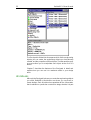
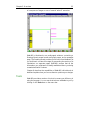
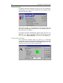


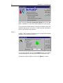
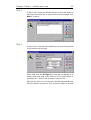
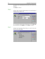
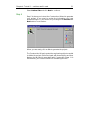
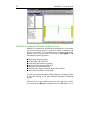
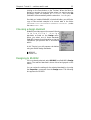
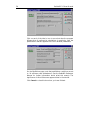
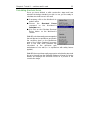
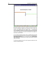
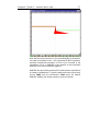
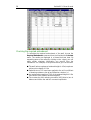
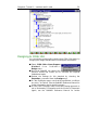
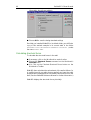
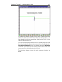
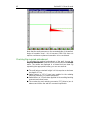
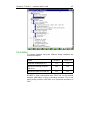


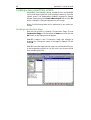
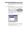
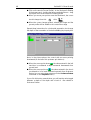
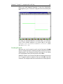
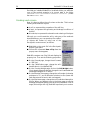
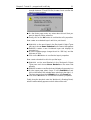
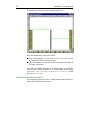

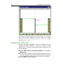
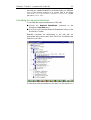

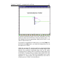
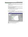
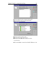
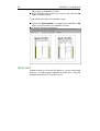

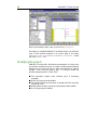

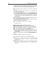


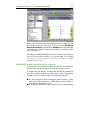

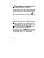
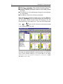
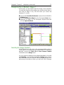

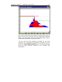

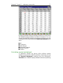
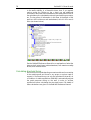
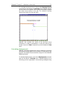
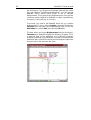
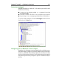

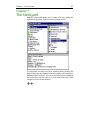
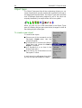
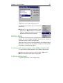
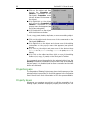
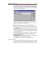

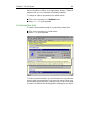


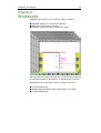
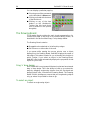

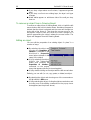
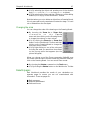
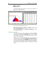

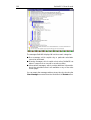
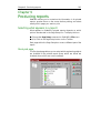
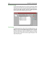

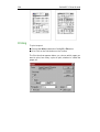
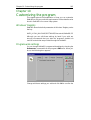


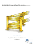


![Scheduler User Guide © Ecion.ca [ 1 ] Scheduler is a Windows](http://vs1.manualzilla.com/store/data/006858477_1-4414dd3fdf4d49d63a4f9c4ddcd871a4-150x150.png)