1
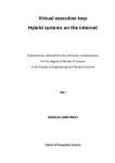
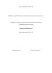
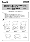
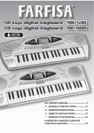
1
Progress Report on the Whisker Weaving All-Hexahedral
Meshing Algorithm*
Timothy J. Tautges
Scott A. Mitchell
Computational Mechanics and Visualization Dept,
Sandia National Laboratories, Albuquerque, NM 87185
ABSTRACT
In this paper, a review of the Spatial Twist Contiuum and the basic whisker weaving algorithm are given. Progress
in the detection and resolution of several types of degeneracies formed by whisker weaving are discussed. These
examples include so-called kniie doublets, triple doublets, through-cells and through-chords. Knife doublets and
triple doublets are resolved by preventing their formation a-priori, which forces whisker weaving to remove the
eleemnt(s) causing the degeneracy. Through-chordsand through-cells are left in the weave and resolved after the
weave has been closed. The paper concludes with three examples of geometries “closed” by whisker weaving.
INTRODUCTION
Automated meshing algorithms for general three-dimensional volumes can yield tetrahedral- or hexahedrd-shaped elements,
or a combinationof the two types. A fundamentaldifficulty of automatedmeshing is that a mesh is constrainedin terms of how
elements can share subfacetswith each other. This problem is much less constrainedfor tetrahedral or mixed element meshes,
hence tetrahedral and mixed elementmeshing algorithmshave received the most attention in the past. However, for applications
in non- linear structuralmechanics and other areas, there is a growing demand for all- hexahedral meshing algorithms.
Previous all-hexahedraJmeshing algorithmshave suffered shortcomingsin the principal areas of lack of automation,boundary
insensitivity (i.e. placing poorly shaped elements close to geometric boundaries), orientation sensitivity, and mesh size (i.e.
number of elements). For example, issoparametricmapping can be difficult to apply to very general geometriesin an automated
fashion [13. The refinement of a mapped mesh is also difficult, since it often means propagating the refinement in the three
parametric directions. Methods based on the finite octree approach can suffer from orientation sensitivity; these methods also
place the poorest-shapedelements near the boundary 123. The plastering algorithm, a three-dimensionalanalogue of the paving
algorithm [31, has difficulty combining the meshing fronts under the constraint of an all-hexahedralmesh [4].
whisker weaving is based on mesh dual information encapsulatedin the Spatial Twist Continuum [5][6].It builds the STC
representation of an all-hexahedral mesh using an advancing front method, starting with a geometry and an all-quadrilateral
surface mesh. whisker weaving simplifies the all- hexahedral meshing problem by fitst determining the connectivityof an allhex mesh without regard to its geometric embedding; thus, the most constrained part of the problem is solved first. An actual
hexahedral mesh is constructed from the STC by dualizing the STC into the connectivity of the hexahedral mesh, and then
iteratively smoothing to generate the geometric position of the mesh nodes 171.
This paper will summarize the recent progress on the whisker weaving algorithm. It will begin with a description of the STC
and the basic whisker weaving algorithm. Further details about the generation and removal of mesh degeneracieswill be
discussed. Some of the degenerate elements recently encountered in whisker weaving will be described, along with resolution
* This work was supported by the U.S. Department of Energy under contractDE-ACO4-76DOOO789,by the Applied
Mathematical Sciencesprogram, U.S. Department of Energy Research, and by Sandia National Laboratories Cooperative Research and Development Agreement SC93/01247 (USCAR Scientific Computing for Automotive Applications Partnership).
DISCLAIMER
This report was prepared as an account of work sponsored by an agency of the United States
Government. Neither the United States Government nor any agency thereof, nor any of their
employees, makes any warranty, express or implied, or assumes any legal liability or responsibility for the accuracy, completeness, or usefulness of any information, apparatus, product, or
process disclosed, or represents that its use would not infringe privately owned rights. Reference herein to any specific commercial product, process, or service by trade name, trademark,
manufacturer, or otherwise does not necessarily constitute or imply its endorsement, recommendation, or favoring by the United States Government or any agency thereof. The views
and opinions of authors expressed herein do not necessarily state or reflect those of the
United States Government or any agency thereof.
3
Portions of this document may be illegible
in electronic image products. Images are
pmduced from the best avaiiable original
document.
2
strategies.Thispresentation will conclude with examples of geometries closed to date with the whisker weaving algorithm, and
will discuss the future work planned to increase the robustness of the algorithm.
THE SPATIAL TWIST CONTINUUM
The whisker weaving algorithmworks in the geometric dual of an all-hexahedralmesh. It is easiest to visualize the dual for an
alreadyconsmcted mesh. Figure 1 shows a mesh consisting of threehexadedra. Also shown are dual entities for the
,
*
i
+
STC 2-cell
.
Figure 1.
STC Vertex
Geometric dual entities for an all-hexadedralmesh.
hexadedra, faces, edges, and nodes. The dual entities and their correspondingentities in mesh spaceare shown in Table 1.There
Table 1.Correspondence between mesh and STC entities.
is a direct comspondence between entities in the dual and entities in the primal (mesh). Therefore, mesh connectivity can be
constructed in the dual,and afterwards can be converted directly to the primal [7]
It can be seen from Figure 1that if adjacent STC %-cellsare combined, they form a general 3D surface which bisects hex
elementsin a given direction. These surfaces,referredto as whisker sheets, define a “sheet” of hexes, and their intersectionwith
the geometric boundary of the solid forms a loop of mesh faces. Also, adjacent STC edges can be joined end to end to form 3D
arcs; these are referred to as whisker chords. Whisker chords are formed by the intersection of two whisker sheets, and
correspond to columns of hex elements. Ha chord intersectsthe solid boundary, it does so in the middle of a face on the surface
mesh (some chords do not intersect the solid boundary, but form a closed loop inside the solid).
Since whisker sheets are topologically2-dimensional,they can be representedusing a 2D “whisker sheet” diagram; a collection
of whisker ShWE diagrams is shown in Figure 2, along with the geometry and surface grid they represent. For each sheet, the
outer loop of the polygon represents the intersection of the sheet with the geometricboundary. Each chord, indicated by a line
segment intersecting the outer loop, is labelled outsidethe loop by the face id where the loop enters the solid, and on the inside
of the loop with the ‘‘other‘’ sheet number of the two sheets which form the chord. Sinceeach chord is formed by the intersection
of two sheets, it is represented (in most cases) on two sheet diagrams. Vertices formed by the crossing of two chords represent
3
the STC vertices, which are the dual of hexahedra. Since hexes are formed by the intersection of three sheets, they are
represented on three sheet diagrams.
THE BASIC WHISKER WEAVING ALGORITHM
The initial conditions for whisker weaving are a geometric solid with an all-quadrilateralsurfacemesh. This informationis used
to find the initial face loops, which defme intersections of sheets with the boundary. It is assumed that each loop corresponds
to a unique sheet.For example, a cube geometry and surface mesh, and its initial collection of whisker sheets, are shown in
Figure 2.
1
Figure 2.
Brick geometry with 2x2 surface mesh (left), and initial sheets (right).
In its simplest form, the whisker weaving algorithm consists of three steps:
1.
Form a hex by crossing three chords on three sheets
Tbree chords are found by first selecting two chords that are adjacent on a given sheet, then looking for a third chord that is
adjacent to the first two on the other two sheets. The three chords are pairwise crossed, forming three STC vertices, which
represent the same hexahedral element. The first crossing for the example is shown in Figure 3
3
Figure 3.
2.
5
First crossing on three sheets, representing the first hex formed.
Resolve invalid connectivity
Step 1 is repeated until a case of invalid connectivity is detected. A natural part of the whisker weaving algorithm is the
formation and subsequent resolution of invalid connectivity. An example of the resolution of invalid connectivityis shown in
Figure 4. Here, a pair of faces shares two edges; this is represented in STC space by two chords being adjacent on two sheets
4
Figure 4.
Resolution of two faces sharing two edges by joining two chords.
(only the fmt sheet is shown in Figure 4). The resolution of this invalidity is simply to seam the two faces together; this is
equivalentto joining two chords into one. Sincejoining chords together removes two dangling STC edges from each of the two
sheets, this operation moves the algorithm towards completing the weave.
Steps 1and 2 are repeated until there are no dangling STC edges remaining on the sheets; the completedweave for the example
problem is shown in Figure 5. Note that this informationfully specifies the connectivity of the mesh; nodal positions must still
1
1
Figure 5.
Completed weave for the exampleproblem.
be determined. The final step in whisker weaving is to determine nodal positions using the primal construction algorithm [7].
The algorithm described in this section is sufficient for weaving relatively simple solids. For more complicatedgeometriesand
surface meshes, complications arise in the form of blind chords, self-intersecting sheets, and merged sheets. For a description
of these complications, see [51.
DEGENERACIES PRODUCED BY WHISKER WEAVING
whisker weaving produces degeneracies as a natural part of the meshing process. For example, the case of two faces sharing
two edges, described in the last section, is a degeneracy. Mesh degeneraciescan be resolved either immediately, or can be left
in the mesh to be resolved at a later time. In this section, examples of both types are given, along with the resolution technique
for each type.
Knife Doublet
Knife elements are formed when one face of a hexahedron is collapsed by joining two opposite nodes; their appearance and
resolution are described in [5]. Knives are degenerate elements because they contain two pairs of faces which share two edges
(see Figure 6). Knife elements contain a base chord, which enters the knife at the base and terminates inside the element, and
side chords, which cross each other and the base chord and pass through the side faces of the element.
5
After the formation of each hex element, whisker weaving checks for any invalid connectivity, and either resolves it or leaves
it in the form of a degenerateelement. During this process, side chords are not checked for invaliditiesuntil all other
degeneracieshave been resolved. If, at this point, either side chord has not been joined to some other chord, a degeneracy will
be detected which represents the two side faces of the knife, which share two edges. If these were two ordinary chords, they
would be joined together in a seam operation. However, thejoining of these two chords would turn the kniie element inside out,
as depicted in Figure 6. Note that this would form a doublet on the base sheet (indicated by a 2-cell with only two edges); this
base sheet
side sheet
base sheet
side sheet
Figure 6.
Turning a knife element inside out by joining two side faces (top); representation on base and side
sheets (bottom).
element then is called a “kniie doublet”.
Degenerate elements are left in place by whisker weaving only if they cannot be resolved immediatelyusing a simpleresolution
technique. In the case of knife doublets, such a technique exists; the knie forming the knife doublet can simply be pulled one
element back. In STC space, this has the appearanceof “pulling out’’ the doublet and the “singlet” (degree-1 2-cell) on the base
and side sheets, mpectively.Since kniie doublets can always be resolved in this way, the formation of these types of elements
is prevented. Subsequently, the kniie element is removed, then the base chord can be joined to itself again (forming another
knife), and the former side chords can also be joined. This is the same arrangementthat would result from pulling the kniie
doublet back by one hex.
Triple Doublet
Another type of invalid element that arises in whisker weaving is named the triple doublet. A normal doublet is formed when
two hexes share two faces. This arrangementis shown in Figure 6. If the chords extending through the pair of faces on the end
of the doublet are uncompleted after all other degeneracieshave been resolved, the pair of faces represents a degeneracy on the
meshing boundary, since the faces share two edges. This situation could be resolved by seaming the two faces; in STC space,
this would form a total of three doublets, representing the three faces s h e d by the two hexes. Although this type of degeneracy
could be resolved using doublet pillowing 0, it is preferable to prevent triple doublets from being formed. When this is done,
whisker weaving goes on to deleteboth of the doublet hexes (in order to remvove the degeneracies), after which the front faces
can be seamed directly.
Knife doublets and triple doublets are examples of degenerate elements encounteredin whuker weaving which are handled by
preventing theb formation a-priori (whisker weaving goes on to remove one or more elements to remove the degeneracies).
Both knife doublets and triple doublets can be reduced directly to a simple arrangement,which sometimescontains aremaining
degeneracy (ktufedoublets) and sometimes does not (triple doublets).
Examples of degeneracies which cannot be reduced directly to a simpler arrangement are discussed next. These degeneracies
include through-cells and through-chords.
6
*~@
2@
s eetl
s eetl
2
Formation of a triple doublet by joining two end faces (top); formation of three doublets in
Figure 7.
STC space (bottom).
Through-Cells
This section considers STC degeneracies called through-cells- These are cells that one may travel through from one side of the
surface mesh to the other without encountering any other cells: the cell passes all the way through the volume. These
degeneracieshave to do with how the STC represents the surface mesh. In particular, through-cells do not represent an invalid
STC in themselves. That is, the dual of an STC with a through-cell is still a mesh. However, the mesh will not represent the
surface mesh well, and will not respect the surface geometry. This is because different surface mesh entities will be identified
as being the same, or merged together! E.g. The dual of an STC with 8 through-chord will be a mesh that respects the surface
mesh, except that two faces will be merged into one. Figure 8 illustrates this principle for a two-dimensionalSTC. A through2-cell represents merging two mesh edges together, and a through-3-cell represents merging two mesh nodes together. The
definition of through-cells, and the rudiments of how to deal with them, were introduced in [8].
surface mesh
STC with through-cells
-
Resultant mesh
Left shows an STC that respects the surface mesh, but contains through-cells. Right shows the resultFigure 8.
ant primal mesh that is dual to the given STC. Note that the disparate facets of the surface mesh contained in a
through-cell are merged into one.
Throughchords
This section describes how through-chordsare detected, and the general scheme for removing them. Some implementation
details are omitted. Every through-chordactually has four through-Zcells and four through-3-cells containing it. This makes
sense considering that merging two faces together also merges the four pairs of edges together and the four pairs of nodes
7
together. Similarly, every through-2-cell is contained in two through-3-cells: merging two edges also merges the nodes they
contain.
Detection
Detecting a through-chordis simple. Each sheet contains lists of chords that start on its loops. The algorithm steps through these
chords. If any of these chords has no whisker hexes (internal STC vertices), then it is a through-chord.Chords that start and end
on the same facerepresent aknife, so through-chordsthat are also knife chords represent two simultaneoustypes of degeneracy,
a through-knife. A through-knife represents collapsing the surface mesh face, and will be considered in hture work. Figure 9
shows the sheet diagrams for a typical through-chord.
Yough-chorc
Figure 9.
A through-chord is always surroundedby four through-2-cells and four through-3-cells.
Resolution
Resolving a through-chord involves locally refining the STC. The goal is to place a new sheet, called apillow-sheet, that
separates the two disparate pieces of the surfacemesh that are being identified by the through-chord.A pillow-sheet is a sheet
that is topologically a ball, and does not intersect the surfacemesh in any way. It both resembles a pillow, and buffers between
various STC features. Figure 10 center shows the smallest pillow sheet that would remove the through-chord.However, this
would still leave the through-2-cells and through-3-cellsin place. The pillow sheet in Figure 10right surrounds all of the STC
vertices in the through-2-cells, removing the through-2-cellsby subdividing them. However, analogous to the previous
“solution”, this still leaves the through-3-cells. The correct solution is to add a pillow sheet large enough to surround all of the
STC vertices contained by the four through-3-cells.
Thus the resolution step is as follows: First, the through-chordscontaining through-3-cells are visited to gather all of the STC
vertices (whisker hexes) they contain. These whisker hexes are put on a list and marked as being on the list.
Second, the STC edges of each of the entities on the list are visited. If such an edge goes between an entity on the list and one
not on the list, then we insert a small piece of a pillow sheet perpendicular to the edge. Le. we weave a hex between the two
entities. A piece of the pillow sheet is also introduced next to each of the surface mesh faces of the through-chord.
Third,adjacent pieces of pillow sheets are stitched together t~ form a closed surface. 1.e. the blind chords through the just
introduced hexes are joined with adjacent chords.
Lastly, the stitchedpatches are visited and flipped upside down if necessary so that the neighbor orientations in the sheet
diagramsare consistent. This is required because, in whisker weaving, sheets are only represented topologically: their positions
3
in % are not known. Thus, initially the patches may have orientationsthat twist the sheet in ways that are impossibleto realize
in % .After this last step, the sheet is finished and may be treated as any other sheet by the primal constructionalgorithm [7],
except for the fact that it has no loops.
3
Examples
Whisker weaving has successfully “woven” several non-trivial geometries and surface meshes; several of these will be
described here.
8
Resolving a through-chord using a pillow sheet. Initial arrangement (left); smallest pillow removing
Figure 10.
the through-chord (center); pillow resolving the through-chordand other degeneracies (right).
The first example is a brick with cylindricaland block-shaped protrusions. The geometry and surface mesh are shown in
Figure PI. Note that since whisker weaving can at this time only generate relatively coarse meshes, the surface mesh for this
Figure 11.
Brick with cylindrical and block protrusions; geometry with surface mesh (left) and weave (right).
example is very coarse.
The second exampleis taken from a geometry posted on the World Wide Web by FEGS, Ltd.The geometry and surfacemesh,
along with a completed weave, are shown in Figure 12. Note that this is the full geometry posted by FEGS, with no
modifications to the bounding surfaces and curves.
The third example b an air duct geometry obtained from General Motors. The geometry and surface mesh, along with the
completed weave, are shown in Figure 12.
9
Figure 12.
FEGS Ltd ‘hook’; geometry with surfacemesh (left) and weave (right).
Figure 13.
GM duct; geometry with surface mesh (left) and weave (right).
CONCLUSIONS
The whisker weaving algorithm creates cases of invalid connectivityas a natural part of its operation. These cases are resolved
either immediately, for example by seaming faces which share two edges, or are left in the weave, for example in the form of
kniie elements. Two examples of degeneracieswhich can be resolved immediatelyhave been described;typically, these are
degeneracieswhich can be reduced to a simpler form of connectivityusing a simple set of operations. Knife doublets,consisting
of a kniie with a pair of side faces seamed together, can be reduced by pulling the kniife back one element. Triple doublets,
consisting of a doublet with two end faces seamed, can be reduced by seaming the other two end faces together, which also
seams the four side faces. Both knife doublets and triple doubletsare preventedfrom forming a-priori, which has the same affect
as forming them and reducing them directly. Two examples of degeneracieswhich are left in and resolved after weaving is
complete are through-cells and through-chords. Through-cellsare formed by the identification of two surface nodes with one
another, while through-chords are the identification of two surface edges with one another. These arrangementsproduce
degeneraciesbecause the joined entities are usually not part of the same mesh face on the surface. Both these degeneracies are
resolved using pillow sheets, or sheets which are completely enclosed in the solid.
c
10
The handling of knife doublets and triple doublets has been implemented in the CUBIT mesh generation toolkit [9], and
implementationof pillowing to resolve through-cellsand through-chords is proceeding. There are additional cases of invalid
connectivitythat are being observed in whisker weaving; some of these are being resolved by the code, and others are being
investigated. These degeneracies will be described in a future paper.
REFERENCES
1. W. A. Cook, W. R. Oakes, “Mapping Methods for Generating Three-DimensionalMeshes”, Computers in Mechanical Engineering, Aug. 1982, pp 67-72.
2. M. S. Shephard, M. K. Georges, “Automatic Three-DimensionalMesh Generation by the Finite Octree Technique”,
Znt. J. Numer; Methods Eng., 32709-749 (1991).
3. T. D. Blacker, M. B. Stephenson, “Paving: A New Approach to Automated Quadrilateral Mesh Generation”, Znt. J.
Numer; Methods Eng., 32:811-847 (1991).
4. Jim Hipp, Randy Lober, “Plastering: Automated All-Hexahedral Mesh Generation Through Connectivity Resolution”, 3rd International Meshing Roundtable, Oct 24-25,1994, Albuquerque, NM.
5. T. J. Tautges, S. A. Mitchell, “The Wisker Weaving Algorithm for Constructing All-Hexahedral Finite Element
Meshes”, 3rd International Meshing Roundtable, Oct 24-25,1994, Albuquerque, NM.
6. P. Murdoch, S.S.Benzley, T. D. Blacker, S. A. Mitchell,“The Spatial Twist Continuum, a Geometrical Characterization of an All-HexahedralMesh”, 3rd International Meshing Roundtable, Oct 24-25,1994, Albuquerque, NM.
7. Timothy J. Tautges, Scott Mitchell, “WhiskerWeaving: Invalid Connectivity Resolution and Primal ConstructionAlgorithm”, Proceedings of the 4th International Meshing Roundtable, Sandia National Laboratories report SAND95-2130,Oct.
16-17,1995, Albuquerque, NM.
8. S.A. Mitchell. A characterization of the quadrilateral meshes of a surface which admit a compatiblehexahedralmesh
of the enclosed volume. In proc. 13th Symposium on Theoretical Aspects of Computer Science (STACS ‘961, Lecture Notes in
Computer Science, Springer-Verlag, to appear, 1996.
9. Ted D. Blacker et al., “CUBIT Mesh Generation Environment, Volume 1: User’s Manual”, S1wD94-1100, Sandia
National Laboratories, Albuquerque, New Mexico, May 1994.