1
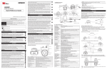
PRO35Digital Image Converter
User Manual
Model 2002
0
Congratulations!
You now have the tools to produce the look and feel of 35mm film using an electronic
camera. The P+S Technik PRO35Digital image converter is designed for use on every 2/3”
video camera with B4 Mount.
The unit is optimized for 35mm lenses with large rear optical elements, such as Cooke S4
Primes, Zeiss Ultra Primes and Zeiss HS and others.
1
Contents
Introduction ................................................................................................................ 3
Attaching the PRO35Digital to Your Camera with Lightweight Support..................... 5
Power Connection...................................................................................................... 6
Back Focus Adjustment ............................................................................................. 7
Back Focus Adjustment Without a Reliable Test Chart ............................................. 8
Worldwide Dealer List ................................................................................................ 9
2
Introduction
Delivery Content PRO35Digital
1 – PRO35Digital image converter with an
Arri PL lens mount and B4 camera mount.
1 – Lightweight support with 15mm Rods;
short and long and a short post.
2 – Protective caps
1 – Power cable
Attaching the PRO35Digital to Your Camera
Avoid Murphy’s Law: Assemble and test the PRO35Digital adapter BEFORE the first day of your
production. After attaching the unit to your camera according to the steps outlined below, be sure to
check each of your lenses, f-stop combinations and shutter adjustments for compatibility.
Items needed before you begin:
(1) 2.5mm hex wrench, like the Xcelite 99-74mm
(2) 35mm format film lens for testing
(3) High quality test chart, such as the Putora HDTV Sharpness Indicator chart; or for fieldwork, the
Putora 7A9 chart
(4) Monitor
Munich / New York, 4 December 2002
P+S Technik GmbH
Rosenheimerstrasse 139
81761 München
Germany
Tel: 49 89 4509 8230
www.pstechnik.de
Technical support: [email protected]
3
Pos. Description
1
INPUT
Comment
7 Pin Fischer female
socket
–Draufsicht Stecker–
2
REMOTE
3 Pin Fisher female
socket
–Draufsicht Stecker–
3
RET
RET button
4
Image
Plane
Line and Tape Hook
5
Control
LED
6
GREEN Æ
RED (low power)
Æ
Blinking light Æ
Wheel
Speed
Control
Manual
GREEN button
RUN
ND
Function
Back
Lever
Focus
Bottom
3/8-inch
thread for
Leightwei
ght
support
Thread
for
Bridgeplat
e support
7
8
9
10
11
Pin 1 – not connected
Pin 2 – VTR trigger
Pin 3 – Bat Pin 4 – not connected
Pin 5 – not connected
Pin 6 – Bat +
Pin 7 – RET
Pin 1 – GND
Pin 2 – N.C.
Pin 3 – VTR
Good speed control
Acceptable speed
Below minimum
speed
Adjustable “ND
Filter”
4
Follow the Steps Below to Properly Attach the PRO35Digital Image Converter to
your Camera with Lightweight Support.
Steps
Instructions
Explanatory Notes
1
Make sure that the quick-lock plate holder on
the bottom of the camera is provided for
lightweight support.
2
Assemble the support bridge delivered with
the PRO35Digital on the quick-lock plate, as
shown in photo.
3
3.1
Assemble the PRO35Digital.
Attach the post to the bottom of the
PRO35Digital unit.
3.2
Lower the support for easier installation
(lever shown as Screw A in photo).
3.3
Loosen two screws on either side of Screw B
in photo.
3.4
Install the PRO35Digital image converter on
the camera (B4 Mount ) and lock the mount.
3.5
Raise the support to the correct height (lever
shown as Screw A in photo).
3.6
Engage and tighten the knob B in the bottom
of the post.
3.7
Tighten the two screws placed either side of
Screw B.
5
Power Connection for the PRO35Digital
To power the PRO35Digital, you need the power cable #19339 included with the unit.
The power cable is fitted with the standard Hirose 12-pin connector for the lens socket on the camera and
the 7-pin Fischer plug for the “Input” socket on the PRO35Digital image converter.
With this power cable, the VTR button on the video camera automatically starts the PRO35Digital unit. Control
the PRO35Digital manually with the RUN button, or by remote control via the Fisher 3-pin “Remote” socket.
Manual “RUN” control and VTR signal logic:
MANUAL “RUN” STATUS
OFF
ON
VTR SIGNAL
RESULT
VTR ON*
Image converter ON
VTR OFF
Image converter OFF
VTR ON*
Image converter ON
VTR OFF
Image converter ON
*During VTR = ON: The camera is in RECORD MODE and the Manual RUN Button on the PRO35Digital
unit is not active.
Other power cables are available from P+S Technik – these cables only allow the manual function of the RUN
button.
6
Back Focus Adjustment
The PRO35Digital image converter has a back focus adjustment that allows the user to match the flange focal
distance of each individual video camera. This adjustment may have to be checked during production if the
camera is subjected to significant temperature fluctuations.
The following describes the simple steps needed to adjust the image converter to the camera:
No special tools are needed.
Steps
Instructions
1
Mount a film lens needs to the adaptor.
2
Place a focusing chart at a reasonable
Explanatory Notes
Select a mid range film lens; around 50mm.
distance and set the focus of the film lens at
that distance.
2.1
Turn the image converter ON.
Open the adjustable ND FILTER to Position 0.
2.2
Close the iris of the film lens to around T4.
2.3
Unscrew the lever, marked “8” in the photo.
Use a good quality monitor to evaluate the
picture.
Turn the ring to adjust for best sharpness.
2.4
Tighten lever 8.
The Pro35Digital image converter is precisely
adjusted for the camera.
7
In the Field, if a Reliable Test Chart is Not Available, Adjust the Back Focus
Using the Following Method:
Steps
Instructions
Explanatory Notes
1
Mount a film lens to the PRO35Digital.
Select a mid range film lens (around 50mm)
2
Use a white chart.
Set a white chart at a reasonable distance to fill the image.
2.1
Turn the PRO35Digital unit OFF.
Open the adjustable “ND filter” to Position 0.
2.2
Close the iris of the film lens far enough to
allow the video camera to show the grain
pattern of the ground glass.
2.3
Unscrew lever “8” (shown labeled in photo),
and turn the ring to adjust the sharpness.
Tighten lever “8.”
2.4
When the grain pattern is sharp, the
Pro35Digital is precisely adjusted for the
camera.
Optional Accessories for the PRO35Digital
•
Putora Sharpness Indicator Chart
•
Extra Power Cable
Optional Lens Mounts
Panavision mount (on request).
Contact your local P+S Technik dealer for prices and availability. See dealer list on next page:
8
Worldwide Dealers
USA/ Canada
ZGC, Inc.
Email: [email protected]
Australia
LEMAC Film & Video Equipment
Email: [email protected]
China
Jebsen & Co. Ltd.
Email : [email protected]
Congo
Films Americas
Carrera. 53 A No. 81-67
Email: [email protected]
England
OpTex Television & Film Equipment
Email: [email protected]
France
EMIT Modern Images Techniques
Email: [email protected]
Holland
Holland Equipment B.V.
Email: [email protected]
Japan
SHOTOKU CORP.
Email : [email protected]
Korea
SAMA Electronics Corp.
Email: [email protected]
Peru, Equador, Bolivia
Moviecenter
Tel: 00511-221 40 58
Singapore
The Film Equipment Gallery Pte. Ltd.
Email: [email protected]
Sweden
Svensk Film & Ljusteknik AB
Email: [email protected]
Taiwan
VIEW POINT IMAGE ASSEMBLINGS
Email : [email protected]
9