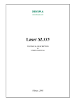
1
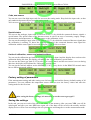
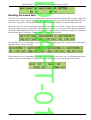
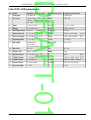
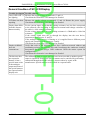
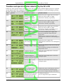
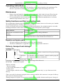
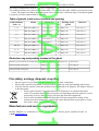
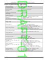
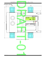
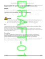
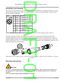
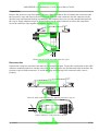
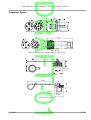
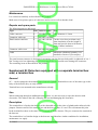
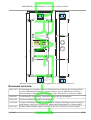
DRAFT-01 ZAM-SERVIS s.r.o. Křišťanova 1116/14 Ostrava-Přívoz 702 00 User Manual Display for Gas Detector SC-LCD No: 207 26 This user manual includes: Instructions for assembly, installation, putting into operation, use, operation, setting, maintenance and service, disassembly and disposal, and specifications Keep this manual for future reference! 15.5.2015 User Manual SC-CH4-TM 1/25 DRAFT-01 ZAM-SERVIS s.r.o. Křišťanova 1116/14 Ostrava-Přívoz 702 00 Content User manual:..................................................................................................................................................3 Warning!....................................................................................................................................................3 Use.................................................................................................................................................................3 Description and operation..............................................................................................................................3 Warning!.........................................................................................................................................................4 Warning! Special conditions of use...............................................................................................................4 Installation and assembly...............................................................................................................................5 Examples of connection.................................................................................................................................6 Operation and setting of SC-LCD..................................................................................................................8 Access to the setting mode........................................................................................................................8 Setting of SC-LCD measurement..............................................................................................................9 Temperature compensation...................................................................................................................9 Analogue input.....................................................................................................................................9 Signalization LED................................................................................................................................9 Other setting of SC-LCD...........................................................................................................................9 Backlight...............................................................................................................................................9 Code, new sensor................................................................................................................................10 Special status......................................................................................................................................10 Limits of calibration, sensor and network address.............................................................................10 Factory setting of parameters..................................................................................................................10 Saving the settings...................................................................................................................................10 Reading the saved data.................................................................................................................................11 List of SC-LCD parameters.........................................................................................................................12 General troubles of SC-LCD Display..........................................................................................................13 Troubles and special statutes detected by the SC-LCD...............................................................................14 Operating instructions..................................................................................................................................15 Maintenance.................................................................................................................................................15 Safety functions and their verification tests.................................................................................................15 Repairs and spare parts................................................................................................................................15 Delivery, transport and storage....................................................................................................................15 Table of glands, cable cross-sections and packing..................................................................................16 Reduction ring and packing instead of the gland....................................................................................16 Fire safety, ecology, disposal, recycling......................................................................................................16 Manufacturer and service organization........................................................................................................16 Related standards, regulations and documents............................................................................................17 Technical parameters and appearance..........................................................................................................18 Dimension drawing............................................................................................................................19 Supplement A: To sensors equipped with M12 connectors.........................................................................20 General....................................................................................................................................................20 Warning!.............................................................................................................................................20 Use...........................................................................................................................................................20 Description..............................................................................................................................................20 Installation and assembly........................................................................................................................21 Operating instructions.............................................................................................................................21 Warning!.............................................................................................................................................21 Connection..........................................................................................................................................22 Disconnection.....................................................................................................................................22 Connector figures....................................................................................................................................23 Maintenance............................................................................................................................................24 Repairs and spare parts............................................................................................................................24 Supplement B: Detectors equipped with a separate terminal box area, a terminal box...............................24 General....................................................................................................................................................24 15.5.2015 User Manual SC-CH4-TM 2/25 DRAFT-01 ZAM-SERVIS s.r.o. Křišťanova 1116/14 Ostrava-Přívoz 702 00 Use...........................................................................................................................................................24 Description..............................................................................................................................................24 Document revisions.....................................................................................................................................25 User manual: This manual includes instructions for assembly, installation, putting into operation, use, utilization, operation, setting, maintenance and service, disassembly and disposal, and specifications. All workers performing installation, putting into operation, operation, maintenance and service must be provably familiarized with this manual. Keep this manual for future reference Warning! • This manual applies to the product put into market after 1 January 2015. Changes in labelling, ordering, control etc. have been made. Ask for respective version of the user manual for older product versions. Use • • The SC-LCD display is designed for displaying volume concentrations of combustible gases of CH4, C2H6, C3H8, C4H10, C5H12, C6H14, C2H2, CO, H2, NH3 in the air from a connected detector ranging from 0 to 5% vol. or 0 to 100% LEL. The explosion-proof version (I M1 Ex ia I Ma, II 1G Ex ia IIC T4 Ga, II 1D Ex ia IIIC T87°C Da) can be used in explosion-risk areas in coal mines or in zones 1, 2, 21 and 22. The additional SC-LCD display is used in cases when the detector is installed in an inaccessible place (e.g. on a ceiling), i.e. out of reach of the operator. SC-LCD is designed so that all signals from the detector go through the display to a connected device. Description and operation • • • • • • • • The device is placed in a polyester box with antistatic finishing. It includes two cable glands, mounting trays, display, setting buttons and LEDs. It enables turning the backlight of the display. All signals from the detector go through the display to a connected device (power supply unit) that supplies the display and in parallel also the detector. The display uses the analogue output of the detector, enables communication but it does not use the digital output of the detector. The analogue output is intended for measuring. It must be set in the same way as the analogue output of the detector (voltage or current output with the adjustable range from 0 to 5.0V or 22.0mA). The measured concentration is displayed. The analogue signal serves also for transferring information about the special status, running calibration and overrange. The display software checks the external power supply (8-30V), internal power supply (3-3.3V) and the device for temperature and checks the memories internally (FLASH, RAM and FRAM). The software calculates and checks the sensor for age and calibration (when the display is ON), saves the values into the internal memory (every minute cyclically for 24 hours) etc. All settings, calibration, readout of current quantities and values from the memory are operated with two buttons on the box side. Legends on the display can be in Czech, Russian or English. The setting mode is accessed after four-digit code is entered. The RS485-IS communication (protocol MODBUS ASCII or RTU) enables readout of current values of concentration, internal temperature, internal and external voltage, operating state of the display or history of these data from the internal memory (they are saved every minute cyclically for 24 hours). The detector with the display device can be connected to the DKD and PNS systems or other systems using a current, voltage, frequency signal or using the MODBUS ASCII or RTU protocol. Up to 5 SC-LCD displays can be theoretically interconnected in series, which is practically limited 15.5.2015 User Manual SC-CH4-TM 3/25 DRAFT-01 ZAM-SERVIS s.r.o. Křišťanova 1116/14 Ostrava-Přívoz 702 00 by the low power of the intrinsically safe power supply unit. Warning! • • • • The leakage current in the cable in case of the current analogue input or the voltage drop in case of the voltage analogue input can result in an error of measurement. The warning “Alarm” LED is not of a latch type. The self-holding alarm function (up to 100% of LEL or range) must be implemented in a connected device. A qualified person must carry out the installation, assembly and setting. The specific application, use or linkage to other devices might develop further requirements for operation, checks and maintenance of SC-LCD. These may be implied by relevant standards and technical recommendations concerning an application, operating assembly or a functional group as created. Introduction of such additional requirements to the application user is the responsibility of supplier of such application, operating assembly or a functional group. Warning! Special conditions of use • • • • • • • • The equipment is designed for low mechanical load conditions. Special attention shall be paid to the location of the equipment and/or it should be additionally protected against mechanical damage. The equipment must be protected from direct UV radiation. When used in the IIC group, the installation and maintenance must eliminate the possibility of danger from electrostatic discharge. This especially applies to inspection glasses and glands. The action of oils, greases, hydraulic liquids and similar chemical agents on the equipment must be minimized. Group III, D, dusts. ◦ The version with mechanical push-buttons must not be used. The version controlled by a magnet must be used. ◦ A version using connectors cannot be used. The enclosure of the equipment consists of a box, a head, a display eye-slit cover, a display eye-slit and an eye-slit for LED, a gland or a connector. The version with a separate connecting area also has a box of the area. It is only allowed to open the lids of the boxes, release the bushing for inserting the cable and connect the cable to the connector. It is prohibited to dismount the other components forming the enclosure and to dismount the top PCB with the display. If metal parts are fixed to the equipment, they are sealed with a permanent seal; the seal can only be renewed by the manufacturer or an authorized service. Do not expose the equipment to extremely strong sources of magnetic fields. Push-buttons can be self-actuated or the equipment may malfunction. 15.5.2015 User Manual SC-CH4-TM 4/25 DRAFT-01 ZAM-SERVIS s.r.o. Křišťanova 1116/14 Ostrava-Přívoz 702 00 Installation and assembly 1. Select the place to install the display to minimize shocks, mechanical stresses, interfering electromagnetic fields, temperature and moisture conditions. Check the box, cable glands and packings for good condition before using. Attach SC-LCD onto a solid base through mounting trays with 4 Ø4mm screws or directly through the holes in the box. 2. The display must be installed in explosion-risk areas in accordance with this user manual, local operating instructions, EN 50303, EN 50394-1, EN 60079-0, EN 60079-11, EN 60079-25, EN 61241-0, EN 61241-11 and other valid regulations and standards. 3. Connect the analogue output of the detector to the screwless terminals 1 and 2. Connect the analogue input of the connected device to terminals 11 and 12. Connect the supply voltage 8-30V from the approved intrinsically safe power supply unit to terminals 13 and 14. The terminals 3 and 4 enable parallel power supply of the detector from the same power supply unit. The transistor output of the detector from terminals 5 and 6 is to terminals 15 and 16. The communication conductors A and B shall be connected to terminals 7, 8, 17 and 18. The bus can be ended with two jumpers to H51. The max. cross-section of connecting wires is 2.5mm2 for a wire and 1.5mm2 for a segmental conductor, the wire stripping length is 5-6 mm. The conductor ends must not be free-standing. When handling, pay close attention, do not damage the electronics. 4. The cable diameter in the M20 gland can be 6-12mm; glands given in the table in the paragraph for orders can be ordered for a different cable cross-section. It is used only for a firm-installed cable. Tighten the gland properly, it must grip and seal the cable sufficiently. Reduce the tensile and torsional stress of the cable in place of the gland during installation. After the installation put the box cover on and seal properly. 5. Set the required parameters of the display according of the following chapter. Terminal block and setting jumpers of SC-LCD 15.5.2015 User Manual SC-CH4-TM 5/25 DRAFT-01 ZAM-SERVIS s.r.o. Křišťanova 1116/14 Ostrava-Přívoz 702 00 Examples of connection Stab. CPU, LCD 1k H51 220 U,I Analog out Power Digital out RS485-IS 11+ H51 75 75 RS485 driver 1k 50 1+ 100k 12- 2- 13+ 3+ 14- 4- 15+ 5+ 16- 6- 17A 7A 18B 8B Input-output circuits of SC-LCD Analog in Power Digital in RS485-IS Example of wiring including the mine data concentrator DKD2000, detector SC-CH4 and SC-LCD. The frequency output of SC-CH4 is set at 200-600Hz and synchropulse at 200us. The jumper wire H52-PNP connects the harness 3 and 5 internally. The current output for SC-LCD has the range of 0.2-1mA or 1-5mA and the harnesses 11 and 12 are connected inside SC-LCD. The assembly can be connected only to 80mA inputs 1 and 3. Max. resistance of the supply line loop of DKD2000 from the surface feeder is 450Ω for 1 detector and 300Ω for 2 detectors . 15.5.2015 User Manual SC-CH4-TM 6/25 DRAFT-01 ZAM-SERVIS s.r.o. Křišťanova 1116/14 Ostrava-Přívoz 702 00 Example of wiring including the box PNS 04/M, detector SC-CH4 and SC-LCD. The current output of SC-CH4 is set at 0.2-1mA. Max. resistance of the supply line loop of PNS from the surface feeder is 800Ω. Example of wiring including an isolating switching amplifier, intrinsically safe power supply unit, detector SCCH4 and SC-LCD. SC-CH4 has set a frequency output. The NAMUR output is realised by a jumper wire H52-10k. The range of the current output for SC-LCD is 0.2-1mA or 1-5mA and the harnesses 11 and 12 are connected inside SC-LCD. Example of wiring with disconnecting switching amplifier, an intrinsically-safe source and an additional display. SC-CH4 has a frequency output set. The H52-10k jumper ensures the output of NAMUR type. The current output for SC-LCD has the range of 0.2-1mA or 1-5mA and bundles 11 and 12 are joined inside the SC-LCD. 15.5.2015 User Manual SC-CH4-TM 7/25 DRAFT-01 ZAM-SERVIS s.r.o. Křišťanova 1116/14 Ostrava-Přívoz 702 00 Operation and setting of SC-LCD zam servis ON ALARM Křišťanova 1116 / 14 70200 Ostrava zam servis 1026 Place where to approximate the magnet to control the “Upper Button” Version without mech. buttons Upper Button Calibr. >Access to the calibration and setting mode OK>Browsing over the set figures OK> Confirmation of the set or selected value +>Increase of data history by minutes Lower Button Browse> Access to the mode for reading the saved data Browse>Browsing over individual saved quantities +>Increasing the set figure or selection of a value Place where to approximate the magnet to control the “Lower Button” Version without mech. buttons All settings, calibration, readout of current quantities and values from the memory are operated using two buttons on the box side. To preserve sufficient IP protection, the push-buttons are replaced with reed contacts. These contacts are controlled by means of approximating the magnet held in hand and they functionally substitute push-buttons. A suitable place for approximating the magnet is situated on the right side near screws on the lid; the exact place and distance needs to be tested. A version with mechanical push-buttons can only be produced on the basis of a special order. The version with mechanical pushbuttons cannot be used for group III – dusts; it can only be used for groups I and II! During the setting the SC_LCD operation is not limited in any way and it is fully functional according to the original setting. Thanks to this, parameters can only be checked without influencing the function of the display. If push-buttons are not used for more than 4 minutes, the detector starts the selected mode and changes over to the display of the basic screen. When a parameter (calibration, the setup of switching values etc.) is changed by means of the RS485 interface, the check of correctness must be performed by the readout of the set parameters on the equipment or by back uploading from the equipment and manual verification of the received values with the set ones. Access to the setting mode When the screen is in the measurement mode, enter the setting mode by pressing the upper button nast». The first selection is the language screen. Use the lower button +» to select Czech, Russian or English. Confirm the selection using the upper button OK». Then enter the four-digit access code. Change the figures using the lower button +». Using the upper button OK» go through the figures and confirm the resulting code. When the code has not been changed, the default value set by the manufacturer is 0000. If the correct code is not entered, the screen will return to the measurement mode. If you forget your access code, it is possible to restore it by default setting in the service centre only. 15.5.2015 User Manual SC-CH4-TM 8/25 DRAFT-01 ZAM-SERVIS s.r.o. Křišťanova 1116/14 Ostrava-Přívoz 702 00 Setting of SC-LCD measurement Temperature compensation You can set parameters of measurement by entering YES or you can leave them out by NO. To select YES or NO use the lower button +»; to confirm the selection use the upper button OK». When production values were saved in the previous setting mode or the display is being programmed for the first time, you can calibrate (specify) the internal temperature sensor. Carry out this specification when the device is cold and turned on only shortly because the internal temperature is a slightly higher during operation. Set the box temperature measured with a precise thermometer (±1ºC). Now it is possible to select which gas will be measured by the display and shown on the display and whether the units of % vol. (% of gas volume in the air) or % LEL (% of the gas lower explosion limit) are used. The range of measurement for the analogue input can also be adjusted. Analogue input Select the current or voltage analogue input. Then set the min. value that will correspond to 0% vol. and the max. value that will correspond to the measuring range. The minimum and the maximum can be set in the range of 0-22.0mA or 0-5.0V. The standard range of 4 - 20mA can be energy-consuming therefore the ranges of 0.2-1mA, 1-5mA or 0.4-2V are used. The selected range must correspond to the range of the connected detector. Signalization LED You can set a limit concentration to light up the red “ALARM” LED in the range from 0 to 15% vol. The signalization up to 100% LEL or range is not of a latch type, and therefore after the danger passes off, the LED will go out. Other setting of SC-LCD Backlight Now you can set other (additional) parameters by entering YES or you can leave them out by entering NO. At first you can set the display backlight mode. The display can always be turned on, turned off or turned on only for 5 sec after the button is pressed. The turned off backlight saves 13mA of the consumption. You can also set the double-high type size of the screen in the measurement mode. 15.5.2015 User Manual SC-CH4-TM 9/25 DRAFT-01 ZAM-SERVIS s.r.o. Křišťanova 1116/14 Ostrava-Přívoz 702 00 Code, new sensor You can set a new four-digit input code for access to the setting mode. Keep back the input code, so that only authorized persons can access to the setting mode. You can set a new sensor after it is replaced in the detector. This setting resets the sensor age counter. Special status You can set the analogue input value (0-24.2mA or 0-5.5V) by which the connected detector signals a special status. The special status of the detector occurs in case of an error of a memory, supply voltage, measurement, and temperature, or when the sensor or the calibration is old. You can set the analogue input value (0-24.2mA or 0-5.5V) by which the connected detector signals that the calibration is running. To detect the running calibration, the connected detector must signal the calibration with the same signal or reversed analogue output for 60 sec at least. Limits of calibration, sensor and network address You can set the calibration age limit (0-255 days). If it is more than 0 and the display does not detect the calibration during this time, the display will indicate the “Old calibration” special status. You can set the sensor age limit (0-255 weeks). If it is more than 0 and the new sensor is not set during this time, the display will indicate the “Old sensor” special status. You can set the network address on the MODBUS (1-247). Every device in the RS485-IS network must have a different network address. Factory setting of parameters If the measurement setting and other setting were left out, you can load the factory (default) setting of all parameters. You can calibrate the temperature sensor after you save the factory values and enter the setting mode for the first time. After saving the factory settings, it is necessary to set the correct gas type!!! Saving the settings In the end, you can save each of the above set values in the memory. After you enter YES, you will be asked again and after you enter YES once again, all of the data will be saved in the memory and the display device will be reset according to the new parameters and changed over to the measurement mode 15.5.2015 User Manual SC-CH4-TM 10/25 DRAFT-01 ZAM-SERVIS s.r.o. Křišťanova 1116/14 Ostrava-Přívoz 702 00 Reading the saved data SC-LCD saves measured values of concentration, internal temperature, internal and external voltage and operating status every minute cyclically for 24 hours. You can read the data through RS485-IS (the protocol is compatible with MODBUS ASCII or RTU) or on the display if you do not know the code. When the screen is in the measurement mode, you can change over to the reading mode to read saved data by pressing the lower button list». With the upper button +», you can move the data history minute by minute. With holding the button +», the time moves more quickly. If the power supply was restarted, then the time data is not unique, which is indicated by the question mark. By pressing the lower button list», you can select the individual quantities (concentration, temperature, internal voltage, external voltage). By pressing the lower button list» once again, you can display the current age of calibration and sensor. After you press the button list» once again, the screen will change over to the measurement mode. 15.5.2015 User Manual SC-CH4-TM 11/25 DRAFT-01 ZAM-SERVIS s.r.o. Křišťanova 1116/14 Ostrava-Přívoz 702 00 List of SC-LCD parameters No. Name Possible range of values Production value Common used values 1 Language CZ,RU,EN CZ CZ,RU,EN 5 Gas type CH4, C2H6, C3H8, C4H10, CH4 C5H12, C6H14, C2H2, CO, H2, NH3 CH4, H2 6 Units % vol. % LEL % vol. % vol. % LEL 7 Range 0...15.00% vol. 5.00% 5.00%, 4.00% 8 Analogue Input Current Voltage Current Current 9 MinAnalogVal 0...22.0mA 0...5.0V 0.2mA 0.2mA 1mA 4mA 0.4V 10 MaxAnalogVal 0...22.0mA 0...5.0V 1mA 1mA 5mA 20mA 2V 11 SignalingLED 0...15.00% 1.0% 0...1.50% 13 Backlight Always ON Never ON Never ON 5sec after button is pressed Never ON 14 Big LCD No, Yes No No, Yes 16 Input Code 0000...9999 0000 xxxx 18 Special Status 0...24.2mA 0....5.5V 0 0mA 0V 19 Calibr. Status 0...24.2mA 0...5.5V 0 0.1mA 0.5mA 2mA 0.2V 20 Calibr. Limit 0...255 days 0 days 10days 20days 40days 21 Sensor Limit 0...255 weeks 0 weeks 100, 150, 200 weeks 22 NetworkAddr. 1...247 2 1-247 15.5.2015 User Manual SC-CH4-TM 12/25 DRAFT-01 ZAM-SERVIS s.r.o. Křišťanova 1116/14 Ostrava-Přívoz 702 00 General troubles of SC-LCD Display Trouble description Possible solution Green LED “ON” is Measure the supply voltage on terminals 13 and 14. not lighting Check that the electronics is not damaged or flooded. LCD does not show anything Measure the supply voltage on terminals 13 and 14. Restart the power supply. Check that the electronics is not damaged or flooded. Display data differs from the detector data noticeably For the current input, check that the sensing resistance incl. the line corresponds to the allowed value according to the detector manual and leakage resistance of the cable is >100x sensing resistance. For the voltage input, check that the loading resistance is <50kΩ and is >100x line resistance. If the current signal does not go through the display into the next device, interconnect the harnesses 11 and 12. If the analogue signal source is floating or it is supplied from a different power supply unit, interconnect the harnesses 2 and 4. Check that the electronics is not damaged or flooded. Display in RS485 does not communicate Verify that each of the network devices has a different network address and terminating resistors are set at the bus ends. Interchange the conductor A and B. Interconnect the device using a GND conductor. Check the master system for configuration. Check that the electronics is not damaged or flooded. The detector does not respond to buttons; it has a special status value at the analogue output and some of the special statuses are reported on the display unit. The calibration limit or sensor age limit have been exceeded or another special status is signalized. Some of the special statuses can be cancelled by performing calibration through the RS485 interface whereas others by repair at the manufacturer. Special statuses are described in a separate table. 15.5.2015 User Manual SC-CH4-TM 13/25 DRAFT-01 ZAM-SERVIS s.r.o. Křišťanova 1116/14 Ostrava-Přívoz 702 00 Troubles and special statutes detected by the SC-LCD If there are more special statuses at the same time, the special status with the highest priority is reported on the display and in the communication protocol. Statuses in the table are sorted according to priority; the first is the status with the highest priority. State 47-0 47-1 47-2 44 45 38 46 36 37 40 39 15.5.2015 Screen Trouble description Possible solution Critical error of program memory. Displayed concentration may be wrong. Restart the power supply unit. Check that there is no device with very high interference intensity in proximity. Critical error of data memory. Displayed concentration may be wrong. Restart the power supply unit. Check that there is no device with very high interference intensity in proximity. Setting memory could not repair by itself. Displayed concentration may be wrong. Restart the power supply unit. Check that there is no device with very high interference intensity in proximity. Try to save the new values in the memory. External supply voltage is out of range 8 - 30V. Displayed concentration may be wrong. Use a more suitable power supply unit. Decrease the distance from the power supply unit. Increase cross-sections of supply wires. Check that the electronics is not damaged or flooded. Internal supply voltage is out of range 3.0 – 3.3V. Restart the power supply unit. Check that the electronics is not damaged or flooded. Internal temperature is out of range -40°C...- +60°C. Increase the distance of the device from the heat sources. Save production settings and calibrate the temperature sensor. Connected detector indicates a special status with the analogue output. Check the connected detector. Check the analogue output. Connected detector Check the connected detector. Check the indicates running calibration analogue output. with the analogue output. Analog value from the detector is out of measurement range. Detector can indicate concentration more than 5%CH4. Check the connected detector. Check the analogue output. Sensor lifetime in the detector will expire. Replace the sensor in the detector and set a new one in the detector and the display. Or set also a longer limit age of the sensor. Old calibration of detector. Displayed concentration may be with error. Calibrate the detector. Or set a longer limit age of calibration. User Manual SC-CH4-TM 14/25 DRAFT-01 ZAM-SERVIS s.r.o. Křišťanova 1116/14 Ostrava-Přívoz 702 00 Operating instructions • The measurement is unattended. The attendance of the system depends on the application. The detector is operated according to its user manual, see the control and setting of SC-LCD. Maintenance • • Remove dust and impurities from the surface using a dry cloth, brush or broom. Then clean the surface with a cloth wetted with water with common detergents or cleaners based on alcohol. It is recommended to have the unit checked by personnel from the manufacturer or a relevant authorised representative once a year. Safety functions and their verification tests We recommend performing tests of the functions used at calibration, however at least once per 6 months. The minimum frequency of safety signal recovery is 0.4 sec. Unless verification tests were performed after finishing maintenance, the equipment must be reset after finishing maintenance which can be performed by a short interruption of power supply. Safety function Verification test Showing the concentration on the display Check the displayed values during calibration. Red LED During calibration test with a gas with the concentration at least by 10% higher than the set value whether the LED turns on. Repairs and spare parts • • All repairs and spare parts shall be provided by the manufacturer. The data in Addendum A is applicable to detectors equipped with connectors. Delivery, transport and storage Ordering code: SC-LCDx x Push-buttons B – mechanical push-buttons, cannot be used for group III, dusts. For special order only. Connection type G - gland, K – M12 x 8 connector - cannot be used for group III, T – separate terminal area, terminal box Detector type SC-LCD Unless the version is specified in the order, the following will be delivered: SC-LCD-G Display with a gland. •Delivery includes: user manual ◦Copies of the Declaration of Conformity ◦Product itself ◦Control magnet, with the version without mechanical push-buttons only, 1 pc per 4 detectors in the delivery ◦This •There is no cable for detectors equipped with a connector and the cable connector is not part of delivery and it must be ordered separately. •During transport of all parts it is necessary to minimise any possible vibrations and impacts. Storage in 15.5.2015 User Manual SC-CH4-TM 15/25 DRAFT-01 ZAM-SERVIS s.r.o. Křišťanova 1116/14 Ostrava-Přívoz 702 00 dry rooms at temperatures from 0 °C to 40 °C in one layer only. •As standard, the detector is delivered with the M20 x 1.5 gland for the cable with the cross-section of 6.5 – 12 mm. The gland according to the table below can be selected for a different range. If a different gland is required, its order number must be specified. Table of glands, cable cross-sections and packing Cable diameter from - to Gland Order no. cl. no. Packing to the gland Order no. 5 - 10 HSK-K-Ex M16 x 1,5 1.295.1602.50 22 HSK-V-Ex 1.296.1101.11 3-7 HSK-K-Ex M16 x 1,5 1.295.1602.51 22 HSK-V-Ex 1.296.0701.11 4-8 HSK-K-Ex M16 x 1,5 1.291.1602.50 19 HSK-V-Ex 1.296.0901.11 3-6 HSK-K-Ex M16 x 1,5 1.291.1602.51 19 HSK-V-Ex 1.296.0701.11 5-9 HSK-K-Ex M20 x 1,5 1.291.2002.51 24 HSK-V-Ex 1.296.0901.11 6.5 - 12 HSK-K-Ex M20 x 1,5 1.291.2002.50 24 HSK-V-Ex 1.296.1301.11 10 - 14 HSK-K-Ex M20 x 1,5 1.295.2002.50 27 HSK-V-Ex 1.296.1301.11 7 - 12 HSK-K-Ex M20 x 1,5 1.295.2002.51 27 HSK-V-Ex 1.296.1301.11 Reduction ring and packing instead of the gland Reduction ring for M16 from the M20 hole M20x1.5 / M16x1.5 Packing instead of the gland M20x1.5 V-Ex 1.297.2001.50 M16x1.5 V-Ex 1.297.1601.50 Packing instead of the gland RSD-INOX-Ex 1.098.2016.50 Fire safety, ecology, disposal, recycling • • • Do not expose to open flame, harmful substances result from combustion. When used correctly in operation, it does not affect negatively to the surrounding and ecology. After the lifetime expires, return the product to the manufacturer for disposal. The address is given in this document. • Electric and electronic equipment must not be disposed of as common municipal refuse. The product must be delivered to the corresponding collection point for correct processing, recovery and recycling of electric and electronic equipment. • Ask for more detailed information about the collection point and recycling of this product from local authorities, a municipal refuse disposal firm in your place or from your dealer where you bought the product. Manufacturer and service organization ●ZAM - SERVIS s.r.o. Křišťanova 1116/14, 702 00 Ostrava - Přívoz, phone: (00420) 556 685 111 e-mail: [email protected] 15.5.2015 User Manual SC-CH4-TM 16/25 DRAFT-01 ZAM-SERVIS s.r.o. Křišťanova 1116/14 Ostrava-Přívoz 702 00 Related standards, regulations and documents LVD: CSN 33 2000–4–41 Electrical installations of Buildings - Part 4: Protection for safety - Chapter 41: Protection against electric shoc EN 60529 Degrees of protection provided by enclosures (IP Code) EMC: EN 61000-6-2 Electromagnetic compatibility (EMC) - Part 6-2: Generic standards - Immunity for industrial environments EN 61000-6-3 Electromagnetic compatibility (EMC) - Part 6-3: Generic standards - Emission standard for residential, commercial and light-industrial environments EN 50270 Electromagnetic compatibility - Electrical apparatus for the detection and measurement of combustible gases, toxic gases or oxygen ATEX: EN 50303 Group I, Category M1 equipment intended to remain functional in atmospheres endangered by firedamp and/or coal dust EN 60079-0 Electrical apparatus for explosive gas atmospheres - Part 0: General requirements EN 60079-11 Explosive atmospheres - Part 11: Equipment protection by intrinsic safety "i" EN 60079-25 Electrical apparatus for explosive gas atmospheres - Part 25: Intrinsically safe systems EN 60079-29-1 Explosive atmospheres - Part 29-1: Gas detectors - Performance requirements of detectors for flammable gases EN 60079-29-2 Explosive atmospheres - Part 29-2: Gas detectors - Selection, installation, use and maintenance of detectors for flammable gases and oxygen EN 1127-1 Explosive atmospheres - Explosion prevention and protection - Part 1: Basic concepts and methodology EN 1127-2 Explosive atmospheres - Explosion prevention and protection - Part 2: Basic concepts and methodology for mining Other documents: Communication protocol and Data Map of SC-... sensors 15.5.2015 User Manual SC-CH4-TM 17/25 DRAFT-01 ZAM-SERVIS s.r.o. Křišťanova 1116/14 Ostrava-Přívoz 702 00 Technical parameters and appearance Measurement range Ambient temperature Relative humidity Protection 0 - 5% vol. or 0...100% LEL -20...+50°C max. 95%, no condensation IP65 Dimensions including glands 170x112x63mm Total weight 500g Included electronics 100g Max. cross-section of connecting conductors full wire 2.5mm2, segmental conductor 1.5mm2 wire stripping length 5-6 mm Cable diameter in M20 gland 6.5 - 12mm Supply voltage 8 - 30V (8 - 22V for IIC) Current take-off Voltage analogue input 20mA (+ 13mA when the display is backlit) (+ 5mA when there is RS485 communication) Adjustable from 0.0 to 5.0V (overrange max. 5.5V) Input resistance approx. 100 Inserted into the measuring loop resistance 50 Current analogue output Adjustable from 0.0 to 22.0mA (overrange max. 24.2mA) Inserted into the measuring loop resistance 50 Analog input error <±1% range Explosion protection I M1 Ex ia I Ma II 1G Ex ia IIC T4 Ga II 1D Ex ia IIIC T87°C Da Input parameters: Terminals 11/1-12/2; 13/3-14/4; 15/516/6;17/7-18/8 Ui=30V (I,IIA,IIB,III); Ui=22V (IIC); Ci=0; Li=10μH Pi=3.22W or 3.3W for Tamb=-20°C to 40°C (I) Pi=1.25W or 1,3W for Tamb=-20°C to 40°C (II, III) Output parameters: Terminals 11/1-12/2; 13/3-14/4; 15/516/6 Uo=30V (I,IIA,IIB,III); Uo=22V (IIC); Co=3μF (I); Co=165nF (I,III) Lo=30mH(I), Lo=4mH (II,III); Po=3.22W or 3.3W for Tamb=-20°C to 40°C (I) Po=1.25W or 1.3W for Tamb=-20°C to 40°C (II, III) Output parameters: Terminals 17/7-18/8 Uo=4.15V; Io=149mA;Po=155mW; Co=100μF; Lo=2mH(I,IIA,IIB,III), Lo=1mH (IIC); Recommended lifetime is 5 years. 15.5.2015 User Manual SC-CH4-TM 18/25 DRAFT-01 ZAM-SERVIS s.r.o. Křišťanova 1116/14 Ostrava-Přívoz 702 00 Dimension drawing Mechanical dimensions of SC-LCD 15.5.2015 User Manual SC-CH4-TM 19/25 DRAFT-01 ZAM-SERVIS s.r.o. Křišťanova 1116/14 Ostrava-Přívoz 702 00 Supplement A: To sensors equipped with M12 connectors. General SC-... sensors may be equipped with connectors instead of cable glands. Connectors are made with 8 pins and all detector terminals are brought out to the connector. Connectors are already mounted on the detector body by the manufacturer. Cable connectors are delivered separately, i.e. a connector, a cable, and a connector cap separately. Assembling is carried out by the user. Warning! With regard to surface distances and clearances in the connector and cable parameters, it is necessary, while connecting, to consider the fact that all inputs and outputs of the detector as well as the circuits in the connected cable are part of one intrinsically safe circuit. The version with connectors cannot be used in the dusty environment, group III. Use Connection using the connector makes it possible to promptly replace one detector with another. When replacing, it is not necessary to open the detector. This makes it possible to calibrate detectors in workshop premises, for example. At the measurement point, you can replace the existing detector with the calibrated one and take the one which was used to the workshop and calibrate it there. Description It is an M12 A-coded industry standard connector, "M12 connectors A-coded"; 8-pin connectors. Instead of the gland on the detector body, there is a zinc/nickel-plated brass male connector with a protective cap that must be screwed in case that the connector with cable is not connected. There is a plastic connector with a metal nut and a protective cap on the cable. The connector cap must be put on or screwed onto the connector if the connector cable is not connected to the connector on the detector body. The connector has screw-type terminals. 15.5.2015 User Manual SC-CH4 20/25 DRAFT-01 ZAM-SERVIS s.r.o. Křišťanova 1116/14 Ostrava-Přívoz 702 00 Installation and assembly The connector on the detector body is delivered installed by manufacturer; including connector cover; pin numbering and wiring colour codes are referred to further. Connector pin numbering is consistent with detector terminal numbering. 8-pin Pin Colour Terminal 2 3 1 4 8 5 6 7 1 white 2 brown 3 green 4 yellow 5 grey 6 pink 7 blue 1 Analogue out + 2 Analogue out 3 Power + 4 Power - 5 Digital out + 6 Digital out 7 RS485A 8 red 8 RS485B Wiring of connectors on detector body; pins are drawn when looking into the connector. The cable connector uses the same wiring colour codes as the connector on the detector body. Wire stripping length and connector assembling is indicated in the figure below. It is absolutely necessary to keep the lengths and after assembling the connector, tighten the connector bushing properly so that it can grip the cable jacket. Use a 2 x 0.5 screwdriver for the screw terminals. After assembling, attach the cover to the cable and secure from losing it. 3 2 8 1 4 5 6 7 Adapting the cable conductor ends, connector assembling; pins are numbered when looking at screw-type terminals, Operating instructions Warning! Connectors and caps may never remain open! Either protective caps are put on the connectors or the connectors are connected and consequently, the caps of connected connectors are connected together! Never use a pair of pliers while handling the connector! 15.5.2015 User Manual SC-CH4 21/25 DRAFT-01 ZAM-SERVIS s.r.o. Křišťanova 1116/14 Ostrava-Přívoz 702 00 Connection ~62 Remove the protective caps from both connectors. Make sure that no dirt is found in the connectors and their protective caps and remove the dirt if present. Slide the cable connector into the connector on the detector body and turn until locking mechanisms and connector keys are correctly matched and push all the way in. Apply adequate torque to the knurled nut on the cable connector to secure the connection. Screw the connector caps together and tighten slightly. . Connection of connectors and protective caps. Disconnection ~22 Separate the connector caps from each other by screwing them apart. Loosen the securing nut on the cable connector manually and screw out the nut as long as the connectors are disconnected from each other. Put protective caps on both connectors. To avoid damaging and dirtying of the connector cable, store it properly. Detector body with the connector and the protective cap on. Cable connector with protective cap on. 15.5.2015 User Manual SC-CH4 22/25 DRAFT-01 3 1 4 1 4 2 3 8 5 7 6 20 2 M20 x 1,5 2 13 M12x1 Connector figures Ø 23 / SW 22 mm ZAM-SERVIS s.r.o. Křišťanova 1116/14 Ostrava-Přívoz 702 00 Panel-mount connector, view to the connector, dimensions. ~54 2 1 2 3 4 3 1 4 8 7 6 5 Ø 20,2 M12x1 2 SW 18 mm 11 60 15,5 1,5 Cable connector, view to the connector, dimensions. M12 x 1 Ø 20 Panel-mount connector cap. 21 ~125 M12 x 1 Ø 20 Cable connector cap. 15.5.2015 User Manual SC-CH4 23/25 DRAFT-01 ZAM-SERVIS s.r.o. Křišťanova 1116/14 Ostrava-Přívoz 702 00 Maintenance It is carried out similarly as described for the product. Make sure to keep inner spaces of connectors and covers as well as threads clean! Repairs and spare parts The following parts are delivered. Type Pins Order number Note Cable connector cable diameter 6–8 mm Connector cable cap Panel-mount connector Connector cable cover Cable 8 99-0486-12-08 8 08-2425-010-000 8 09-3481-642-08 8 08-2989-000-000 LiYY 8 x 0.34 Cut the wires short to 60mm, strip 8mm insulation off at the length of 8mm and provide them with ferrules with 0.34mm2 insulation Minimum withdrawal quantity is in hundreds of metres. Upon enquiry. The panel-mount connector is designed for mounting onto the detector body and it is tightened at 2 to 3 Nm. Owing to its low tightening nut, it is necessary to be very careful not to damage the connector. The remaining items as described for the product. Supplement B: Detectors equipped with a separate terminal box area, a terminal box General SC-... can be equipped with terminal boxes instead of glands. Terminal boxes are of the same type as the body of the detector, they are only smaller. Terminal boxes are mounted at the manufacturer already. Use When connecting through an additional terminal box, it is not necessary to open the detector with electronics. This reduces the risk of dirtying the area and damaging the electronics. Description The terminal box is fixed to the detector with a threaded tube at the place of glands and reinforced with jumpers. Between walls of the terminal box and the detector there is a seal. Never dismount this joint. In the terminal box there is the same set of terminals as in the detector. They are connected to terminals in the detector. The terminal box is of similar design as the detector itself therefore similar conditions for installation, maintenance etc. apply. 15.5.2015 User Manual SC-CH4 24/25 DRAFT-01 ZAM-SERVIS s.r.o. Křišťanova 1116/14 Ostrava-Přívoz 702 00 112 102 63 Vývodka Hummel HSK-K M20x1,5 (kab. 6-12) včetně těsnění zam servis ON ALARM ~330 ~180 Křišťanova 1116 / 14 70200 Ostrava zam servis 1026 4x montážní úchyt Weidmuller 9510900000 (Bopla 21004250, Rose 10.03 11 01) včetně šroubů a podložek Vývodka Hummel HSK-K M20x1,5 (kab. 6-12) včetně těsnění Mechanical dimensions of SC-CH4, equipped with a separate terminal box Document revisions 18/09/ 2012 Reformatting the document, removal of information not related to the existing software version, additional information for current software version. Modification of factory default settings. Calibration limit changed to 0 days. Description of connectors added. 18/04/2013 Formal changes, reformatting. Unification, change the type description. 03/02/2014 Detailed designation for different atmospheres. 11/12/2014 Change in labelling according to new standards, change in labelling in orders, change in push-buttons. New types of connection, glands and packing added. Ii=0.66mA added. 15/05/2015 Invalid standard deleted, small corrections in the text, corrections of texts in figures. 15.5.2015 User Manual SC-CH4 25/25