1
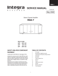
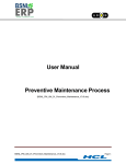
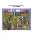
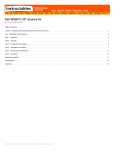
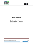
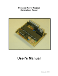
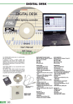
User’s Manual
MUB-K0-K0S LCD Multi-Use Board
for K0 and K0S Microcontrollers
Document no. 50850-1
©1998 NEC Electronics Inc. All rights reserved. Printed in U.S.A.
Date
Version
October 1998
2
Comments
No part of this document may be copied or reproduced in any form or by any means without the prior written
consent of NEC Corporation. NEC Corporation assumes no responsibility for any errors that may appear in this
document. NEC Corporation does not assume any liability for infringement of patents, copyrights, or other
intellectual property rights of third parties by or arising from use of a device described herein or any other liability
arising from use of such a device. No license, either express, implied, or otherwise, is granted under any
patents, copyrights, or other intellectual property rights of NEC Corporation or others. While NEC Corporation
has been making continuous effort to enhance the reliability of its semiconductor devices, the possibility of
defects cannot be eliminated entirely. To minimize risks of damage or injury to persons or property arising from a
defect in an NEC semiconductor device, customers must incorporate sufficient safety measures in its design,
such as redundancy, fire-containment, and anti-failure features. NEC devices are classified into the following
three quality grades: “Standard,” “Special,” and “Specific.” The Specific quality grade applies only to devices
developed based on a customer-designated “quality assurance program” for a specific application. The
recommended applications of a device depend on its quality grade, as indicated below. Customers may check
the quality grade of each device before using it in a particular application. Standard: Computers, office
equipment, communications equipment, test and measurement equipment, audio and visual equipment, home
electronic appliances, machine tools, personal electronic equipment, and industrial robots. Special:
Transportation equipment (automobiles, trains, ships, etc.), traffic control systems, anti-disaster systems, anticrime systems, and safety equipment (not specifically designed for life support). Specific: Aircraft, aerospace
equipment, submersible repeaters, nuclear reactor control systems, and life support systems or medical
equipment for life support, etc. The quality grade of NEC devices is “Standard” unless otherwise specified in
NEC’s data sheets or data books. If customers intend to use NEC devices for applications other than those
specified for Standard quality grade, they should contact an NEC sales representative in advance.
In North America: No part of this document may be copied or reproduced in any form or by any means without
the prior written consent of NEC Electronics Inc. (NECEL). The information in this document is subject to change
without notice. All devices sold by NECEL are covered by the provisions appearing in NECEL Terms and
Conditions of Sales only, including the limitation of liability, warranty, and patent provisions. NECEL makes no
warranty, express, statutory, implied, or by description, regarding information set forth herein or regarding the
freedom of the described devices from patent infringement. NECEL assumes no responsibility for any errors that
may appear in this document. NECEL makes no commitments to update or to keep current information
contained in this document. The devices listed in this document are not suitable for use in applications such as,
but not limited to, aircraft control systems, aerospace equipment, submarine cables, nuclear reactor control
systems, and life support systems. “Standard” quality grade devices are recommended for computers, office
equipment, communication equipment, test and measurement equipment, machine tools, industrial robots,
audio and visual equipment, and other consumer products. For automotive and transportation equipment, traffic
control systems, and anti-disaster and anti-crime systems, it is recommended that the customer contact the
responsible NECEL salesperson to determine the reliability requirements for any such application and any cost
adder. NECEL does not recommend or approve use of any of its products in life support devices or systems or in
any application where failure could result in injury or death. If customers wish to use NECEL devices in
applications not intended by NECEL, customers must contact the responsible NECEL salespeople to determine
NECEL's willingness to support a given application.
Contents
1. Introduction . . . . . . . . . . . . . . . . . . . . . . . . . . . . . . . . . . . . . . . . . . . . . . . . 1-1
1.1 Description . . . . . . . . . . . . . . . . . . . . . . . . . . . . . . . . . . . . . . . . . . . . 1-1
1.2 Features . . . . . . . . . . . . . . . . . . . . . . . . . . . . . . . . . . . . . . . . . . . . . . 1-1
1.3 Starting Up . . . . . . . . . . . . . . . . . . . . . . . . . . . . . . . . . . . . . . . . . . . . 1-2
2. Kit Components . . . . . . . . . . . . . . . . . . . . . . . . . . . . . . . . . . . . . . . . . . . . 2-1
3. Hardware . . . . . . . . . . . . . . . . . . . . . . . . . . . . . . . . . . . . . . . . . . . . . . . . . . 3-1
3.1 Sockets . . . . . . . . . . . . . . . . . . . . . . . . . . . . . . . . . . . . . . . . . . . . . . . 3-1
3.1.1 µPD78P0308 Device and IE-78001 Emulator . . . . . . . . . . 3-1
3.1.2 ND-K941 Emulator . . . . . . . . . . . . . . . . . . . . . . . . . . . . . . . 3-1
3.1.3 µPD78F9418 QFP Device . . . . . . . . . . . . . . . . . . . . . . . . . 3-1
3.2 RS-232 Interface . . . . . . . . . . . . . . . . . . . . . . . . . . . . . . . . . . . . . . . 3-1
3.3 LCD . . . . . . . . . . . . . . . . . . . . . . . . . . . . . . . . . . . . . . . . . . . . . . . . . 3-3
3.4 4 x 4 Switch Matrix . . . . . . . . . . . . . . . . . . . . . . . . . . . . . . . . . . . . . . 3-3
3.5 Breadboard Area . . . . . . . . . . . . . . . . . . . . . . . . . . . . . . . . . . . . . . . 3-3
3.6 Power . . . . . . . . . . . . . . . . . . . . . . . . . . . . . . . . . . . . . . . . . . . . . . . . 3-3
3.6.1 +5-Volt Power . . . . . . . . . . . . . . . . . . . . . . . . . . . . . . . . . . . 3-3
3.6.2 +10-Volt Power Generation (DC–DC Converter) . . . . . . . . 3-3
3.7 Status LEDs . . . . . . . . . . . . . . . . . . . . . . . . . . . . . . . . . . . . . . . . . . . 3-4
3.8 RESET Button . . . . . . . . . . . . . . . . . . . . . . . . . . . . . . . . . . . . . . . . . 3-4
3.9 Size . . . . . . . . . . . . . . . . . . . . . . . . . . . . . . . . . . . . . . . . . . . . . . . . . 3-4
3.10 Development Tools . . . . . . . . . . . . . . . . . . . . . . . . . . . . . . . . . . . . . 3-5
3.11 Flash Programming . . . . . . . . . . . . . . . . . . . . . . . . . . . . . . . . . . . . . 3-5
3.11.1 Connector for Flashpro Programmer . . . . . . . . . . . . . . . . 3-5
3.11.2 Flash Programming Circuit: VPP Control Circuit . . . . . . . . 3-5
4. Special Features . . . . . . . . . . . . . . . . . . . . . . . . . . . . . . . . . . . . . . . . . . . . 4-1
4.1 Loopback Test . . . . . . . . . . . . . . . . . . . . . . . . . . . . . . . . . . . . . . . . . . 4-1
4.2 Resistors . . . . . . . . . . . . . . . . . . . . . . . . . . . . . . . . . . . . . . . . . . . . . . 4-1
4.3 A/D Converter Power . . . . . . . . . . . . . . . . . . . . . . . . . . . . . . . . . . . . 4-1
4.4 Programming the µPD78F9418 Using the µPD780308 . . . . . . . . . . 4-2
4.5 Adding a Custom LCD . . . . . . . . . . . . . . . . . . . . . . . . . . . . . . . . . . . . 4-2
4.5.1
4.5.2
Adding a K0 LCD . . . . . . . . . . . . . . . . . . . . . . . . . . . . . . . 4-2
Adding a K0S LCD . . . . . . . . . . . . . . . . . . . . . . . . . . . . . . 4-3
4.6 General-Purpose LED . . . . . . . . . . . . . . . . . . . . . . . . . . . . . . . . . . . . 4-3
MUB-K0-K0S LCD Multi-Use Board User’s Manual
i
Contents
5.
Software Functions . . . . . . . . . . . . . . . . . . . . . . . . . . . . . . . . . . . . . . . . . 5-1
5.1 Power-On Message . . . . . . . . . . . . . . . . . . . . . . . . . . . . . . . . . . . . . . 5-1
5.2 Function Menu . . . . . . . . . . . . . . . . . . . . . . . . . . . . . . . . . . . . . . . . . . 5-1
5.2.1 Selecting a Function . . . . . . . . . . . . . . . . . . . . . . . . . . . . . . 5-2
5.2.1.1 Using the FCTN Key . . . . . . . . . . . . . . . . . . . . . 5-2
5.2.1.2 Using Number Keys . . . . . . . . . . . . . . . . . . . . . . 5-2
5.3 Error Message . . . . . . . . . . . . . . . . . . . . . . . . . . . . . . . . . . . . . . . . . . 5-2
5.4 Operation . . . . . . . . . . . . . . . . . . . . . . . . . . . . . . . . . . . . . . . . . . . . . . 5-3
5.4.1 LCD Display . . . . . . . . . . . . . . . . . . . . . . . . . . . . . . . . . . . . 5-3
5.4.2 Time of Day . . . . . . . . . . . . . . . . . . . . . . . . . . . . . . . . . . . . 5-3
5.4.3 Selecting Power Modes . . . . . . . . . . . . . . . . . . . . . . . . . . . 5-3
5.4.3.1 Using UP and DOWN Keys . . . . . . . . . . . . . . . . 5-4
5.4.3.2 Using Number Keys . . . . . . . . . . . . . . . . . . . . . . 5-4
5.4.4
5.4.5
5.4.6
5.4.7
6.
Switch Matrix . . . . . . . . . . . . . . . . . . . . . . . . . . . . . . . . . . .
UART Loopback . . . . . . . . . . . . . . . . . . . . . . . . . . . . . . . .
On-Chip RAM . . . . . . . . . . . . . . . . . . . . . . . . . . . . . . . . . .
Flash Self-Program . . . . . . . . . . . . . . . . . . . . . . . . . . . . . .
5-4
5-4
5-5
5-5
Documentation . . . . . . . . . . . . . . . . . . . . . . . . . . . . . . . . . . . . . . . . . . . . . 6-1
LCD Wiring Diagram . . . . . . . . . . . . . . . . . . . . . . . . . . . . . . . . . . . . . . . . . 6-2
Schematics . . . . . . . . . . . . . . . . . . . . . . . . . . . . . . . . . . . . . . . . . . . . . . . . 6-3
Parts List . . . . . . . . . . . . . . . . . . . . . . . . . . . . . . . . . . . . . . . . . . . . . . . . . 6-10
ii
MUB-K0-K0S LCD Multi-Use Board User’s Manual
Introduction
1
This manual contains information about the following:
1.1
Description
MUB-K0-K0S LCD Multi-Use Board (MUB)
Kit components
Hardware
Special features
Software
Documentation
The MUB can be used with the µPD78P0308 and µPD78F9418 LCD versions of the K0 and
K0S microcontroller families. It operates as a low-cost standalone unit and has a 4 x 4 switch
matrix, an LCD display, and a breadboard area for adding circuitry. By connecting the MUB to a
K0 or K0S emulator, you can enter simple commands via the switch matrix and then view the
results on the LCD display.
Seven software functions are programmed into the µPD78P0308 microcontroller supplied with
the kit. A floppy disk contains sample code, flow charts, and documentation for five µPD789418
software functions, making it easy to adapt the programs to your own design. Simply attach an
emulator to the MUB to modify and debug the programs and then use the MUB as a prototype
to verify the new code.
1.2
Features
The board’s flexible design is suitable for a variety of development tasks.
1.
Demonstrating on-board software applications such as switch-matrix decoding, LCD
display, real-time clock, and others. You may easily use or modify the on-board programs
to test and verify your designs.
2.
Measuring microcontroller current consumption. Voltage across a precision resistor in the
microcontroller’s voltage supply line can be measured to calculate the microcontroller’s
current consumption in various operating modes.
3.
Performing in-system programming of the K0S µPD78F9418 flash device. Example code
in the µPD78P0308 microcontroller on the MUB can be used, along with firmware and the
MUB’s flash programming circuitry, to program the µPD78F9418 K0S flash microcontroller
with the software functions described in Section 5. These functions can be used as a basic
building block for system programming capability.
MUB-K0-K0S LCD Multi-Use Board User’s Manual
1-1
Introduction
1.3
Starting Up
4.
Connecting the MUB to a FlashPro programmer. The MUB can be connected to a
FlashPro programmer via its built-in 9-pin connector. (However, the MUB is not a
production programmer.)
5.
Implementing a breadboard for product design development. The MUB serves as a
breadboard by providing the basic building blocks (such as an LCD display and switch
matrix) of a typical microcontroller application. The LCD is removable and can be replaced
with a custom LCD. However, due to variations in LCD connections and the lack of a
standard, the board cannot be connected universally to all LCD displays. The board also
has a breadboard area to which all port signals are readily available. The wire wrap area
provides a way to implement special circuitry for target designs.
The development board is shipped with an LCD display that must be mounted before use.
1.
For use with the K0 microcontroller, mount the display in the K0 LCD area (socket LCD1).
2.
For use with the K0S microcontroller, solder two LCD socket strips to the K0S LCD area
(socket LCD2). See Section 6 to obtain the part number of the socket strips.
3.
The LCD has three round corners and one square corner. Pin 1 of the LCD is diagonally
opposite the one square corner (Figure 1-1). To avoid damaging the LCD display, apply
finger pressure above the pins of the display and not on the glass.
4.
To start the board, connect the AC power supply to the J1 power connector.
5.
Plug the power adapter into a 110-volt power supply.
6.
Verify that the LCD displays LCD ON and the 5-volt green LED turns on.
7.
Begin operating the unit as described in Section 5.
Figure 1-1. Pin 1 Orientation
Three Round Corners
One Square Corner
Pin 1
98YL-0199A (9/98)
1-2
MUB-K0-K0S LCD Multi-Use Board User’s Manual
Kit Components
2
The MUB kit contains the following components.
1.
One daughterboard with a programmed µPD78P0308GF OTP device and demonstration
programs (described in Section 5) The daughterboard is plugged into the MUB and the
entire assembly is shipped in an anti-static bag.
2.
Second daughterboard without components
3.
AC power adapter
4.
Schematic, parts list, and assembly drawing
5.
MUB-K0-K0S LCD Multi-Use Board User’s Manual (document no. 50850)
6.
Floppy disk containing software routines and flow charts
7.
Two user’s manuals and five data sheets
•
•
User’s manuals
–
µPD780308
–
µPD78940x/1x
Data sheets
–
µPD780306/308
–
µPD78P0308
–
µPD79940x
–
µPD78941x
–
µPD78F9418
The MUB is shipped with everything shown in Figure 3-1, except for the K0 LCC socket, the
K0S LCC socket, the K0S clam shell socket, the two RS-232 drivers and connectors, the K0 and
K0S headers, and the FlashPro DB9 connector. The part numbers and purchasing information
for these items can be found in Section 6.
Go to Section 5 for operating information or read Sections 3 and 4 for information about the
hardware.
MUB-K0-K0S LCD Multi-Use Board User’s Manual
2-1
Kit Components
2-2
MUB-K0-K0S LCD Multi-Use Board User’s Manual
Hardware
3
The MUB-K0-K0S Multi-Use Board is a four-layer printed circuit board measuring approximately
8.5 x 8.0 inches (Figure 3-1).
3.1
Sockets and
Crystals
3.1.1
µPD78P0308 Device and IE-78001 Emulator
One daughterboard is mounted with a µPD78P0308. A second daughterboard can accept an
EV-9200GF-100 LCC socket for the 14 x 20-mm µPD78P0308KL-T LCC EPROM or a
µPD78P0308 emulator probe. These sockets provide an inexpensive method of connecting the
MUB to an in-circuit emulator, windowed µPD78P0308, or µPD78P0308 OTP device. A 4.19MHz main clock crystal and 32-kHz subsystem clock crystal are provided on the motherboard.
3.1.2
ND-K941 Emulator
Etch and holes can accept an 80-pin EV-9200GC-80 LCC socket (for a 14 x 14-mm LCC body)
or the µPD789418 emulator probe.
3.1.3
µPD78F9418 QFP Device
Etch and holes can also accept one 80-pin test burn-in-type QFP socket (Yamaichi IC-51-0804956-2) for a 14 x 14-mm µPD78F9418. An on-board 4.19-MHz main clock crystal and 32-kHz
subsystem clock crystal are also provided.
3.2
RS-232 Interface
The µPD780308 MUB has two identical sets of UART signals. Each set contains transmit data
(TxD), receive data (RxD), request to send (RTS), and clear to send (CTS) signals. The first set
is used with all three sockets and the second with the µPD780308 only (Table 3-1).
Table 3-1.
Signal Connections
RS-232 Driver Signals
Device
Port
Bits
Pins
TxD1 and RxD1
µPD78P0308
7
1 and 0
4 and 3
TxD and RxD
µPD78F9814
2
1 and 2
55 and 54
RTS1 and CTS1
µPD780308
1
4 and 5
32 and 33
RTS1 and CTS1
µPD78F9418
0
0 and 1
64 and 63
TxD2 and RxD2
µPD780308
11
3 and 4
22 and 23
RTS2 and CTS2
µPD780308
1
6 and 7
34 and 35
There are etch and holes for two sets of RS-232 drivers and two 9-pin, D-shell-type, DB9 RS232 connectors. Both sets of UART signals have RS-232 drivers that connect the RTS, CTS,
TxD, and RxD pins to their respective DB9 connectors. The UART signals connect to standard
RS-232 DB9 pins.
MUB-K0-K0S LCD Multi-Use Board User’s Manual
3-1
Hardware
Figure 3-1.
Block Diagram
5 V and 10 V Power Supply
K0 Reset
Button
Flash Programming Circuitry
5 V LED
Flash
Flashpro
Pro 9-Pin
9-Pin Connector
Connector
Flash Programming LED
K0S Reset
Button
Current-Measuring
Pins
Current-Measuring
Resistor
4.19-MHz
4.19-Hz
Crystal
W/Socket
w/Socket
Current-Measuring
Resistor
4.19-MHz
4.19-Hz
Crystal
W/Socket
w/Socket
µPD78F9418
QFP Socket
(C-51-0804-956-2)
14 x 14 mm Body
µPD78P0308
14 x 20-mm
20 mm Body
32-kHz
Crystal
µPD78F9418
LCC Socket
(EV-9200GC-80)
14 x 14 mm Body
32-kHz
Crystal
Daughter
Daughterboard
Board
Customer K0 LCD Display
K0 LCD Display
RS-232 Drivers
9-Pin RS-232
DB9 Connector
RS-232 Drivers
9-Pin RS-232
DB9 Connector
Customer K0S LCD Display
K0S LCD Display
K0 Header
4 x 4 Switch Matrix
General-Purpose
LED
K0S Header
Breadboard Area on 0.1-inch Grid
98YL-0200B (9/98)
Dotted items can be used with the MUB,
but are not supplied with it.
3-2
Area of holes and etch for second set of
RS-232 drivers and DB9 connector
MUB-K0-K0S LCD Multi-Use Board User’s Manual
Hardware
3.3
LCD
3.4
4 x 4 Switch Matrix
The MUB has an 8-digit, 7-segment triplex LCD with icons. It is shipped unattached and must
be placed in the appropriate socket before operation. The socket labeled LCD1 is used with the
µPD78P0308 and LCD2 with the µPD78F9418 microcontroller or the K0S emulator. The LCD
is mounted for easy removal should you want to replace it with an LCD of your choice.
A 4 x 4 switch matrix can be read using ports from all three microcontrollers (Figure 3-2). The
matrix uses the de facto standard row/column configuration, in which no diodes are required.
Figure 3-2.
Switch-Matrix Layout
7
8
9
FCNT
FCTN
4
5
6
UP
1
2
3
DOWN
0
#
*
ENTER
98YL-0201A (9/98)
Table 3-2.
Device
Column/Row
Port
Bits
Pins
µPD780308
Matrix columns
8
4 to 7
95–92
Switch rows
8
0 to 3
99–96
Switch columns
4
4 to 7
76, 75, 66 and 65
Switch rows
4
0 to 3
80–77
µPD78F9418
3.5
Breadboard Area
3.6
Power
Switch-Matrix Connections
The breadboard area measures 2 x 4 inches and has holes on a 0.1-inch grid. The hole sizes
accommodate standard dual-inline package (DIP) pins. Holes for the headers beside the grid
area connect to the port lines from each microcontroller. The +5-volt power supply, ground, and
all three microcontroller RESET pins connect to the header.
The MUB derives power from a 9-volt AC adapter connected to the board. In addition to
powering the circuits on the board, the adapter generates 200 mA to power circuitry in the
breadboard area and another +10 volts for flash programming.
3.6.1
+5-Volt Power
A 3T regulator generates +5 volts to provide the power for the board.
3.6.2
+10-Volt Power Generation (DC–DC Converter)
A voltage-doubling circuit generates +10 volts from the +5-volt voltage on the MUB. When
programming a flash device, the MUB uses the supplied +10 volts and a red LED is on. The
LED turns off when programming terminates.
MUB-K0-K0S LCD Multi-Use Board User’s Manual
3-3
Hardware
A simple flyback-style, DC–DC converter generates 10 volts for programming K0S flash
microcontrollers. (Refer to sheet 1 of the schematic diagram.) L1 and C33 provide a filtered
VCC supply for the converter and prevent ripple currents from disrupting other circuits on the
board. The L1 DC inductor (choke) provides local filtering; C33 is a bulk storage capacitor that
acts as a low-impedance current source for the converter.
Whenever Q9 is on, it pulls one side of L2 to ground, and the voltage across L2 ramps up to 5
volts. When Q9 turns off, its collector flies up and the energy stored in L2 discharges into C34
through the D8 blocking diode. If Q9 is off long enough, the voltage across L2 falls to less than
a diode drop. Because Q9 turns on/off in continuous succession, the C34 voltage continues to
increase until the feedback control circuit asserts control.
The 555 timer is configured as a free-running stable oscillator and provides a 100-kHz clock
source for the Q9 flyback switching transistor. Two NAND gates are configured as a set-reset
(SR) latch. A feedback signal from the output of the U7 comparator disables the clocking of Q9
via the SR latch to regulate the output voltage. The U7 comparator provides voltage regulation
by comparing a precise DC reference to the scaled output voltage.
The D9 device is a TL431 shunt regulator, a versatile and inexpensive device commonly
connected as a resistor-programmable zener reference. In this circuit, D9 is simply connected
as a 2.5-volt reference to one input of the comparator.
The R37 and R40 resistors scale the output voltage of the converter for the other comparator
input. During regulation, R40 has a 2.5-volt drop and R37 a 7.5-volt drop. The regulated voltage
can be adjusted (within limits) by varying the value of R37. The preset value provides the 10
volts needed for programming K0S flash devices.
3.7
Status LEDs
The MUB has three LEDs (Table 3-3).
Table 3-3.
LED Functions
LED
Description
Green
Turns on when 5-volt power is supplied
Red
Turns on during flash programming
Yellow
General-purpose LED turned on by logic 0
In the µPD780308, it is controlled by port 10, bit 0 (pin 38).
In the µPD78F9418, it is controlled by port 5, bit 0 (pin 60).
3.8
Pressing the RESET button resets the corresponding K0 or K0S microcontroller.
RESET Button
3.9
Size
3.10
Development Tools
The MUB measures approximately 8.5 x 8.0 inches and has rubber resting pads at each
backside corner to elevate the board above its resting surface. A rubber pad in the center of the
board serves as mechanical support to prevent breaking or excessive flexing during normal use.
Isolation for all port pins is implemented in such a way that by cutting one etch, you keep the
port pin connected to the headers near the breadboard area and disconnect it from any other
on-board circuits.
Two holes in the etch of any port share pins with an on-chip peripheral. The etch between the
holes is connected, and the hole size accepts wire wrap pins soldered to the MUB. If you cut
the etch between the wire wrap holes, the port signal remains connected to the headers but not
to any other on-board devices. The signals can be reconnected to circuitry using the provided
holes, wire wrap pins, and wire wrap.
3-4
MUB-K0-K0S LCD Multi-Use Board User’s Manual
Hardware
3.11
Flash Programming
The µPD78F9418 mounted on the MUB can be programmed using a Flashpro programmer.
The µPD78F9418 can also be programmed by the µPD78P0308.
3.11.1 Connector for Flashpro Programmer
Adding a 9-pin male D-shell connector to the MUB enables you to connect the µPD78F9418
QFP device to a Flashpro programmer (Table 3-4).
3.11.2 Flash Programming Circuit: VPP Control Circuit
Table 3-4.
FlashPro Programmer Connections
Connector Pin
Pin on µPD78F9418
Signal Name
1
70
VDD0 Ground
2
54
SO/TxD
3
55
SI/RxD
4
56
SCK
5
–
–
6
67
RESET
7
71
VDD
8
74
VPP0
9
–
External VPP2
The VPP switching circuit, shown on sheet 1 of the schematic diagram, has two input control
signals from the K0 controller (Table 3-5).
Table 3-5.
VPP Input Control Signals
Input Signal
Description
VPP_ENABLE
Allows a non-zero voltage to be applied to the K0S VPP pin
VPP_10V
Controls the applied non-zero voltage to be VCC or +10 volts
A P-channel MOSFET (Q2) switches VPP to 10 volts when VPP_10V is high. For example, if
Q2 is not in the circuit, a pair of emitter followers (Q4 and Q7) can be connected so that the
emitter of Q7 nearly equals the output voltage from the U8D NAND gate. If the NAND output is
VCC, the emitter of Q4 is a diode drop above VCC, and the emitter of Q7 a diode drop below its
base voltage, or at VCC. The same applies when the NAND output is low; the emitter of Q7 is
zero, pulled to ground by R26.
The NAND output is always equal to control signal VPP_ENABLE. The two intervening
inversions (Q8 and the NAND) only serve to provide drive for LED D10. Also, when
VPP_ENABLE is 0, diode D6 asserts direct control over Q3 to turn off MOSFET Q2, regardless
of the state of signal VPP_10V.
If VPP_ENABLE is 1, then VPP_10V determines whether MOSFET Q2 is on or off. If VPP_10V is
0, then VPP equals VCC. If VPP_10V is 1, then Q2 is on, pulling VPP to 10 volts and cutting off
Q7. When VPP_10V switches from 1 to 0, resistor R26 pulls down VPP until Q7 asserts control.
MUB-K0-K0S LCD Multi-Use Board User’s Manual
3-5
Hardware
3-6
MUB-K0-K0S LCD Multi-Use Board User’s Manual
Special Features
4.1
Loopback Test
4
The board has two jumper plugs, JW3 and JW4. The digital JW4 loopback jumper plug
connects the microcontroller’s TxD output to the device’s RxD input. The analog JW3 loopback
jumper plug connects the TxD output to the RS-232 driver’s RxD input (Figure 4-1). The TxD1
and RxD1 signals derive from the first set of UART signals, common to all three sockets.
Figure 4-1. Loopback Configuration
Jumper Plug JW3 for Analog Loopback
TxD
Jumper Plug JW4 for Digital Loopback
RxD
98YL-0202A (9/98)
4.2
Resistors
The µPD78P0308 device and µPD789418 microcontrollers have a 100-ohm resistor in series
with the VDD supply etch to each of the microcontrollers. A connection at both ends of the
resistor enables voltage across the resistor in the VDD line to be measured with a meter and
then used to calculate the microcontroller’s current consumption. The voltage across JW1 is
used to measure the µPD78P0308 and the voltage across JW2 to measure the µPD78F9818.
(Please note that the jumper plugs on JW1 and JW2 must be removed before operating current
can be measured.)
The LCD bias network (resistors R44–R47 in K0 microcontrollers and resistors R16, R24, R28,
and R33 in K0S microcontrollers) draws about 142 µA of current. To measure the current used
by the µPD78P0308 microcontroller, put the device in one of the four low-power modes and then
remove R44 from its socket. The LCD display turns off, excluding the bias resistors’ current
consumption from being measured. To measure current consumption for the µPD78F9418,
follow the same procedure, removing resistor R16 from its socket. In both cases, replacing the
resistor and resetting the microcontroller returns the device to normal operation.
4.3
A/D Converter Power
Voltage to the A/D converter is controlled using a switch, as shown in Figure 4-2 (a functional
representation, not the actual circuit implementation). When the multi-use board has power
applied, its A/D voltage is grounded. The A/D reference voltage (AVREF ) can be turned on by
closing switch A. One output from each of the three sockets connects to the switches. In the
µPD780308, port 10, bit 2 (pin 41) switches AVREF. In the µPD78F9418, port 0, bit 3 (pin 61)
controls AVREF and VDD. Logic 0 from the port pins turns on the switch.
MUB-K0-K0S LCD Multi-Use Board User’s Manual
4-1
Special Features
Figure 4-2. A/D Converter Power Control
µPD780308
µPD789418
A/D Analog
Switch A
AVREF
VDD
*VDD
µPD780308: From Port 10 Bit 2
µPD789418: From Port 0 Bit 3
*VDD Connection in µPD789418 Only
98YL-0203A (9/98)
4.4
Programming the
µPD78F9418 Using
In normal operation, TxD of the µPD780308 connects to TxD of the µPD78F9418, and RxD of
the µPD780308 to RxD of the µPD78F9418. During programming, TxD of the µPD780308 must
connect to RxD of the µPD78F9418 and TxD of the µPD78F9418 to RxD of the µPD780308 by
means of a slide switch (Figure 4-3).
the µPD780308
Figure 4-3. Slide Switch for K0S Flash Programming
Normal Mode
Programming K0S Mode
RxD1
RxD
1
TxD2
TxD1
RxD
RxD1
1
RxD2
TxD1
98YL-0204A (9/98)
Programming the µPD78F9418 from the µPD780308 requires the µPD780308 to control the
RESET and VPP inputs of the µPD78F9418. Port 11, bit 7 of the µPD780308 controls the
µPD78F9418’s RESET signal (pin 67). A logic 0 on this pin resets the µPD78F9418.
The µPD78F9418’s VPP signal (pin 74) is controlled by two signals from the µPD780308:
VPP_ENABLE (port 11, bit 6) and VPP_10V (port 10, bit 3). The VPP signal for flash programming
turns on when VPP_ENABLE = 1. When bit 6 = 0, then VPP = 0 volts. When bit 6 = 1, then the
value of VPP depends on the setting of VPP_10V: logic 0 sets VPP to 5 volts and logic 1 sets it to
10 volts.
To program the µPD78F9418, first set VPP_10V to 1 and VPP_ENABLE to 1 to ensure that VPP
goes from 0 volts to 10 volts when VPP is turned on. Then use VPP_10V to control VPP . The VPP
pin must be pulsed in order to program the µPD78F9418; the number of pulses depends on the
serial programming mode used. (See NEC’s programmable protocol document for a
description of how to program flash devices.)
4.5
Adding a Custom LCD
The MUB contains an eight-digit, seven-segment display that can be removed easily and
replaced with a custom LCD display using ribbon cables.
4.5.1
4-2
Adding a K0 LCD
1.
Solder a 44-pin ribbon cable connector to position JP4 of the board in the area labeled K0
EXTERNAL LCD.
2.
Connect one end of a 44-pin ribbon cable to the board.
3.
Connect the other end to the custom LCD display.
MUB-K0-K0S LCD Multi-Use Board User’s Manual
Special Features
4.
Ensure that all 40 LCD segment lines and four common lines are properly connected to
JP4 on the board.
4.5.2
Adding a K0S LCD
1.
Solder a 32-pin ribbon cable connector to position JP5 of the board in the area labeled K0S
EXTERNAL LCD.
2.
Connect one end of a 32-pin ribbon cable to the board.
3.
Connect the other end to the custom LCD display.
4.
Ensure that all 28 LCD segment lines and four common lines are properly connected to
JP5 on the board.
When adding a custom LCD, it may be necessary to adjust the voltage drive level to the LCD. A
resistor ladder sets NEC’s LCD drive voltage. In the case of the K0 device, resistor R44 can be
changed to adjust the drive level. To change the entire resistor ladder, replace resistors
R44–R47 for the K0 LCD. When working with the µPD789418 K0S device, resistors R16, R24,
R28, and R33 can be changed. Also, the resistor biasing can be changed from the current onethird bias to one-half bias, as described in the user’s manual for your selected device.
4.6
General-Purpose LED
The amber general-purpose LED turns on when port 10, bit 0 of the µPD78P0308 is set to logic
0 and turns off when the bit is set to logic 1. Port 5, bit 0 of the µPD789418 controls the generalpurpose LED.
MUB-K0-K0S LCD Multi-Use Board User’s Manual
4-3
Special Features
4-4
MUB-K0-K0S LCD Multi-Use Board User’s Manual
Software Functions
5
The µPD78P0308 has seven preprogrammed software functions and the µPD78F9418 has five:
LCD display
Time of day
Power modes
Switch matrix
UART loopback mode
On-chip RAM execution (not in µPD78F9418)
Flash self-program (not in µPD78F9418)
The development kit contains a flow chart and detailed code for each function.
5.1
Power-On Message
When power is first applied to the board, the LCD displays
on the display until you press the FCTN key to remove it.
. This message remains
5.2
Function Menu
The Function menu contains the selections shown in Table 5-1 and described in Table 5-2.
Table 5-1. Function Menu
MUB-K0-K0S LCD Multi-Use Board User’s Manual
5-1
Software Functions
Table 5-2. Description of Functions
Number
Symbol
Description
1
LCD
LCD display
2
12:00
Time of day
3
µA
Power mode
4
Key
Switch matrix
5
ULB
UART loopback mode
6
OCR
On-chip RAM execution
7
FSP
Flash self-program
5.2.1
Selecting a Function
Functions can be selected in one of two ways: using the FCTN key or using number keys.
5.2.1.1 Using the FCTN Key
1.
Press FCTN to display the first function.
2.
Press UP or DOWN to scroll through the Function menu (from 1 through 7).
3.
Press FCTN to select the displayed function.
4.
Wait for the LCD to display the related symbol (see Table 5-1).
5.
Press Enter to start the function.
5.2.1.2 Using Number Keys
1.
Press the number key corresponding to your selection.
2.
Wait for the LCD to display the related symbol (see Table 5-1).
3.
Press Enter to start the function.
5.3
Error Message
Entering an invalid number causes the LCD to display
FCTN and re-enter the valid number.
. To correct the error, press
Please note that pressing FCTN while a function is executing (except during switch-matrix and
power mode functions) causes that function to abort and the board to return to the Function
menu.
5-2
MUB-K0-K0S LCD Multi-Use Board User’s Manual
Software Functions
5.4
5.4.1
LCD Display
Operation
This function causes the LCD display to rotate the numbers 0 through 9 from right to left in
“ticker tape” fashion. At the same time, the icons blink on and off at a rate of once per second.
5.4.2
Time of Day
The time-of-day function tracks and displays the time of day in hours, minutes, and seconds
using the 24-hour format. The time is updated once per second.
1.
From the Function menu, select 2.
2.
Wait for the LCD to display
3.
While the first dash is blinking, enter the first digit of the hours value (0, 1, or 2).
4.
When the second dash starts blinking, enter the second digit of the hours value (0–9).
5.
For each remaining blinking dash, enter a valid digit for the minutes and seconds values.
6.
When all positions are filled, press Enter to start the time-of-day function.
7.
If the display shows a blinking dash rather than the time of day, repeat steps 1–6, taking
care to enter valid digits at each step.
5.4.3
– – _ – – _ – –.
Selecting Power Modes
There are four power mode choices within this function (Table 5-3).
Table 5-3. Power Modes Menu
Table 5-4. Description of Power Modes
Number
Symbol
Description
1
H
Halt
2
S
Stop
3
SCO
Subclock operation
4
SCH
Subclock halt
Power modes can be selected in one of two ways: using UP and DOWN keys or number keys.
MUB-K0-K0S LCD Multi-Use Board User’s Manual
5-3
Software Functions
5.4.3.1 Using UP and DOWN Keys
1.
Use the UP and DOWN keys to scroll through the selections.
2.
Select a number (1–4).
3.
Wait for the LCD display to show the corresponding symbol (Table 5-3 ).
4.
Press Enter to start the function.
5.
Press Reset to exit the power mode function.
5.4.3.2 Using Number Keys
5.4.4
1.
Press 1, 2, 3, or 4 to make your selection.
2.
Wait for the corresponding function symbol to be displayed (Table 5-4).
3.
Press Enter to start the function.
4.
Press Reset to exit the power mode function.
Switch Matrix
This function causes the LCD to display a symbol whenever you press a switch key (Table 5-5).
Table 5-5. Switch-Matrix Symbols
Key
FCTN
Symbol
(Note)
UP
DOWN
ENTER
Pound (#)
Asterisk (*)
Note: Pressing FCTN two consecutive times terminates the switch matrix function.
5.4.5
UART Loopback
This function causes the on-chip UART to transmit, receive, and check data bytes 00H, 01H,
and 02H to FFH at a speed of 19.2 Kbaud. During this test, the general-purpose LED blinks on
and off once per second. Upon reaching the last address (FFH), the microcontroller starts
sending data again, beginning at address 00H. Each byte received is compared to the
transmitted data byte.
5-4
1.
If the data is received correctly, the LCD displays
2.
If an error is encountered, the LCD displays
.
.
MUB-K0-K0S LCD Multi-Use Board User’s Manual
Software Functions
5.4.6
On-Chip RAM
On-chip RAM is available with the µPD78308 or µPD78P0308 only.
This mode loads a program into the 1K internal expansion RAM and then branches the PC to
the RAM area to execute the program.
1.
Select 6 from the Function menu.
2.
Press Enter to load the program into RAM.
3.
Wait for the LCD to display 100.
4.
Press Enter to decrement the program counter, one count per second, until it reaches 0.
5.
One second after the program counter reaches 0, the LCD displays
5.4.7
.
Flash Self-Program
This function uses the on-board µPD78P0308’s on-chip ROM to program an optional on-board
µPD78F9418 K0S flash microcontroller with the LCD display function, the time-of-day function,
the power mode function, the switch-matrix function, and the UART loopback mode.
The architectures of the K0 and the K0S microcontrollers are different. For one thing, the latter’s
instruction set is a subset of the former. For another, the K0 device has four register banks,
while the K0S device has one. Because of these differences, the same five functions are
rewritten as five new functions and then programmed into the K0S flash device.
The µPD78F9418 is programmed by the µPD78P0308 using the three-wire serial I/O mode.
1.
Remove jumpers JW3 and JW4 before initiating the program function.
2.
Select 7 from the Function menu.
3.
Wait for the LCD to display
4.
Press Enter to start the programming.
5.
Wait for the LCD to display
and then set the programming switch from the
Serial Comm position to the Program K0S position.
6.
If any start-up problems occur, the LCD displays
operation. Otherwise, proceed to step 7.
7.
Check and display the device number in the programming socket (silicon signature).
8.
Wait for the LCD to display
repeat steps 1 through 7 again.
9.
Perform a blank check to ensure that the device has been erased.
10. Wait for the LCD to display
.
. Press FCTN to abort the
. If it displays
, press FCTN and
and then proceed to step 12.
11. If the chip is not blank, it will be erased automatically by the µPD78P0308.
MUB-K0-K0S LCD Multi-Use Board User’s Manual
5-5
Software Functions
12. If erasure is successful, the LCD displays
.
13. If it is unsuccessful, the LCD displays
operation.
. In that case, press FCTN to abort the
14. Program the device with the program in the µPD78P0308’s ROM.
15. The LCD displays a five-second status message at each interval and then automatically
proceeds to the next step (Table 5-6).
16. If the LCD displays
, press FCTN to abort the operation.
17. Read and compare each byte in the programmed device to ensure that it is correctly
programmed.
18. When the LCD displays
Serial Comm position.
, set the switch from the Program K0S position to the
19. Press FCTN to terminate the programming function.
Table 5-6. Programming Status Messages
Message
Step
Successful
Unsuccessful
Erase
Programming
Verify
Programming result
5-6
MUB-K0-K0S LCD Multi-Use Board User’s Manual
Documentation
6
This section contains the MUB schematic, parts list, and layout. It also contains the flow charts
and source code for the MUB.
K0-K0S LCD Multi-Use Board User’s Manual
6-1
Documentation
Figure 6-1. LCD Wiring Diagram
Triangular Icon Segment
Digit 1
S0
S1
Digit 2
S2
S3
S4
Digit 3
S5
S6
S7
Digit 4
S8
S9
S10
Digit 5
S11 S12
S13
Digit 6
S14 S15
S16
Digit 7
S17 S18
S19
Digit 8
S20 S21
S22
S23
Decimal Point Segment
Notes: 1. LCD Digit 1: Segments in white are controlled by S0.
Segments in black are controlled by S1.
Segments in gray are controlled by S2.
2. Digits 2–8 are controlled in a similar manner to digit 1.
98YL-0206B (9/98)
6-2
K0-K0S LCD Multi-Use Board User’s Manual
Documentation
Bill of Materials
Table 6-1. Main Board Assembly
Item
Qty.
Description
Reference Design
Orde Numberr
1
1
Circuit board: MUB main; bare; 4-layer
N/A
N/A
2
4
22pF monolithic ceramic capacitor: 100V 5%, radial
C11, C13, C30, C32
Digi-Key P4841-ND
3
4
33pF monolithic ceramic capacitor: 100V 5%, radial
C10, C12, C29, C31
Digi-Key P4843-ND
4
1
560pF monlithic ceramic capacitor: 100V 5%, radial
C37
Digi-Key P4858-ND
5
14
1nF monolithic ceramic capacitor: 50V 5%, radial
C6, C7, C8, C21, C24,
C25, C26, C27, C35, C36,
C38, C39, C40, C43
Digi-Key P4937-ND
6
6
1uF electrolytic capacitor: 50V 20%, radial
C5, C9, C14, C22, C23,
C28
Digi-Key P6260-ND
7
1
10uF electrolytic capacitor: 50V 20%, radial
C20
Digi-Key P6264-ND
8
1
47uF electrolytic capacitor: 25V, radial
C33
Digi-Key P6238-ND
9
1
100 uF electrolytic capacitor: 25V, radial
C17
Digi-Key P6239-ND
10
1
220uF electrolytic capacitor: 16V, radial
C34
Digi-Key P6228-ND
11
1
LED: red, 5 mm, diffused, radial lead
D7
Digi-Key LT1124-ND
12
1
LED: yellow, 5 mm, diffused, radial lead
D1
Digi-Key LT1133-ND
13
1
LED: green, 5 mm, diffused, radial lead
D4
Digi-Key LT1130-ND
14
3
1N4148 diode: 100V, 500 mW
D2, D5, D6
Digi-Key 1N4148DICT-ND
15
1
1N4001 rectifier: 1A, 50 PIV
D3
Digi-Key 1N4001DICT-ND
16
1
1N5818 Schottky rectifier: 1A, 30V
D8
Digi-Key 1N518CT-ND
17
2
2 x 15 dual-row male header (break to length)
JP1A, JP1C
Digi-Key S2011-36-ND (2x36 strip)
18
2
2 x 10 dual-row male header (break to length)
JP1B, JP1D
Digi-Key S2011-36-ND (2x36 strip)
19
3
Header: male, 2-pin
JW1, JW2, JW4
Digi-Key 929647-09-36-ND (36-pin
20
3
Shunt (jumper plug)
JW1, JW2, JW4
Digi-Key 929955-06-ND (strip of 10)
strip)
21
1
Power jack: 2.0 mm, male, open
J1
Digi-Key CP-003A-ND
22
1
LCD: Excel Technology 8313-RPH-0.25
LCD1
Excel Technology 8313-RPH-0.25
23
2
Socket strip: 0.1-inch pitch, 14-pin (break to length)
LCD1 location
Digi-Key ED7064-ND (64-pin strip)
24
2
100 uH choke: 250 mA DC min. rating
L1, L2
Mouser 434-23-101
25
4
NPN transistor: 2N4401
Q3, Q7, Q8, Q9
Digi-Key 2N4401
26
3
PNP transistor: 2N4403
Q1, Q4, Q5
Digi-Key 2N4403
27
1
P-channel MOSFET: internal rectifier IRFD9110
Q2
Digi-Key IRFD9110-ND
28
3
Zero ohm resistor: 1/4 W, axial-leaded
R7, R17, R31
Digi-Key 0.0QBK-ND
29
3
100 5% resistor: 1/4 W, axial-leaded
R4, R15, R25
Digi-Key 100QBK-ND
30
1
220 5% resistor: 1/4 W, axial-leaded
R38
Digi-Key 220QBK-ND
31
4
330 5% resistor: 1/4 W, axial-leaded
R1, R2, R10, R30
Digi-Key 330QBK-ND
32
8
1.0K 5% resistor: 1/4 W, axial-leaded
R3, R6, R19, R20, R23,
R36, R41, R42
Digi-Key 1.0KQBK-ND
33
2
2.2K 5% resistor: 1/4 W, axial-leaded
R26, R27
Digi-Key 2.2KQBK-ND
34
1
3.3K 5% resistor: 1/4 W, axial-leaded
R43
Digi-Key 3.3KQBK-ND
35
5
4.7K 5% resistor: 1/4 W, axial-leaded
R14, R16, R18, R34, R44
Digi-Key 4.7KQBK-ND
36
9
10K 5% resistor: 1/4 W, axial-leaded
R5, R12, R21, R24, R28,
R33, R45, R46, R47
Digi-Key 10.0QBK-ND
37
1
22K 5% resistor: 1/4 W, axial-leaded
R13
Digi-Key 22.0KQBK-ND
K0-K0S LCD Multi-Use Board User’s Manual
6-3
Documentation
Table 6-1. Main Board Assembly (continued)
Item
Qty.
Description
Reference Design
Orde Numberr
38
2
100K 5% resistor: 1/4 W, axial-leaded
R9, R11
Digi-Key 330KQBK-ND
39
2
330K 5% resistor: 1/4 W, axial-leaded
R8, R32
Digi-Key 100KQBK-ND
40
1
2.49 1% resistor: 1/4W, axial-leaded
R40
Digi-Key 2.49KXBK-ND
41
1
7.50K 1% resistor: 1/4 W, axial-leaded
R37
Digi-Key 7.50 KXBK-ND
42
18
Pushbutton: Panasonic EVQ-QS205K
SW1, DW2, SW3, SW4,
SW5, SW6, SW7, SW8,
SW9, SW10, SW11, SW12,
SW13, SW14, SW15, SW16,
SW17, SW18
Digi-Key P8037S-ND
43
1
Slide switch: DPDT, right angle, E-switch EG2215
SW19
Digi-Key EG1909-ND
44
1
IC: 5V positive regulator 78M05, TO-220
U6
Digi-Key NJM78M05FA
45
1
IC: dual comparator LM393A, 8-DIP
U7
Digi-Key LM393N
46
1
IC: quad 2-input NAND, 74HCT00, 14-DIP
U8
Digi-Key CD74HCT00E
47
1
IC: timer, LM555, 8-DIP
U9
Digi-Key LM555CN
48
1
IC: adjustable shunt regulator, TL431CLP, TO-92
U10
Mouser 511-TL431-CZ
49
2
4.19-MHz ceramic resonator
Y1, Y3
Digi-Key X912
50
2
32.768-kHz cyl. crystal: Epson C-001R 32.768K-A
Y2, Y4
Digi-Key SE3201-ND
51
8
Rubber feet: tall, tapered, square
Digi-Key SJ5518 (pad of 6)
Table 6-2. Main Board Options
Item
Qty.
Description
Reference Design
Order Number
LCD for K0S Microcontrollers
1
1
LCD: Excel Technology 8313-RPH-0.25
LCD2
Excel Technology 8313-RPH-0.25
2
2
Socket strip: 0.001” pitch, 14-pin (break to length)
LCD2 location
Digi-Key ED7064-ND (36-pin strip)
Primary Serial Port
3
1
MAX232 IC: RS-232 level shifter, DIP
U5
Digi-Key MAX232CPE-ND
4
4
10 uF electrolytic capacitor: 50 V, 20% radial
C15, C16, C18, C19
Digi-Key P6264-ND
5
1
Header: male, 2-pin (for analog loopback)
JW3
Digi-Key 929647-09-36-ND (36-pin strip)
6
1
DB9 receptacle: right-angle PCB
P3
Mouser 152-3409
U4
Digi-Key MAX232CPE-ND
Secondary Serial Port
7
1
MAX232 IC: RS-232 level shifte, DIP
8
4
10 uF electrolytic capacitor: 50 V, 20% radial
C1, C2, C3, C4
Digi-Key P6264-ND
9
1
DB9 receptacle: right-angle PCB
P3
Mouser 152-3409
U1
NEC socket EV-9200GF-100
U2
Yamaichi IC51-0804-956-2
U3
NEC socket EV-9200GC-80
Emulation Adapter Socket for K0 Microcontrollers
10
1
µPD78P0308KL-T 14 x 20-mm LCC socket
Programming Socket for K0S Microcontrollers
11
1
Test socket: µPD78F9418 QFP
Emulation Adapter Socket for K0S Microcontrollers
12
1
LCC socket for NEC ND-K941 emulator
FlashPro Connector
13
1
DB9 plug: right-angle PCB, FlashPro connector
P2
Mouser 152-3309
1
Optional AVCC scaling resistor: 1/4 W leaded
R22
Optional, Value TBD, 1/4 W
Other
14
6-4
K0-K0S LCD Multi-Use Board User’s Manual
Documentation
Table 6-3. Daughterboard Assembly
Item
Qty.
1
1
2
2
3
2
4
2
5
1
Table 6-4. Miscellaneous Packout Materials
Item
Qty.
1
1
2
1
3
1
4
1
K0-K0S LCD Multi-Use Board User’s Manual
6-5
Documentation
6-6
K0-K0S LCD Multi-Use Board User’s Manual