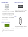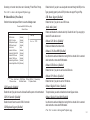
1
Table of Contents CHAPTER 1 Introduction..............................................................................................1-1 Package Check List..................................................................................1-1 Feature Summary......................................................................................1-2 Special Features........................................................................................1-3 Major Components...................................................................................1-5 Headers and Connectors...........................................................................1-7 Jumpers.....................................................................................................1-13 Rear Panel................................................................................................1-14 CHAPTER 2 Installing the CPU and the CPU fooling FAN..........................................2-1 Installing Memory Module.......................................................................2-1 Connecting IDE, Floppy and SATA cable..................................................2-2 Installing Motherboard in a case...............................................................2-2 Connecting IDE, Floppy & SATA Device..................................................2-3 Installing Expansion cards........................................................................2-3 Connecting the Power supply cable...........................................................2-4 Powering up..............................................................................................2-4 CHAPTER 3 Entering the BIOS Setup Menu.................................................................3-1 Updating and Recovering the BIOS...........................................................3-1 Using AWARD Flash to update your BIOS..........................................3-1 Using ECS EZ Flash to update your BIOS..........................................3-2 Using ECS Top-Hat Flash to recover your BIOS..................................3-3 The Main Menu.......................................................................................3-3 Standard CMOS Features............................................................3-3 Advanced BIOS Features............................................................3-5 Advanced Chipset Features.........................................................3-8 Integrated Peripherals.................................................................3-9 Power Management Setup.................................................................3-13 PNP/PCI Configurations..................................................................3-16 PC Health Status............................................................................3-17 Frequency/Voltage Control................................................................3-18 Load Fail-Safe Defaults...................................................................3-19 Load Optimized Defaults..................................................................3-19 Set Supervisor/User Password...........................................................3-19 Save & Exit Setup...........................................................................3-20 Exit Without Saving.........................................................................3-20 CHAPTER 4 Software CD Information.........................................................................4-1 Running the Software CD.........................................................................4-1 Setup Tab..................................................................................................4-1 Application Tab........................................................................................4-2 Read Me Tab............................................................................................4-2 Software Utilities Introduction.................................................................4-2 Multi-Language Translations Legal Notices Chapter 1 This chapter entails the newest technology and rich features on the Photon Extreme motherboard. Reference 1.1 1.2 1.3 1.4 1.5 1.6 1.7 1.8 Introduction....................................................1-1 Package Check List...........................................1-1 Feature Summary...........................................1-2 Special Features.............................................1-3 Major Components........................................1-5 Headers and Connectors................................1-7 Jumpers........................................................1-13 Rear Panel...................................................1-14 1.1 Introduction Thank you for choosing the ECS PF4 Extreme motherboard. 1.2 Package Check List Motherboard User’s Guide Installation CD SATA Power Cable Top Hat Flash I/O Shield Two Streamlined IDE & FDD Ribbon Cable Two SATA Cables Cross Over Cable The PF4 Extreme is the next generation of high performance motherboard designed to support the LGA775 socket Intel Pentiun4/Prescott Processors. This motherboard has an ATX form factor that uses a 6-layer printed circuit board and measures 305 mm x 244 mm. The PF4 Extreme motherboard is based on the Intel 915P(Grandsdale) Northbridge and ICH6 chipsets to set a new benchmark for the best desktop platform solution. Supporting up to 4 GB of system memory with DDR2 400/533 DDR DIMMs, high resolution graphics via PCI Expess ports, Dual LAN, USB 2.0, 8-channel audio, Digital S/PDIF in/out, SATA support and RAID function. USB+1394 PCI Bracket & housing *Accessories are subject to change with prior notice. 1-1 1.3 Feature Summary CPU Chipset Memory Expansion Slots Storage 1-2 • • • • • • LGA775 Socket for Intel Pentium4/Prescott processor FSB 800/533MHz Supports Hyper-Threading Technology Intel 915P & ICH6 North Bridge: Intel 915P South Bridge: Intel ICH6 • • • • • • • Dual-channel DDR memory architecture 4 x 240-pin DDR2 DIMM socket support up to 4 GB Supports DDR2 400/533 Non-ECC, unbuffered 1.8V DDR DIMMs 1 x PCI Express x16 2 x PCI Express x1 3 x PCI Slots • Supported by ICH6 - 2 x Ultra DMA100/66 devices - 4 x SATA devices • Supported by SiS180 - 2 x Ultra DMA133/100/66 devices - 2 x SATA devices - RAID 0, RAID 1, RAID 0+1 configuration IEEE 1394a • • VIA VT6307 IEEE1394a controller Supports 2 x IEEE1394a portrs Audio • • CMI9880 8-channel audio CODEC Compliant with Intel Azalia specification Dual LAN • • Marvel 88E8001 Gigabit LAN Controller Realtek8100C 10/100 Mbps Fast Ethernet Controller Rear panel I/O • • • • • • • • 1 x PS/2 keyboard connector 1 x PS/2 mouse connector 4 x USB ports 2 x RJ45 LAN connectors 1 x Serial port (COM1) 1 x Digital SPDIF out 1 x Digital SPDIF in Line-out/Line-in/Microphone in connectors BIOS features • Award BIOS with 4Mb Flash ROM Supports Plug and Play 1.0A, APM 1.2, Multi Boot, DMI Supports ACPI revision 1.0B specificaion Internal I/O • 1 x 24-pin ATX Power Supply Connector & 4-pin 12 V Connector • • 1.4 Special Features • • • • • • • • • • • • • Form Factor • • 1 x Floppy connector- supports 360K ~ 2.88M Bytes, 3 Mode FDDs or LS120 2 x IDE connectors 6 x Serial ATA connectors 2 x USB 2.0 headers support additional 4 USB ports 1 x 1394a header 1 x SMBus header 1 x Front panel switch/LED header 1 x Front panel audio header 1 x LPT header 1 x CHS1 header 1 x SMI1 header CD in header CPUFAN/NB_FAN/SYSFAN connectors ATX size 305mm x 244mm Extreme Power Device plug with USB-like ease! Upgrade your PC to Server-grade power now! Slash memory access time! One-key boot device selection! The best aluminum capacitors empowering! 6-layer PCB! Extreme Guardian Auto restart after power loss! PC protection tool kit! Awesome overclocking! A ‘time machine’ to protect and restore files! Uncompromising DVD audio quality! Become your own BIOS ‘doctor’! 1-3 Memory module alert! Fuzzy logic design for diagnosing PCI slots health! Extreme Link Add peripherals and consumer electronics devices! PCI 2.3 support! Smart LAN! All the USB 2.0 connectivity you’ll ever need! 1-4 More port options! Industrial-strength LAN power! Auto-negotiate your 10/ 100M LAN! Extreme Genius Color-coding for easy connections! Flash BIOS from Windows! Double digital audio! Rounded corners for strength and safety! Let your PC as a fileserver! Eliminate data highway roadblocks! Server Class Dual LAN for both Internet & Intranet! Ultra sound quality! An dust-proof auto shutter for optical connector! Clear & Clean! 1.5 Major Components 1. CPU socket LGA775 surface mount, Zero Insertion Force socket for Intel Pentium4/Prescott Processors support FSB 800/533 MHz that allows up to 6.4 GB/s data transfer rates. 2. Dual-channel DDR2 DIMM sockets These four 240-pin DIMM sockets support up to 4GB system memory using unbuffered DDR2 400/533 DDR DIMMs. 3. Super I/O (83627THF) controller The Winbond 83627THF Low Pin Count (LPC) interface provides the commonly used super I/O functionality. The chipset support a high performance floppy disk controller, a multi-mode parallel port, one serial port, a game port, the mouse and keyboard interface. 4. Northbridge controller 915P is a Memory Controller Hub (MCH) designed for use with the Pentium 4 processor in desktop platforms. It also supports PCI Express specification. 5. Flash ROM This 4Mb ROM contains the programmable BIOS program. 6. Southbridge controller The Intel ICH6 integrated peripheral controller supports various I/O functions including four Serial ATA connectors, dual channel UltraDMA100/66/33 master mode EIDE controller, up 1-5 to eight USB 2.0 ports, Azalia Audio interface, and PCI 2.3 interface. 7. PCI Express x16 (PCI-E1) slot This 915P has one x16 PCI Express slot, which is intended for an external PCI Express graphics card. 8. SiS 180 Serial ATA controller This motherboard incorporates the high performance SiS 180 IDE RAID controller, which supports RAID 0, RAID 1 and RAID 0+1 configuration. 9. PCI slots These three 32-bit PCI 2.3 expansion slots support bus master PCI cards like SCSI or LAN cards with 133MB/s maximum throughput. 10. IEEE 1394a controller The IEEE 1394a controller provides high-speed and flexible PC connectivity to a wide range of peripherals and devices compliant to IEEE 1394a standards. The IEEE 1394a interface allows up to 400Mbps tranfer rates. 11. PCI Express x1 (PCI-E2/PCI-E3) slots The two PCI Express x1 slots are fully compliant to the PCI Express Base Specification revision 1.0a 12. Audio CODEC The audio CODEC is compliant with Intel Azalia spec and supports 8-channel High Definition audio. 1-6 13. 10/100Mbps LAN Controller The 10/100Mbps LAN delivers a transfer rates up to 10/100 Mbps. 14. Gigabit LAN controller The Gigabit LAN controller delivers transfer rates up to 10/100/ 1000Mbps Ethernet connection. Ideal for handling large amounts of data such as video, audio and voice. 15. Cooling Accelerator The cooling accelerator supercharges airflow exchange between the chassis interior and exterior, keeping operating temperatures under control. a. Anti-Burn LED indicator When this LED is light up, do not remove the memory module from your DIMM slot or else your memory module will be damaged. b. PCI LED indicator The PCI LED indicates the PCI slot activity. These LEDs will stop blinking when add card has been installed. Blinking means no add card installed or add card was not properly installed. 1.6 Headers and Connectors 1. ATX12V This connector supplies the CPU operation voltage (Vcore). Don’t forget to connect the 4-pin ATX 12V connector, otherwise the system cannot boot up. 2. CPU_FAN1 (CPU Fan Connector, 4 pin) Please note, a proper installation of the CPU cooler is essential to prevent the CPU from running under abnormal condition or damaged by overheating. The CPU fan connector supports maximum current up to 600 mA. 1-7 3. ATX_POWER1(ATXPWR, 24 pin) AC power cord should only be connected to your power supply until after ATX power cable and other related devices are firmly connected to the motherboard. Make sure that your ATX12V power supply could provide 8A of 12V and at least 1A on the +5V standby. The minimum recommended voltage is 230W or 300W. If not, the system may become unstable or may not even boot up. 5. FDD1 (Floppy Connector, 34-1 pin, Black) Please connect the floppy drive ribbon cables to FDD. It supports 360K, 12M, 720K, 1.44M and 2.88M bytes floppy disk types. 6. Batter y 4. IDE 1 (IDE1 Connector, 40-1 pin, Green) This is supported by ICH6 South Bridge. Please connect the first hard disk to IDE 1. The streamline IDE cable must be the same side with the Pin 1. 1-8 Danger of explosion if battery is incorrectly replaced. Replace only with the same of equivalent type recommended by the manufacturer. 7. SYSFAN1/SYSFAN2/SYSFAN3(System Fan Connectors, 3 pin) 9. LPT (Onboard LPT port, 26-1 pin) If you installed wrong direction, the chip fan will not work. Sometimes will damage the chip fan. 8. SATA 1/2/3/4 (Serial ATA Connectors, 7 pin, Orange) This 25-pin port connects a parallel printer, a scanner, or other devices. 10. IDE 2 (IDE2 Connector/IDE RAID ATA133 Connector, 40-1 pin, Green) These next generation connectors are delivered by ICH6 South Bridge support the thin Serial ATA cables for Serial ATA hard disks. The current Serial ATA interface allows up to 150MB/s data transfer rate, faster than the standard parallel ATA with 133MB/s (UltraATA 133) This is supported by SiS180. The streamline IDE cable must be the same side with the Pin 1. This connector supports either RAID 0 or RAID 1 configuration through the onboard SiS180 controller. You can connect two UltraATA 133 hard disks to this connector and set up a disk array configuration. You may also set up the UltraATA 133 hard disks with 1-9 the Serial ATA hard disks on the Serial ATA RAID connectors to create a multi-RAID configuration. 13. PANEL1 (Front Panel Header, 10-1 pin) Notes: To install the OS, the CD-ROM must be installed on IDE1. You may as well connect the CD-ROM to IDE2, only after SiS180 driver is installed before you start using it. 11. CHS1 (Chassis Intrusion Detect header, 2 pin) The front panel connector provides a standard set of switch and LED connectors commonly found on ATX or micro-ATX cases. This header allows users to detect unauthorized intrusion to the case. It will alert users with a warning message when the case is turned on. 14. IR1 (Infrared header, 6-1 pin, Black) 12. SMI1 (System Management Interrupt header, 2 pin) This connector is for use with SMI hardware interrupt power management. 1-10 The motherboard supports an infrared (IR1) data port. Infrared ports allow the wireless exchange of information between your computer and similarly equipped devices such as printers, laptops, Personal Digital Assistants (PDAs), and other computers. 15. USB3/USB4 (Front USB Headers, 10-1 pin, Yellow) If the USB ports on the rear panel are inadequate, two USB headers are available for additional USB ports. The USB header complies with USB 2.0 specification that supports up to 480 Mbps connection speed. This speed advantage over the conventional 12 Mbps on USB 1.1. 17. SMB1 (SMBus Header, 6-1 pin) This connector allows you to connect SMBus (System Management Bus) devices. Devices communicate with an SMBus host and/or other SMBus devices using the SMBus interface. 18. CDIN1 (CD In Connector, 4 pin) 16. 1394A2 (10-1 pin Header, Orange) Connect CD-ROM or DVD-ROM audio out to the connector. Attach the 10-1 pin 1394 cable plug from the device to this connector. You may also connect a 1394-compliant internal hard disk to this connector. 1-11 19. AUDIO1 (Front Panel Audio Header, 10-1 pin) This is an interface for the Intel front panel audio cable that allows convenient connection and control of audio devices. Notes: 20. SATA 5/6 (Serial ATA RAID Connectors, 7 pin, Orange) These Serial ATA connectors support SATA hard disks that you may configure as a RAID set. Through the onboard SiS180 RAID controller you may create a RAID 0, RAID 1, RAID 0+1, or multiRAID configuration together with the RAID ATA133 connector. 21. NBFAN1 (Northbridge Fan Connector, 3 pin) If your front panel cable is seperated, please connect it to pin1 and pin3 or pin5 and pin7 to activate the MIC function. If you installed wrong direction, the chip fan will not work. Sometimes will damage the chip fan. 1-12 1.7 Jumpers 1. BIOS_WP1 (Flash Protect) This jumper enables you to prevent the BIOS from being updated (flashed). Open: Disable (Default) Short: Enable 2. JP1 (Clear CMOS) This jumper allows you to clear the Real Time Clock (RTC) RAM in CMOS. You can clear the CMOS memory of date, time, and system setup parameters by erasing the CMOS RAM data. Before clearing the CMOS data, make sure to turn the system off. 3. JP10 (Clear RTC) (Optional) This jumper allows you to clear the Real Time Clock (RTC) RAM in CMOS. 1-13 1.8 Rear Panel 1. PS/2 mouse port This 6-pin connector is for connecting PS/2 mouse. 2. RJ-45 port This port allows connection to a Local Area Network (LAN) through a network hub. It supports up to 10/100Mbps transfer rate. 3. RJ-45 port This port allows connection to a Local Area Network (LAN) through a network hub. It supports up to Gigabit tranfer rate. 4. Side Surround Jack * This jack connects a tape player or other audio sources. In 8-channel mode, the function of this jack is Side Surround speaker out. 5. Back Surround Jack * This jack connects a tape player or other audio sources. In 8-channel mode, the function of this jack is Back-Surround speaker out. 1-14 6. Center/Bass Jack * This jack connects a tape player or other audio sources. In 8-channel mode, the function of this jack is Center/Bass speaker out. 7. Front Out Jack * This jack connects a tape player or other audio sources. In 8-channel mode, the function of this jack is Front speaker out. 8. Optical S/PDIF output port This jack connects to external digital audio output devices. 9. Microphone in Jack * The function of the jack is microphone input. 10/11. USB 2.0 ports 3/4 These Universal Serial Bus (USB) ports are available for connecting USB 2.0 devices. 12. 1394_A1 port Use the 1394a port to connect any Firewire device. 13. S/PDIF input port This jack connects to external digital audio input devices. 14. Serial port This 9-pin COM1 port is for serial devices. 15. PS/2 keyboard port This 6-pin connector is for connecting PS/2 keyboard. The audio ports with a * sign can be changed to audio input or audio output by changing the driver utility setting. Chapter 2 This chapter explains the hardware setup procedure for this motherboard, such as installing the CPU, memory modules, expansion cards, as well as the jumpers Reference 2.1 2.2 2.3 2.4 2.5 2.6 2.7 2.8 Installing the CPU and the CPU cooling fan.......2-1 Installing Memory Module.................................2-1 Connecting IDE, Floppy and SATA cable...........2-2 Installing Motherboard in a case.........................2-2 Connecting IDE, Floppy & SATA Device...........2-3 Installing Expansion cards...................................2-3 Connecting the Power supply cable...................2-4 Powering up.......................................................2-4 2.1 Installing the CPU & the CPU cooling fan A. Unload the cap · Use thumb & forefinger to hold the lifting tab of the cap. · Lift the cap up and remove the cap completely from the socket. B. Open the load plate · Use thumb & forefinger to hold the hook of the lever, pushing down and pulling aside unlock it. · Lift up the lever. · Use thumb to open the load plate. Be careful not to touch the contacts. C. Install the CPU on the socket · Orientate CPU package to the socket. Make sure you match the triangle marker to the pin 1 location. D. Close the load plate · Slightly push down the load plate onto the tongue side, and hook the lever. · CPU is locked completely. E. Apply thermal grease on top of the CPU. F. Fasten the cooling fan supporting base onto the CPU socket on the motherboard. G. Make sure the CPU fan is plugged to the CPU fan connector. Please refer to the CPU cooling fan user’s manual for more detailed installation procedure. To achieve better airflow rates and heat dissipation, we suggest that you use a high quality fan with 3800 rpm at least. CPU fan and heatsink installation procedures may vary with the type of CPU fan/heatsink supplied. The form and size of fan/heatsink may also vary. 2.2 Installing Memory Module 1. Push the latches on each side of the DIMM slot down. 2. Check that the cutouts on the DIMM module edge connector match the notches in the DIMM slot. 3. Install the DIMM module into the slot and press it firmly down until it seats correctly. The slot latches are levered upwards and latch on to the edges of the DIMM. 2-1 Table A: Recommended dual-channel DDR2 configurations DIMM1 DIMM2 √ √ Notes: DIMM3 DIMM4 √ √ √ √ √ √ Dual Channel √ √ 2.4 Installing Motherboard in a case 1. Place the motherboard over the mounting brackets. 2. Secure the motherboard with screws where appropriate. √ When using dual channel mode, install only same (same density, DRAM technology and DRAM bus width) module for each dual channel. Memory module install into one or any four sockets will function in single channel mode. 2.3 Connecting IDE, Floppy and SATA cable 1. Connect the IDE/Floppy disk ribbon cable. Make sure the side of the cable with the red stripe on it is plugged into pin 1 side of the disk connector. 2. Connect the SATA cable to the SATA hard drive or the connector on the motherboard. IDE connector 2-2 FDD connector SATA connector 3. Double check to make sure that the underside of the motherboard is not touching the case or else shorting may occur and make sure that the slots and I/O connectors line up with the holes on the back of the case. 4. Case LED leads are labeled, connect the leads to the panel header on the motherboard. 2.5 Connecting IDE, Floppy & SATA Device 2.6 Installing Expansion cards 1. If installing two IDE devices on the same ribbon cable, one device must be set to “master” and the other to “slave.” Check the accompanying documents for the master/slave settings of IDE Devices, ie.: the hard disk and CD-ROM drives and then set their jumper caps accordingly. 2. Mount the drives in the case. 3. Connect the floppy disk ribbon cable and power cable. 4. Connect the IDE ribbon cable and power cable. 1. Remove the slot covers from the case where you will be installing the expansion cards. 2. Install your graphics card in the proper slot if your motherboard does not have integrated graphics. 3. Press the card firmly into the slot 4. Secure the card with the screw from step 1. 5. Install other expansion cards using the same procedure. IDE Hard Disk Floppy Disk Device SATA Hard Disk Graphics card PCI card 2-3 2.7 Connecting the Power supply cable The ATX power connector is keyed for proper insertion. There are two connectors for 4-pin and 24-pin ATX power cable. The plastic clip on the power connector should lock over the plastic tab on the motherboard power connector. Connecting 20/24-pin power cable Users please note that the 20-pin and 24-pin power cables can both be connected to the ATX1 connector. With the 20-pin power cable, just align the 20-pin power cable with the pin 1 of the ATX1 connector. However, using 20-pin power cable may cause the system to become unbootable or unstable because of insufficient electricity. Users please note that when installing 20pin power cable, the latche of power cable falls on the left side of the ATX1 connector latch, just as the picture shows. 20-pin power cable 2-4 Users please note that when installing 24pin power cable, the latches of power cable and the ATX1 match perfectly. 24-pin power cable Users please note that when installing 4-pin power cable, the latches of power cable and the ATX12 match perfectly. 4-pin ATX power connector 2.9 Powering up Turn on the power to the monitor and the computer. If necessary, format your hard disk drive and install an operating system. Chapter 3 In this chapter, you will learn how to adjust the BIOS (Basic Input and Output System) setup menus. It provides information on the system’s configuration status and options to setup system parameters. Reference 3.1 3.2 Entering the BIOS Setup Menu..........................3-1 Updating and Recovering the BIOS....................3-1 3.2-1 Using AWARD Flash to update your BIOS............3-1 3.2-2 Using ECS EZ Flash to update your BIOS...........3-2 3.2-3 Using ECS Top-Hat Flash to recover your BIOS..3-3 3.3 The Main Menu.................................................3-3 3.3-1 Standard CMOS Features........................................3-3 3.3-2 Advanced BIOS Features.........................................3-5 3.3-3 Advanced Chipset Features.....................................3-8 3.3-4 Integrated Peripherals..............................................3-9 3.3-5 Power Management Setup..................................3-13 3.3-6 PNP/PCI Configurations..........................................3-16 3.3-7 PC Health Status.......................................................3-17 3.3-8 Frequency/Voltage Control....................................3-18 3.3-9 Load Fail-Safe Defaults...........................................3-19 3.3-10 Load Optimized Defaults........................................3-19 3.3-11 Set Supervisor/User Password...............................3-19 3.3-12 Save & Exit Setup....................................................3-20 3.3-13 Exit Without Saving.................................................3-20 3.1 Entering the BIOS Setup Menu 3.2 Updating and Recovering the BIOS When you power on the system, BIOS enters the Power-On Self Test (POST) routines. POST is a series of built-in diagnostics performed by the BIOS. After the POST routines are completed, the following message appears: A standard configuration has already been set in the Setup Utility. However, if you encounter a configuration error or you need a better performance. You could attempt to update or recover your system BIOS. Press DEL to enter SETUP Pressing the delete key accesses the BIOS Setup Utility: Phoenix-AwardBIOS CMOS Setup Utility: Standard CMOS Features Frequency/Voltage Control Advanced BIOS Features Load Fail-Safe Defaults Advanced Chipset Features Load Optimized Defaults Integrated Peripherals Set Supervisor Password Power Mangement Setup Set User Password PnP/PCI Configurations Save & Exit Setup PC Health Status Exit Without Saving Esc: Quit F9: Menu in BIOS : Select Item F10: Save & Exit Setup Time, Date , Hard Disk Type... 3.2-1 Using AWARD Flash to update your BIOS 1. If your motherboard has an item called Firmware Write Protect in Advanced BIOS features, disable it. (Firmware Write Protect prevents BIOS from being overwritten). 2. Create a bootable system disk. (Refer to Windows online help for information on creating a bootable system disk.) 3. Use the Award Flash Utility from the ECS support CD and download the last BIOS file for this motherboard from ECS web site (www.ecs.com.tw). Copy these files to the system diskette you created in step 2. 4. Turn off your computer and insert the system diskette in your computer’s diskette drive. (You might need to run the Setup Utility and change the boot priority items on the Advanced BIOS Features Setup page, to force your computer to boot from the floppy diskette drive first.) 5. At the A:\ prompt, type the Flash Utility program name and press <Enter>. You see a screen similar to the following: 3-1 6. Type the filename of the new BIOS in the “File Name to Program” text box. Follow the onscreen directions to update the motherboard BIOS. 7. When the installation is complete, remove the floppy diskette from the diskette drive and restart your computer. If your motherboard has a Flash BIOS jumper, reset the jumper to protect the newly installed BIOS from being overwritten. 3.2-2 Using ECS EZ Flash to update your BIOS The ECS EZ Flash feature allows you to easily update the BIOS without having to go through the long process of booting from a diskette and using a DOS-based utility. 3. Select the “Flash” button. 4. The Utility will update the new BIOS into the motherboard Flash ROM. Note: EZ Flash only supports Windows 2000/XP. 1. Download the last BIOS file for this motherboard from ECS web site (www.ecs.com.tw). Copy these files to any storage device that you have. 2. Enable the utility from ECS support CD, then click the “Load” button and select the BIOS that you have downloaded in advance. 3-2 5. Click the “Reboot” button if you want to adopt the new BIOS or choose the “Cancel” button if you still want to use the previous BIOS. 3.2-3 Using ECS Top-Hat Flash to recover your BIOS 3.3 The Main Menu The ECS Top-Hat Flash kit allow you to restore BIOS from ECS website (www.ecs.com.tw) or ECS support CD, in case you current BIOS on the motherboard or get corrupted, please follow the procedures below to recover your BIOS. 1. Please find the BIOS ROM located on your motherboard. (Figure A) 2. Find the cut edge corner on the Flash ROM. (Figure B) 3. Find the cute edge corner on the Top Hat Flash. (Figure C) 4. Orient the cut edge Top Hat Flash to BIOS ROM’s and press the flash ROM into the lower socket of Top Hat Flash. (Figure D & E) 5. Then, power on your computer. The main menu of the Setup Utility displays a list of the options that are available. A highlight indicates which option is currently selected. Use the cursor arrow keys to move the highlight to other options. When an option is highlighted, execute the option by pressing <Enter>. Figure A Figure B Figure C Figure D Figure E 6. After the computer boots up, remove the Top Hat Flash. 7. Download the BIOS file from ECS web site (www.ecs.com.tw) or ECS support CD and use Flash Utility to reflash the original Flash ROM. 8. You can choose either AWARD Flash utility in DOS mode or ECS “EZ Flash Utility” in windows to reflash the BIOS. 3.3-1 Standard CMOS Features This option displays basic information about your system. Phoenix-AwardBIOS CMOS Setup Utility Standard CMOS Features Date (mm:dd:yy) Time (hh:mm:ss) IDE Channel 0 IDE Channel 0 IDE Channel 1 IDE Channel 1 Drive A Floppy 3 Mode Video Halt On Mon, May 17 2004 9 : 33 : 26 Master Slave Master Slave Support Base Memory Extended Memory Total Memory Item Help Menu Level Change the day, month, year and century [1.44M, 3.5 in.] [Disabled] [EGA/VGA] [All Errors] 640K 65535K 1024K : Move Enter: Select +/-/PU/PD:Value F10:Save ESC:Exit F1: General Help F5:Previous Values F6:Fail-Safe Defaults F7:Optimized Defaults Date and Time The Date and Time items show the current date and time on the computer. If you are running a Windows OS, these items are automatically updated whenever you make 3-3 changes to the Windows Date and Time Properties utility. IDE Devices [None] Your computer has two IDE channels (Primary and Secondary) and each channel can be installed with one or two devices (Master and Slave). Use these items to configure each device on the IDE channel. Press <Enter> to display the IDE submenu: Phoenix-AwardBIOS CMOS Setup Utility IDE Channel 0 Slave IDE HDD Auto-Detection [Press Enter] IDE Channel 0 Slave Access Mode [Auto] [Auto] Capacity 0MB Cylinder Head Precomp Landing Zone Sector 0 0 0 0 0 Item Help Menu Level To auto-detect the HDD’s size, head... on this channel : Move Enter: Select +/-/PU/PD:Value F10:Save ESC:Exit F1: General Help F5:Previous Values F6:Fail-Safe Defaults F7:Optimized Defaults Leave this item at Auto to enable the system to automatically detect and configure IDE devices on the channel. If it fails to find a device, change the value to Manual and then manually configure the drive by entering the characteristics of the drive in the items described below. Note: Before attempting to configure a hard disk drive, ensure that you have the configuration information supplied by the manufacturer of your hard drive. Incorrect settings can result in your system not recognizing the installed hard disk. Access Mode This item defines ways that can be used to access IDE hard disks such as LBA (Large Block Addressing). Leave this value at Auto and the system will automatically decide the fastest way to access the hard disk drive. Press <Esc> to return to the Standard CMOS Features page. Drive A [1.44M, 3.5in.] These items define the characteristics of any diskette drive attached to the system. You can connect one or two diskette drives. Floppy 3 Mode Support [Disabled] IDE HDD Auto-Detection Floppy 3 mode refers to a 3.5-inch diskette with a capacity of 1.2 MB. Floppy 3 Press <Enter> while this item is highlighted to prompt the Setup Utility to automatically detect and configure an IDE device on the IDE channel. mode is sometimes used in Japan. Note: If you are setting up a new hard disk drive that supports LBA mode, more than one line will appear in the parameter box. Choose that lists LBA for an LBA drive. 3-4 IDE Channel 0/1 Master/Slave Video [EGA/VGA] Thsi item defines the video mode of the system. This motherboard has a built-in VGA graphics system; you must leave this item at the default value. CPU Feature (Press Enter) Halt On [All Errors] This item defines the operation of the system POST (Power On Self Test) routine. You can use this item to select which types of errors in the POST are sufficient to halt the system. Base Memory, Extended Memory and Total Memory These items are automatically detected by the system at start up time. These are display-only fields. You cannot make chanages to these fields. 3.3-2 Advanced BIOS Features Scroll to this item and press <Enter> to view the following screen: Phoenix-AwardBIOS CMOS Setup Utility CPU Feature Delay Prior to Thermal Thermal Management TM2 Bus Ratio TM2 Bus VID Limit CPUID MaxVal [16 Min] [Thermal Monitor 1] [0X] [0.8375V] [Disabled] Item Help Menu Level This option defines advanced information about your system. Phoenix-AwardBIOS CMOS Setup Utility Advanced BIOS Features CPU Feature Hard Disk Boot Priority CPU L3 Cache Hyper-Threading Technology Quick Power On Self Test First Boot Device Second Boot Device Third Boot Device Boot Other Device Boot Up Floppy Seek Boot Up NumLock Status Gate A20 Option Typematic Rate Setting X Typematic Rate (Chars/Sec0 X Typematic Delay (Msec) Security Option APIC Mode [Press Enter] [Press Enter] [Enabled] [Enabled] [Enabled] [Floppy] [Hard Disk] [CDROM] [Enabled] [Disabled] [On] [Fast] [Disabled] 6 250 [Setup] [Enabled] Item Help Menu Level : Move Enter: Select +/-/PU/PD:Value F10:Save ESC:Exit F1: General Help F5:Previous Values F6:Fail-Safe Defaults F7:Optimized Defaults : Move Enter: Select +/-/PU/PD:Value F10:Save ESC:Exit F1: General Help F5:Previous Values F6:Fail-Safe Defaults F7:Optimized Defaults Delay Prior to Thermal [16 Min] Enables you to set the delay time before the CPU enters auto thermal mode. Thermal Management [Thermal Monitor 1] This item sets CPU’s thermal control rule to protect CPU from overheat. feature is only available when CPU supports Thermal Monitor 2. This TM2 Bus Ratio [0 X] This item helps you to set the frequency (bus ratio) of the throttled performance that will be initiated when the on die sensor goes from not hot to hot. You may set the bus 3-5 ration number from 0 to 255. CPU L3 Cache [Enabled] TM2 Bus VID [0.8375V] Some high-end processors support L3. If the CPU do support L3, you may set this item to enable or disable. Leave this item at the default value for better performance. This item helps you to set the voltage of the throttled performance that will be initiated when the on die sensor goes from not hot to hot. Limit CPUID MaxVal [Disabled] This item limits the CPUID maximum value. Enable this item to install WinNT. Leave this item at the default value for other OS. Hyper-Threading Technology [Enabled] This item is only available when the chipset supports Hyper-Threading and you are using a Hyper-Threading CPU. Quick Power On Self Test [Enabled] Enable this item to shorten the power on testing (POST) and have your system start up faster. You might like to enable this item after you are confident that your system hardware is operating smoothly. Press <Esc> to return to the Advanced BIOS Features page. Hard Disk Boot Priority (Press Enter) Scroll to this item and press <Enter> to view the following screen: Phoenix-AwardBIOS CMOS Setup Utility Hard Disk Boot Priority First/Second/Third Boot Device [Floppy/Hard Disk/CDROM] Use these three items to select the priority and order of the devices that your system searches for an operating system at start-up time. 1. 2. 3. 4. 5. 6. 7. 8. Pri.Master: Pri.Slave: Sec. Master: Sec. Slave: USBHDD0: USBHDD1: USBHDD2: Bootable Add-in Cards : Move F5:Previous Values 3-6 Item Help Boot Other Device [Enabled] Menu Level Use < > or < > to select a device, then press <+> to move it up, or <-> to move it down the list. Press <ESC> to exit this menu. PU/PD+/-/:Change Priority F6:Fail-Safe Defaults F10:Save ESC:Exit F7:Optimized Defaults When enabled, the system searches all other possible locations for an operating system if it fails to find one in the devices specified under the First, Second, and Third boot devices. Boot Up Floppy Seek [Disabled] If this item is enabled, it checks the size of the floppy disk drives at start-up time. You don’t need to enable this item unless you have a legacy diskete drive with 360K capacity. Boot Up NumLock Status [On] OS Select For DRAM > 64MB [Non-OS2] This item defines if the keyboard Num Lock key is active when your system is started. This item is only required if you have installed more than 64 MB of memory and you are running the OS/2 operating system. Otherwise, leave this item at the default. Gate A20 Option [Fast] HDD S.M.A.R.T Capability [Disabled] This item defines how the system handles legacy software that was written for an earlier generation of processors. Leave this item at the default value. The S.M.A.R.T. (Self-Monitoring, Analysis, and Reporting Technology) system is a diagnostics technology that monitors and predicts device performance S.M.A.R.T. software resides on both the disk drive and the host computer. Typematic Rate Setting [Disabled] If this item is enabled, you can use the following two items to set the typematic rate and the typematic delay settings for your keyboard. ♦ Typematic Rate (Chars/Sec): Use this item to define how many characters per second are generated by a held-down key. ♦ Typematic Delay (Msec): Use this item to define how many milliseconds must elapse before a held-down key begins generating repeat characters . Security Option [Setup] If you have installed password protection, this item defines if the password is required at system start up, or if it is only required when a user tries to enter the Setup Utility. APIC Mode [Enabled] The disk drive software monitors the internal performance of the motors, media, heads and electronics of the drive. The host software monitors the overall reliability status of the drive. If a device failure is predicted, the host software, through the Client WORKS S.M.A.R.T applet, warns the user of the impending condition and advises appropriate action to protect the data. Report No FDD For WIN 95 [Yes] Set this item to the default if you are running a system with no floppy drive and using Windows 95; this ensures compatibility with the Windows 95 logo certification. Full Screen LOGO Show [Enabled] When enabled, this will show a full screen company logo on the boot up screen. Select disabled when you want to show POST messages during boot up. Small Logo (EPA) Show [Disabled] Enables or disables the display of the EPA logo during boot. This item allows you to enable or disable the APIC (Advanced Programmable Interrupt Controller) mode. APIC provides symmetric multi-processing (SMP) for systems, allowing support for up to 60 processors. 3-7 3.3-3 Advanced Chipset Features CAS Latency Time [Auto] These items define critical timing parameters of the mainboard. You should leave the items on this page at their default values unless you are very familiar with the technical specifications of your system hardware. If you change the values incorrectly, this may cause fatal errors or instability into your system. DRAM RAS# to CAS# Delay [Auto] Phoenix-AwardBIOS CMOS Setup Utility Advanced Chipset Features DRAM Timing Selectable CAS Latency Time DRAM RAS# to CAS# Delay DRAM RAS# Precharge System BIOS Cacheable Video BIOS Cacheable PCI Express Root Port Func DDR Voltage [By SPD] [Auto] [Auto] [Auto] [Disabled] [Disabled] [Press Enter] [1.80V] Item Help Menu Level When synchronous DRAM is installed, the number of clock cycles of CAS latency depends on the DRAM timing. Do not reset this field from the default value specified by the system designer. This field lets you insert a timing delay between the CAS and RAS strobe signals, used when DRAM is written to, read from, or refreshed. Disabled gives faster performance; and Enabled gives more stable performance. DRAM RAS# Precharge [Auto] Select the number of CPU clocks allocated for the Row Address Strobe (RAS#) signal to accumulate its charge before the DRAM is refreshed. If insufficient time is allowed, refresh may be incomplete and data lost. System BIOS Cacheable [Disabled] This item allows the system to be cached in memory for faster execution. Enable this item for better performance. Video BIOS Cacheable [Disabled] This item allows the video BIOS to be cached in memory for faster execution. Enable these items for better performance. : Move Enter: Select +/-/PU/PD:Value F10:Save ESC:Exit F1: General Help F5:Previous Values F6:Fail-Safe Defaults F7:Optimized Defaults DRAM Timing Selectable [By SPD] The value in this field depends on performance parameters of the installed memory chips (DRAM). Do not change the value from the factory setting unless you install new memory that has a different performance rating than the original DRAMs. 3-8 PCI Express Root Port Func (Press Enter) Scroll to this item and press <Enter> to view the following screen: Phoenix-AwardBIOS CMOS Setup Utility PCI Express Root Port Func PCI Express Port 1 PCI Express Port 2 PCI Express Port 3 [Auto] [Auto] [Auto] 3.3-4 Integrated Peripherals These options display items that define the operation of peripheral components on the system’s input/output ports. Phoenix-AwardBIOS CMOS Setup Utility Integrated Peripherals Item Help Menu Level OnChip IDE Device Onboard Device SuperIO Device : Move F5:Previous Values PU/PD+/-/:Change Priority F6:Fail-Safe Defaults [Press Enter] [Press Enter] [Press Enter] Item Help Menu Level F10:Save ESC:Exit F7:Optimized Defaults PCI Express Port 1~3 [Auto] These items enable PCI transmission to a higher level. Press <Esc> to return to the Advanced Chipset Features page. : Move Enter: Select +/-/PU/PD:Value F10:Save ESC:Exit F1: General Help F5:Previous Values F6:Fail-Safe Defaults F7:Optimized Defaults DDR Voltage [1.80V] This item allows you to set the DDR SDRAM operating voltage. 3-9 IDE DMA transfer access [Enabled] OnChip IDE Device (Press Enter) Scroll to this item and press <Enter> to view the following screen: Phoenix-AwardBIOS CMOS Setup Utility OnChip IDE Device IDE HDD Block Mode ATA 66/100 Cable Msg IDE DMA transfer access On-Chip Primary PCI IDE IDE Primary Master PIO IDE Primary Slave PIO IDE Primary Master UDMA IDE Primary Slave UDMA On-Chip Secondary PCI IDE IDE Secondary Master PIO IDE Secondary Slave PIO IDE Secondary Master UDMA IDE Secondary Slave UDMA [Enabled] [Enabled] [Enabled] [Enabled] [Auto] [Auto] [Auto] [Auto] [Enabled] [Auto] [Auto] [Auto] [Auto] Item Help Menu Level If your IDE hard drive supports block mode select Enabled for automatic detection of the optimal number of block read/writes per sector the drive can support *** On-Chip Serial ATA Setting *** On-Chip Serial ATA [Disabled] PATA IDE Mode [Primary] SATA Port P1, P3 is Secondary : Move Enter: Select F5:Previous Values +/-/PU/PD:Value F10:Save ESC:Exit F1: General Help F6:Fail-Safe Defaults F7:Optimized Defaults On-Chip Primary/Secondary PCI IDE [Enabled] The integrated peripheral controller contains an IDE interface with support for two IDE channels. Select Enabled to activate each channel separately. IDE Primary/Secondary Master/Slave PIO [Auto] Each IDE channel supports a master device and a slave device. These four items let you assign which kind of PIO (Programmed Input/Output) is used by IDE devices. Choose Auto to let the system auto detect which PIO mode is best, or select a PIO mode from 0-4. IDE Primary/Secondary Master/Slave UDMA [Auto] Each IDE channel supports a master device and a slave device. This motherboard supports UltraDMA technology, which provides faster access to IDE devices. If you install a device that supports UltraDMA, change the appropriate item on this list to Auto. You may have to install the UltraDMA driver supplied with this motherboard in order to use an UltraDMA device. On-Chip Serial ATA [Disabled] Enable this field if your IDE hard drive supports block mode. Block mode enables BIOS to automatically detect the optimal number of block read and writes per sector that the drive can support and improves the speed of access to IDE devices. When set to Disabled, then disabled SATA controller; when set to Auto, then will be automatically arranged by BIOS; when set to Combined Mode, then PATA and SATA are combined. Maximum of 2 IDE drives in each channel. When set to Enhanced Mode, then enable both SATA and PATA. Maximum of 6 IDE drives are supported. When set to SATA only, then SATA is operating in legacy mode. ATA 66/100 Cable Msg [Enabled] PATA IDE Mode [Primary] This item enables or disables the display of the ATA 66/100 Cable MSG. This item is used to set the PATA IDE mode. When set to Primary, P1 and P3 are IDE HDD Block Mode [Enabled] 3-10 This item allows you to enabled the transfer access of the IDE DMA. Secondary; on the other hand, when set to Secondary, P0 and P2 are Primary. Press <Esc> to return to the Integrated Peripherals page. USB Mouse Support [Enabled] Onboard Device (Press Enter) Scroll to this item and press <Enter> to view the following screen: Phoenix-AwardBIOS CMOS Setup Utility Onboard Device USB Controller USB 2.0 Controller USB Keyboard Support USB Mouse Support Azalia Audio Onboard LAN Device Onboard LAN Boot ROM Onboard SATA Device Onboard 1394 Device Onboard GigaLAN Device Onboard GigaLAN Boot ROM [Enabled] [Enabled] [Enabled] [Enabled] [Auto] [Enabled] [Disabled] [Enabled] [Enabled] [Enabled] [Disabled] Enable this item if you plan to use a keyboard connected through the USB port in a l egacy operating system (such as DOS) that does not support Plug and Play. Item Help Menu Level Enable this item if you plan to use a USB mouse. Azalia Audio [Auto] Enables and disables the onboard audio chip. Disable this item if you are going to install a PCI audio add-on card. Onboard LAN Device [Enabled] Enables and disables the onboard LAN.. Onboard LAN Boot ROM [Disabled] Use this item to enable and disable the booting from the onboard LAN or a network add-in card with a remote boot ROM installed. Onboard SATA Device [Enabled] Enable this item if you plan to use the serial ATA device. Onboard 1394 Device [Enabled] : Move Enter: Select +/-/PU/PD:Value F10:Save ESC:Exit F1: General Help F5:Previous Values F6:Fail-Safe Defaults F7:Optimized Defaults Enable this item if you plan to use the 1394 device. USB Controller [Enabled] Onboard GigaLAN Device [Enabled] Enable this item if you plan to use the Universal Serial Bus ports on this motherboard. This option allows you enable or disable the onboard GigaLan device. USB 2.0 Controller [Enabled] Onboard GigaLAN Boot ROM [Enabled] Enable this item if want to use the USB 2.0 controller. Use this item to enable and disable the booting from the onboard LAN or a network add-in card with a remote boot ROM installed. Press <Esc> to return to the Integrated Peripherals page. USB Keyboard Support [Enabled] 3-11 SuperIO Device (Press Enter) Onboard FDC Controller [Enabled] Scroll to this item and press <Enter> to view the following screen: Phoenix-AwardBIOS CMOS Setup Utility SuperIO Device POWER ON Function KB Power ON Password Hot Key Power ON Onboard FDC Controller Onboard Serial Port1 UART 2 Mode Controller UART 2 Select RxD, TxD Active IR Transmission Delay UR2 Duplex Mode Use IR Pins Onboard Parallel Port Parallel Port Mode ECP Mode Use DMA [Hot KEY] [Enter] [Ctrl-F12] [Enabled] [3F8/IRQ4] [Disabled] [Normal] [Hi, Lo] [Enabled] [Half] [IR-Rx2Tx2] [378/IRQ7] [SPP] [3] Item Help Menu Level : Move Enter: Select +/-/PU/PD:Value F10:Save ESC:Exit F1: General Help F5:Previous Values F6:Fail-Safe Defaults F7:Optimized Defaults Onboard Serial Port 1 [3F8/IRQ4] This option is used to assign the I/O address and interrupt request (IRQ) for onboard serial port 1 (COM1). UART 2 Mode Controller [Disabled] When enabled, this item activates the onboard infrared feature and sets the second serial UART to support the infrared module connector on the mainboard. Enabling this field disables the onboard COM2 connector. UART 2 Select [Normal] This field is available if the Onboard Serial Port 2 field is set to any option but “Disabled.” UART Mode Select enables you to select the infrared communication protocol—Normal, IrDA, ASKIR or SCR This feature allows you to set the method by which your system can be turned on. The UART mode setting depends on which type of infrared module is used in the system. When set to “SCR,” “ASKIR” or “IrDA,” the UART mode is used to support the infrared module connected on the mainboard. If this option is not set to “Normal,” a device connected to the COM2 port will no longer work. KB Power ON Password [Enter] RxD, TxD Active [Hi, Lo] When the POWER ON Function is set to Password, use this item to set the password. This feature enables you to set the IR reception/transmission polarity as High or Low. Hot Key Poewr ON [Ctrl-F12] IR Transmission Delay [Enabled] When the POWER ON Function is set to Hot KEY, use this item to set the hot key combination that turns on the system. This field enables you to set the whether the IR transmission rate will be delayed while converting to receiving mode. POWER ON Function [Hot KEY] 3-12 Select Enabled if your system has a floppy disk controller (FDC) installed on the system board and you wish to use it. If you install an add-in FDC or the system has no floppy drive, select Disabled in this field. UR2 Duplex Mode [Half] This field is available when UART 2 Mode is set to either ASKIR or IrDA. This item enables you to determine the infrared function of the onboard infrared chip. The options are Full and Half (default). Full-duplex means that you can transmit and send information simultaneously. Halfduplex is the transmission of data in both directions, but only one direction at a time. Use IR Pins [IR-Rx2Tx2] Please consilt your IR peripheral documentation to select the correct setting of the TxD and RxD signals. Onboard Parallel Port (378/IRQ7) This option is used to assign the I/O address and interrupt request (IRQ) for the onboard parallel port. Parallel Port Mode (ECP) Enables you to set the data transfer protocol for your parallel port. There are four options: SPP (Standard Parallel Port), EPP (Enhanced Parallel Port), ECP (Extended Capabilities Port) and ECP+EPP. SPP allows data output only. Extended Capabilities Port (ECP) and Enhanced Parallel Port (EPP) are bi-directional modes, allowing both data input and output. ECP and EPP modes are only supported with EPP- and ECP-aware peripherals. ECP Mode Use DMA (3) When the onboard parallel port is set to ECP mode, the parallel port can use DMA 3 or DMA 1. 3.3-5 Power Management Setup This option lets you control system power management. The system has various power-saving modes including powering down the hard disk, turning off the video, suspending to RAM, and software power down that allows the system to be automatically resumed by certain events. Phoenix-AwardBIOS CMOS Setup Utility Power Management Setup PCI Express PM Function ACPI Suspend Type Run VGABIOS if S3 Resume Video Off Method Video Off In Suspend Suspend Type MODEM Use IRQ Suspend Mode HDD Power Down Soft-off by PWR-BTTN Resume by PCI PME Resume by PCI-E PME Resume by Ring Resume by USB (S3) Resume by Alarm *Date (of Month) Alarm *Time (hh:mm:ss) Alarm [Press Enter] [S3(STR)] [Auto] [DPMS] [Yes] [Stop Grant] [3] [Disabled] [Disabled] [Instant-off] [Enabled] [Enabled] [Disabled] [Disabled] [Disabled] 0 0:0:0 Item Help Menu Level **Reload Global Timer Events** Primary IDE 0 [Disabled] : Move Enter: Select +/-/PU/PD:Value F10:Save ESC:Exit F1: General Help F5:Previous Values F6:Fail-Safe Defaults F7:Optimized Defaults Press <Esc> to return to the Integrated Peripherals page. 3-13 PCI Express PM Function (Press Enter) Scroll to this item and press <Enter> to view the following screen: Phoenix-AwardBIOS CMOS Setup Utility PCI Express PM Function PCI Express PME [Enabled] Item Help Menu Level ACPI Suspend Type [S3(STR)] Use this item to define how your system suspends. In the default, S3 (STR), the suspend mode is a suspend to RAM, i.e., the system shuts down with the exception of a refresh current to the system memory. If you select S1 (POS), the suspend mode is equivalent to a software power down. Run VGABIOS if S3 Resume [Auto] This item allows the system to initialize the VGA BIOS from S3 (Suspend to RAM) sleep state. Video Off Method [DPMS] This item defines how the video is powered down to save power. This item is set to DPMS (Display Power Management Software) by default. Video Off In Suspend [Yes] : Move F5:Previous Values PU/PD+/-/:Change Priority F6:Fail-Safe Defaults F10:Save ESC:Exit F7:Optimized Defaults This option defines if the video is powered down when the system is put into suspend mode. PCI Express PME [Enabled] Suspend Type [Stop Grant] Use this item to enable PCI activity to wake up the system from a power saving mode. If this item is set to the default Stop Grant, the CPU will go into Idle Mode during power saving mode. Press <Esc> to return to the Power Management page. MODEM Use IRQ [3] If you want an incoming call on a modem to automatically resume the system from a power-saving mode, use this item to specify the interrupt request line (IRQ) that is used by the modem. You might have to connect the fax/modem to motherboard Wake On Modem connector for this feature to work. Suspend Mode [Disabled] 3-14 The CPU clock will be stopped and the video signal will be suspended if no Power Management events occur for a specified length of time. Full power function will return when a Power Management event is detected. Options are from 1 Min to 1 Hour and Disable. HDD Power Down [Disabled] The IDE hard drive will spin down if it is not accessed within a specified length of time. Options are from 1 Min to 15 Min and Disable. Soft-Off by PWR-BTTN [Instant-Off] Under ACPI (Advanced Configuration and Power management Interface) you can create a software power down. In a software power down, the system can be resumed by Wake Up Alarms. This item lets you install a software power down that is controlled by the power button on your system. If the item is set to Instant-Off, then the power button causes a software power down. If the item is set to Delay 4 Sec. then you have to hold the power button down for four seconds to cause a software power down. Resume by PCI PME [Enabled] This item specifies whether the system will be awakened from power saving modes when activity or input signal of the specified hardware peripheral or component is detected. Resume by PCI-E PME [Enabled] This item specifies whether the system will be awakened from power saving modes when activity or input signal of the specified hardware peripheral or component is detected. Resume by Ring [Disabled] Resume by USB(S3) [Disabled] This option allows the activity of the USB devices (keyboard and mouse) to wake-up the system from S3 sleep state. Resume by Alarm [Disabled] When set to Enabled, additional fields become available and you can set the date (day of the month), hour, minute and second to turn on your system. When set to 0 (zero) for the day of the month, the alarm will power on your system every day at the specified time. **Reload Global Timer Events** Global Timer (power management) events are I/O events whose occurrence can prevent the system from entering a power saving mode or can awaken the system from such a mode. In effect, the system remains alert for anything that occurs to a device that is configured as Enabled, even when the system is in a power-down mode. Primary IDE0/1 [Disabled] When these items are enabled, the system will restart the power-saving timeout counters when any activity is detected on any of the drives or devices on the primary or secondary IDE channels. Secondary IDE0/1 [Disabled] When this item is enabled, the system will restart the power-saving timeout counters when any activity is detected on the floppy disk drive, serial ports, or the parallel port. Power on After Power-fail [Off] This item enables your computer to automatically restart or return to its last operating. An input signal on the serial Ring Indicator (RI) line (in other words, an incoming call on the modem) awakens the system from a soft off state. 3-15 3.3-6 PNP/PCI Configurations Init Display First [PCI Slot] These options configure how PnP (Plug and Play) and PCI expansion cards operate in your system. Both the the ISA and PCI buses on the motherboard use system IRQs (Interrup ReQuests) and DMAs (Direct Memory Access). You must set up the IRQ and DMA assignments correctly through the PnP/PCI Configurations Setup utility for the motherboard to work properly. Selecting PnP/PCI Configurations on the main program screen displays this menu: Phoenix-AwardBIOS CMOS Setup Utility Use this item to specify the initial display to be the PCI slot or the graphics chip integrated on the motherboard. PnP/PCI Configurations Init Display First Reset Configuration Data [PCI Slot] [Disabled] Item Help Menu Level Resources Controlled By X IRQ Resources PCI/VGA Palette Snoop Assign IRQ For USB INT Pin 1 Assignment INT Pin 2 Assignment INT Pin 3 Assignment INT Pin 4 Assignment INT Pin 5 Assignment INT Pin 6 Assignment INT Pin 7 Assignment INT Pin 8 Assignment [Auto(ESCD)] Press Enter [Disabled] [Enabled] [Auto] [Auto] [Auto] [Auto] [Auto] [Auto] [Auto] [Auto] Reset Configuration Data [Disabled] If your enable this item and restart the system, any Plug and Play configuration data stored in the BIOS Setup is cleared from memory. Resources Controlled By [Auto (ESCD)] You should leave this item at the default Auto (ESCD). Under this setting, the system dynamically allocates resources to Plug and Play devices as they are required. If you can’t get a legacy ISA expension card to work properly, you might be able to solve the problem by changing this item to Manual, and them opening up the IRQ Resources submenu. • IRQ Resources (Press Enter): In the IRQ Resources submenu, if you assign an IRQ to Legacy ISA, then that Interrupt Request Line is reserved for a legacy ISA expansion card. Press <Esc> to close the IRQ Resources sub-menu. In the Memory Resources sub menu, use the first item Reserved. Memory Base to set the start address of the memory you want to reserve for the ISA expansion card. Use the second item Reserved Memory Length to set the amount of reserved memory. Press <Esc> to close the Memory Resources sub-menu. PCI/VGA Palette Snoop [Disabled] : Move Enter: Select +/-/PU/PD:Value F10:Save ESC:Exit F1: General Help F5:Previous Values F6:Fail-Safe Defaults F7:Optimized Defaults 3-16 This item is designed to overcome problem that can be caused by some nonstandard VGA cards. This board includes a built-in VGA system that does not required palette snooping so you must leave this item disabled. Case Open Warning [Disabled] Assign IRQ For USB [Enabled] This item enables or disables the warning if the case is opened up, and the item below indicates the current the status of the case. Names the interrupt request (IRQ) line assigned to the USB on your system. Activity of the selected IRQ always awakens the system. INT Pin 1-8 Assignment [Auto] Identify the interrupt request (IRQ) line assigned to the USB on your system. Activity of the selected IRQ always awakens the system. 3.3-7 PC Health Status On motherboards that support hardware monitoring, this item lets you monitor the parameters for critical voltages, temperatures and fan speeds. Phoenix-AwardBIOS CMOS Setup Utility PC Health Status X Case Open Warning Case has been Shutdown Temperature Current System Temp Current CPU1 Temperature NBFAN1 CPU FAN CAS FAN CPU Vcore 1.5V 3.3V Smart CPUFan Function CPUFan Tolerance Value [Disabled] CLOSING [Disabled] Item Help Menu Level Shutdown Temperature [Disabled] Enables you to set the maximum temperature the system can reach before powering down. System Component Characteristics These fields provide you with information about the systems current operating status. You cannot make changes to these fields. • Current System Temp • Current CPU1 Temperature • NB FAN Speed • CPU FAN SPeed • CAS FAN Speed • CPU Vcore • 1.5V • 3.3V Smart CPUFan Function [Disabled] [Disabled] 5 This item enables users to set to which Celsius degree when the Smart Fan2 start functioning. The default value is 40°C to 104°C. CPUFan Tolerance Value [5] : Move Enter: Select F5:Previous Values +/-/PU/PD:Value F10:Save ESC:Exit F1: General Help F6:Fail-Safe Defaults F7:Optimized Defaults This item helps you to adjust the frequency of Smart Fan. 3-17 3.3-8 Frequency/Voltage Control Example: This item enables you to set the clock speed and system bus for your system. The clock speed and system bus are determined by the kind of processor you have installed in your system. AGP Voltage [1.500 V] Phoenix-AwardBIOS CMOS Setup Utility Frequency/Voltage Control X CPU Clock Ratio AGP Voltage CPU Voltage Control CPU Core Voltage Auto Detect PCI Clk Spread Spectrum PCI EX/PCI Clock CPU Clock [8X] [1.500V] [By Auto] 1.1125V [Enabled] [Disabled] [Asyn] [200MHz] Item Help Menu Level CPU Clock Ratio 8 CPU Clock X200 Installed CPU Clock Speed 1600 MHz This item regulates the voltage delivered to the AGP. CPU Voltage Control [By Auto] If you are manually configuring the CPU clock, use this item to set the CPU voltage for more stability. But we recommend the users keep this item to By Auto. • CPU Core Voltage: Enables you to auto-detect the CPU core voltage. Auto Detect PCI Clk [Enabled] When this item is enabled, BIOS will disable the clock signal of free PCI slots. Spread Spectrum [Disabled] If you enable spread spectrum, it can significantly reduce the EMI (Electro-Magnetic Interference) generated by the system. : Move Enter: Select F5:Previous Values +/-/PU/PD:Value F10:Save ESC:Exit F1: General Help F6:Fail-Safe Defaults F7:Optimized Defaults CPU Clock Ratio [8X] Enable you to set the CPU clock. The CPU colck ratio times the CPU Host/ PCI Clock should equal the core speed of the installed processor. (For unlock Ratio CPU only.) 3-18 PCI EX/PCI Clock [Asyn] This item correlates to CPU Clock item; when set to Asyn, PCI EX/PCI Clock and CPU Clock will not operate at the same clock; when set to Sync, PCI EX/PCI Clock and CPU Clock will operate at the same clock. CPU Clock[200MHz] This item allows you to adjust the CPU clock to 200MHz. You can key-in the numbers within the range to make a precise and ideal adjustment. 3.3-9 Load Fail-Safe Defaults 3.3-11 Set Supervisor/User Password This option opens a dialog box that lets you install fail-safe defaults for all appropriate items in the Setup Utility: Press <Y> and the <Enter> to install the defaults. Press <N> and then <Enter> to not install the defaults. The fail-safe defaults place no great demands on the system and are generally stable. If your system is not functioning correctly, try installing the fail-safe defaults as a first step in getting your system working properly again. If you only want to install fail-safe defaults for a specific option, select and display that option, and then press <F6>. When this function is selected, the following message appears at the center of the screen to assist you in creating a password. 3.3-10 Load Optimized Defaults This option opens a dialog box that lets you install optimized defaults for all appropriate items in the Setup Utility. Press <Y> and then <Enter> to install the defaults. Press <N> and then <Enter> to not install the defaults. The optimized defaults place demands on the system that may be greater than the performance level of the components, such as the CPU and the memory. When your hardware does not support the “Optimized Defaults”, fatal system errors or instability may occur. If you only want to install setup defaults for a specific option, select and display that option, and then press <F7>. ENTER PASSWORD Type the password, up to eight characters, and press <Enter>. The password typed now will clear any previously entered password from CMOS memory. You will be asked to confirm the password. Type the password again and press <Enter>. You may also press <Esc> to abort the selection. To disable password, just press <Enter> when you are prompted to enter password. A message will confirm the password being disabled. Once the password is disabled, the system will boot and you can enter BIOS Setup freely. PASSWORD DISABLED If you have selected “System” in “Security Option” of “BIOS Features Setup” menu, you will be prompted for the password every time the system reboots or any time you try to enter BIOS Setup. If you have selected “Setup” at “Security Option” from “BIOS Features Setup” menu, you will be prompted for the password only when you enter BIOS Setup. Users please remain the factory BIOS default setting of “Load Optimized Defaults” when install Operation System onto your system. 3-19 Supervisor Password has higher priority than User Password. You can use Supervisor Password when booting the system or entering BIOS Setup to modify all settings. Also you can use User Password when booting the system or entering BIOS Setup but can not modify any setting if Supervisor Password is enabled. 3.3-12 Save & Exit Setup Highlight this item and press <Enter> to save the changes that you have made in the Setup Utility and exit the Setup Utility. When the Save and Exit dialog box appears, press <Y> to save and exit, or press <N> to return to the main menu. 3.3-13 Exit Without Saving Highlight this item and press <Enter> to discard any changes that you have made in the Setup Utility and exit the Setup Utility. When the Exit Without Saving dialog box appears, press <Y> to discard changes and exit, or press <N> to return to the main menu. Note: If you have made settings that you do not want to save, use the “Exit Without Saving” item and press <Y> to discard any changes you have made. 3-20 Chapter 4 This chapter delivers contents of the ECS support CD. Reference 4.1 4.2 4.3 4.4 4.5 4.6 Software CD Information...................................4-1 Running the Software CD..................................4-1 Setup Tab..........................................................4-1 Application Tab..................................................4-2 Read Me Tab....................................................4-2 Software Utilities Introduction............................4-2 4.1 Software CD Information 4.3 Setup Tab The support software CD-ROM that is included in the motherboard package contains all the drivers and utility programs needed to properly run the bundled products. Below you can find a brief description of each software program, and the location for your motherboard version. More information on some programs is available in a README file, located in the same directory as the software. The setup tab shows three buttons - Setup, Browse CD, Exit. Setup button: Click the Setup button to run the software installation program. Select from the menu which software you want to install. 1. Click Setup. The installation program begins: Note: Never try to install software from a folder that is not specified for use with your motherboard. 4.2 Running the Software CD To begin using the software CD, simply insert the CD into your CD-ROM drive. The CD automatically display the multimedia if auto run is enable in your computer. Note: The following screens are examples only. The screens and driver lists will be different according to the motherboard you are installing. The motherboard identification is located in the upper left-hand corner. 4-1 2. Click Next. The following screen appears: 4. Follow the instructions on the screen to install the items. Drivers and software are automatically installed in sequence. Follow the onscreen instructions, confirm commands and allow the computer to restart a few times to complete the installation. Browse CD button: The Browse CD button is the standard Windows Exit button: 3. Check the box next to the items you want to install. The default options are recommended. command that allows you to open Windows Explorer and show the contents of the support CD. The Exit button closes the Auto Setup window. 4.4 Application Tab Lists the software utilities that are available on the CD. 4.5 Read Me Tab Displays the path for all software and drivers available on the CD. 4.6 Software Utilities Introduction AWARD Flash Memory Utility This utility lets you erase the system BIOS stored on a Flash Memory chip on the motherboard, and lets you copy an updated version of the BIOS to the chip. Proceed with caution when using this program. If you 4-2 erase the current BIOS and fail to write a new BIOS, or write a new WinCinema BIOS that is incorrect, your system will malfunction. Refer to Chapter 3 “Using BIOS” for more information. WinFlash Utility The AWARD WinFlash utility is a Windows version of the DOS Award BIOS flash writer utility. The utility enables you to flash the system BIOS stored on a Flash Memory chip on the motherboard while in a Windows environment. This utility is currently available for WINXP\ME\2000\ 98SE. To install the WinFlash utility, rin WINFLASH.EXE from the following directory: \UTILITY\WINFLASH I’m InTouch I’m InTouch remote access software allows you to login and work on your far-away computer, just as if you were sitting behind it! Run programs, transfer files, manage e-mail, contacts and calendar events. With I’m InTouch, you always have access to your PC and the important information and programs that you need. MediaRing Talk - Telephony Software Go to \UTILITY\MEDIARING EZ NET and run SETUP 331.EXE to install the MediaRing Talk voice modem software for the built-in modem. WinDVD Creator Plus WinDVD Creator Plus is designed for people who want to make their own DVDs but who don’t want to learn complicated programs. By taking you through 4 DVD-making steps, WinDVD Creator Plus walks you through capturing video, editing it, adding titles, transitions, effects, music, DVD menus and finally burning the finished product. User also can direct-burn to DVD when DVD burner is available. WinDVD WinDVD is the world’s most popular DVD player and supports over 30 new features and enhancements such as improved picture quality, easier-to-use Time-Stretching, MP3 playback, and Video Desktop - which lets you watch movies under your desktop icons while you work or check email. WinRIP WinRIP lets you record, store, organize, and enjoy you music collection on your PC, CD player, and portable player. Organize your Music Galleryand create your own playlists. You can switch between simple Player mode or full-featured Jukebox mode. 4-3 4-4 Pro Magic Plus This amazing software not only provides users with convenient and instant restoration of your computer, but also restores within seconds important data back to the preferred state at a specific point in time. Pro Magic also combines several other functions including anti-virus, backup, uninstall software and multi-booting to satisfy all your system protection needs. DPU (Data Process Utility) Specially designed for file protection, security and management this DPU or data processing utility insures the safety of important data through complete file restoration, eliminating file damage even in case of improper operation. User can freely edit original files after a set restore time point. The DPU can even restore even deleted files. Adobe Reader This item install the Adobe Acrobat Reader. The Acrobat Reader software is for viewing files saved in Portable Document Format (PDF). Smart LAN The motherboard support Marvell Virtual Cable Tester (VCT) technology. It enables end users to remotely diagnose the quality and characteristics of the attached cable. With this feature it is possible to detect and report potential cabling issues such as cable opens, cable shorts, and impedance mismatches. The distance of the fault can be reported within one meter. Show Shifter ShowShifter, the award winning software, combines viewing TV, video, CD, MP3 and digital pictures into one easy to use application. With a little help from Showshifter your PC will be the ultimate home media center. Extreme Utilities Omni-Guardian Omni-Guardian is a self-diagnostic utility for PC system. It will protect PC hardware by monitoring several critical items including power supply voltage, CPU Fan speed, and CPU & System temperature. These are all important to Windows System. Some errors maybe result in permanent hurt of your system. User could set the reasonable range. Once when system monitors some being out of range, an obvious warning or beeping message will remind users to make a proper treatment. Omni-Guardian only supports under Window 2000/XP. EZ-Flash EZ-Flash provide users an easy-to-use tool which can maintain the BIOS easily. Also, it has two major functions, one is to save the current BIOS, the other is to update a new BIOS. EZ-Flash only supports under Windors 2000/XP. CPU • • • Socket LGA775 pour processeur Intel Pentium4/Prescott FSB 800/533MHz Prise en charge de la Technologie Hyper-Threading IEEE 1394a • • Contrôleur VIA VT6307 IEEE1394a Prend en charge 2 x ports IEEE1394a Chipset • • • Intel 915P & ICH6 North Bridge: Intel 915P South Bridge: Intel ICH6 Audio • • CODEC audio 8-canaux CMI9880 Conforme aux spécifications Intel Azalia Mémoire • • LAN Double • • Contrôleur LAN Gigabit Marvel 88E8001 Contrôleur Fast Ethernet 10/100 Mbps Realtek8100C • • Architecture mémoire DDR double canal 4 x sockets DIMM DDR2 240 broches prenant en charge jusqu’à 4 Go Prend en charge les DDR2 400/533 DIMMs DDR de 1,8V sans tampon, Non-ECC Options d’extension • • • 1 x PCI Express x16 2 x PCI Express x1 3 x logements PCI E/S du panneau arrière Stockage • Pris en charge par ICH6 - 2 x périphériques Ultra DMA100/66 - 4 x périphériques SATA Pris en charge par SiS180 - 2 x périphériques Ultra DMA133/100/66 - 2 x périphériques SATA - Configuration RAID 0, RAID 1, RAID 0+1 • • • • • • • • 1 x connecteur de clavier PS/2 1 x connecteur souris PS/2 4 x ports USB 2 x connecteurs LAN RJ45 1 x port Série (COM1) 1 x sortie SPDIF numérique 1 x entrée SPDIF numérique Connecteurs Sortie Ligne/Entrée Ligne/Microphone • Caractéristi- • ques du BIOS • • E/S interne • Award BIOS avec ROM Flash de 4Mb Prend en charge Plug & Play 1.0A, APM 1.2, Multi Boot, DMI Prend en charge les spécifications 1.0B révision ACPI 1 x Connecteur d’alimentation ATX 24 broches & Connecteur 12 V 4 broches Français Résumé des caractéristiques Français • Facteur de Forme • • • • • • • • • • • • 1 x connecteur de lecteur de disquette- prenant en charge 360K ~ 2,88M octets, 3 Lecteurs de disquettes Modes ou LS120 2 x connecteurs IDE 6 x connecteurs ATA Série 2 x embases USB 2.0 supportant 4 ports USB supplémentaires 1 x embase 1394a 1 x embase SMBus 1 x embase de commutateur/LED de panneau avant 1 x embase audio de panneau avant 1 x embase LPT 1 x embase CHS1 1 x embase SMI1 Embase entrée CD Connecteurs CPUFAN/NB_FAN/SYSFAN • • Taille ATX 305mm x 244mm CPU • • • LGA775 Sockel für Intel Pentium4/Prescott Prozessor FSB 800/533 MHz Unterstützt Hyper-Threading Technologie Chipsatz • • • Intel 915P & ICH6 North Bridge: Intel 915P South Bridge: Intel ICH6 Arbeitsspeicher • • • • Dual-Kanal DDR Speicherarchitektur 4 x 240-Pin DDR2 DIMM Sockel, unterstützt bis zu 4 GB Unterstützt DDR2 400/533 Unterstützt Nicht-ECC, ungepufferte 1,8V DDR DIMMs • Erweiterungsmöglichkeiten • • Speicher • • 1 x PCI Express x16 2 x PCI Express x1 3 x PCI Steckplätze Unterstützt durch einen ICH6 - 2 x Ultra DMA100/66 Geräte - 4 x SATA Geräte Unterstützt durch einen SiS180 -2 x Ultra DMA133/100/66 Geräte -2 x SATA Geräte -RAID 0, RAID 1, RAID 0+1 Konfiguration IEEE 1394a • • VIA VT6307 IEEE1394a Controller Unterstützt 2 x IEEE1394a Anschlüsse Audio • • CMI9880 8-Kanal Audio CODEC Entspricht Intel Azalia Spezifikation Dual LAN • • Marvel 88E8001 Gigabit LAN Controller Realtek8100C 10/100 Mbps Fast Ethernet Controller Rear panel I/O • • • • • • • • 1 x PS/2 Tastaturanschluss 1 x PS/2 Mausanschluss 4 x USB Anschlüsse 2 x RJ45 LAN Anschlüsse 1 x Seriellanschluss (COM1) 1 x Digital SPDIF Ausgang 1 x Digital SPDIF Eingang Line-out/Line-in/Microphone in Anschlüsse BIOS Merkmale • • • Award BIOS mit 4Mb Flash ROM Unterstützt Plug und Play 1.0A, APM 1.2, Multi Boot, DMI Unterstützt ACPI Revision 1.0B Spezifikation Internes I/O • 1 x 24-Pin ATX Netzteilanschluss & 4-Pin 12 V Anschluss Deutsch Zusammenfassung der Merkmale Deutsch • Formfaktor • • • • • • • • • • • • 1 x Floppylaufwerkanschluss, unterstützt 360K ~ 2.88M Bytes, 3 Modus Festplatten oder LS120 2 x IDE Anschlüsse 6 x Seriell ATA Anschluss 2 x USB 2.0 Anschluss, unterstützt zusätzlich 4 USB Anschluss 1 x 1394a Anschluss 1 x SMBus Anschluss 1 x Schalter in der Frontabdeckung/LED-Anschluss 1 x Audioanschluss in der Frontabdeckung 1 x LPT Anschluss 1 x CHS1 Anschluss 1 x SMI1 Anschluss CD-Einganganschluss CPUFAN/NB_FAN/SYSFAN Anschlüsse • • ATX-Größe 305mm x 244mm • • • • • • LGA775 Socket per processore Intel Pentium4/Prescott FSB 800/533 MHz Supportp di Tecnologia Hyper-Threadig Intel 915P & ICH6 North Bridge: Intel 915P South Bridge: Intel ICH6 • • • • Dual-channel DDR memory architecture 4 x 240-pin DDR2 DIMM socket che supportano sino a 4 GB Supporta DDR2 400/533 Supporta Non-ECC, unbuffered 1,8V DDR DIMMs Opzioni d’espansione • • • 1 x PCI Express x16 2 x PCI Express x1 3 x slots PCI Deposito • Supportato da ICH6 - 2 x dispositivi Ultra DMA100/66 - 4 x dispositivi SATA Supportato da SiS180 - 2 x dispositivi Ultra DMA133/100/66 - 2 x dispositivi SATA -configurazione RAID 0, RAID 1, RAID 0+1 CPU Chipset Memoria • IEEE 1394a • • Controller VIA VT6307 IEEE1394a Supporta 2 x porte IEEE1394a Audio • • CMI9880 8-canale audio CODEC Compatibile con le specifiche Intel Azalia Doppia LAN • • Controller LAN Marvel 88E8001 Gigabit Controller Fast Ethernet Realtek8100C 10/100 Mbps Pannello posteriore I/O • • • • • • • • 1 x connettore tastiera PS/2 1 x connettore mouse PS/2 4 x porte USB 2 x connettori RJ45 LAN 1 x porta Seriale (COM1) 1 x output SPDIF digitale 1x input SPDIF digitale Connettori linea-out/linea-in/microfono in Caratteristiche BIOS • • • BIOS Award con 4Mb Flash ROM Supporta Plug and Play 1.0A, APM 1.2, Multi Boot, DMI Supporta specifiche di revisione ACPI 1.0B I/O interno • 1 x connettore di alimentazione 24-pin ATX e connettore 4-pin da 12 V Italiano Indice delle caratteristiche • Italiano Form Factor • • • • • • • • • • • • 1 x connettore floppy - supporta 360K ~ 2,88M Byte, 3 Mode FDDs o LS120 2 x connettori IDE 6 x connettori Seriali ATA 2 x supporti header USB 2.0 con 4 porte USB supplementari 1 x 1394a header 1 x SMBus header 1 x interruttore del pannello frontale /LED header 1 x pannello frontale header audio 1 x LPT header 1 x CHS1 header 1 x SMI1 header CD in header Connettori CPUFAN/NB_FAN/SYSFAN • • Dimensione -ATX 305mm x 244mm • • • • • • LGA775 Socket para procesador Intel Pentium4/Prescott FSB 800/533 MHz Soporte Hyper-Threading Technology Intel 915P & ICH6 North Bridge: Intel 915P South Bridge: Intel ICH6 • • • • Arquitectura de memoria DDR Canal Dual 4 x zócalos 240-pin DDR2 DIMM soporta hasta 4 GB Soporta DDR2 400/533 Soporta DIMMs No-ECC, sin buffer 1.8V DDR Opciones de expansión • • • Almacenaje • 1 x PCI Express x16 2 x PCI Express x1 3 x ranuras PCI Soportado por ICH6 - 2 x dispositivos Ultra DMA100/66 - 4 x dispositivos SATA Soportado por SiS180 - 2 x dispositivos Ultra DMA133/100/66 - 2 x dispositivos SATA - Configuración RAID 0, RAID 1, RAID 0+1 CPU Chipset Memoria • IEEE 1394a • • Controlador VIA VT6307 IEEE1394a Soporta 2 x puertos IEEE1394a Audio • • CMI9880 8-canales audio CODEC Conforme con la especificación Intel Azalia Dual LAN • • Controlador Marvel 88E8001 Gigabit LAN Controlador Fast Ethernet Realtek8100C 10/100 Mbps I/O del panel • • trasero • • • • • • 1 x conector de teclado PS/2 1 x conector de ratón PS/2 4 x puertos USB 2 x conectores RJ45 LAN 1 x puerto Serial (COM1) 1 x salida SPDIF Digital 1 x entrada SPDIF Digital Conectores Line-out/Line-in/Micrófono Características de BIOS • • • Award BIOS con 4Mb Flash ROM Soporta Plug and Play 1.0A, APM 1.2, Multi Boot, DMI Soporta especificación ACPI revisión 1.0B I/O Interno • 1 x Conector de Suministro 24-pin ATX & Conector 4-pin 12 V Español Resumen de Características • Español Factor de Forma • • • • • • • • • • • • 1 x conector Floppy - soporta 360K ~ 2.88M Bytes, FDD de 3 Modos o LS120 2 x conectores IDE 6 x conectores Serial ATA 2 x cabezales USB 2.0 soporta 4 puertos USB adicionales 1 x cabezal 1394a 1 x cabezal SMBus 1 x interruptor del panel frontal/cabezal LED 1 x cabezal de audio del panel frontal 1 x cabezal LPT 1 x cabezal CHS1 1 x cabezal SMI1 Cabezal entrada de CD Conectores CPUFAN/NB_FAN/SYSFAN • • Tamaño de ATX 305mm x 244mm CPU Chipset Memória • • • • • • • • • • Opções de expansão Armazenamento • • • • • Tomada de parede LGA775 para processador Intel Pentium4/ Prescott FSB 800/533 MHz Suporta Tecnologia de Hyper-Threading Intel 915P & ICH6 North Bridge: Intel 915P South Bridge: Intel ICH6 Arquitectura de memória DDR bicanal 4 x Tomada de parede 240 pinos DDR DIMM suporta até 4 GB Suporta DDR2 400/533 Suporta sem ECC (Código Corrector de Erros), 1.8V DDR DIMMs sem buffers 1 x PCI Express x 16 2 x PCI Express x 1 3 x Ranhuras PCI Suportado por ICH6 - 2 x Dispositivos Ultra DMA100/66 - 4 x Dispositivos SATA Suportado por SiS180 - 2 x Dispositivos ultra DMA133/100/66 - 2 x Dispositivos SATA - Configuração RAID 0, RAID 1, RAID 0+1 IEEE 1394a • • Controlador VIA VT6307 IEEE1394a Suporta 2 x portas IEEE1394a Áudio • • CODEC áudio 8-canais CMI9880 Cumpre com a especificação Intel Azalia LAN duplo • • Controlador Marvel 88E8001Gigabit LAN Controlador Ethernet Rápida Realtek8100C 10/100 Mbps Painel traseiro I/O • • • • • • • • 1 x conector de teclado PS/2 1 x conector de rato PS/2 4 x portas USB 2 x conectores RJ45 LAN 1 x porta de Série (COM1) 1 x Saída digital SPDIF 1 x Entrada digital SPDIF Line-out/Line-in/Conectores com entrada para microfone Características BIOS • • • Award BIOS com 4Mb Flash ROM Suporta dispositivo Plug e Play 1.0A, APM 1.2, Multi Boot, DMI Suporta especificação da revisão 1.0B ACPI I/O interno • 1 x Conector de Fonte de Alimentação 24 pinos ATX & Conector 4 pinos 12 V Português Sumário de Características • Português • • • • • • • • • • • • Coeficiente de Forma • • 1 x Conector flexível - suporta 360K ~ 2.88M Bytes, FDDs de 3 Modos ou LS120 2 x Conectores IDE 6 x Conectores de Série ATA 2 x Colector USB 2.0 suporta 4 portas USB adicionais 1 x Colector 1394a 1 x Colector SMBus 1 x Colector com interruptor/LED do painel traseiro 1 x Colector de áudio do painel traseiro 1 x Colector LPT 1 x Colector CHS1 1 x Colector SMI1 Colector com entrada para CD Conectores CPUFAN/NB_FAN/SYSFAN Tamanho ATX 305mm x 244mm • • • Intel Pentium4/Prescott プロセッサ用のLGA775 ソ ケット FSB 800/533 MHz Hyper-Threading 技術対応 Intel 915P & ICH6 North Bridge: Intel 915P South Bridge: Intel ICH6 デュアルチャネルDDRメモリのアーキテクチャ 4つの240ピンDDR2 DIMMソケットで最大4 GBまでサ ポート DDR2 400/533サポート Non-ECC非バッファー1.8V DDR DIMM 拡張スロット • • • 1つのPCI Express x16スロット 2つのPCI Express x1スロット 3つのPCI スロット 保存装置 • ICH6チップセットがサポートするのは - 2つのUltra DMA100/66 デバイス - 4つのSATA デバイス SiS180がサポートするのは - 2つのUltra DMA133/100/66 デバイス - 2つのSATA デバイス - RAID 0、RAID 1、および RAID 0+1の 構成 プロセッサ チップセット • • • • • メモリ • • • IEEE 1394a • • VIA VT6307 IEEE1394a コントローラ 2つのIEEE1394a ポートをサポート オーディオ • • • • CMI9880 8チャネルオーディオCODEC Intel Azalia 規格に準拠 Marvel 88E8001 ギガバイトLAN コントローラ Realtek8100C 10/100 Mbps 高速イーサーネットコン トローラ デュアルLAN 背面パネル入 • • 出力 • • • • • • BIOSの諸 機能 • • 内部入出力 • • 1つのPS/2 キーボードコネクタ 1 つのPS/2 マウスコネクタ 4 つのUSBポート 2 つのRJ45 LAN コネクタ 1 つのシリアルポート(COM1) 1 つのデジタルSPDIF出力 1 つのデジタルSPDIF入力 ライン出力/ライン入力/マイクロホン入力のコネクタ 4 Mb Flash ROM のAward BIOS Plug&Play 1.0A、APM 1.2、Multi Boot、および DMIをサポート ACPI revision 1.0B 規格に準拠 1 つの24ピンATX 電源サプライコネクタと4ピン12 V コネ クタ 日本語 特徴概要 • • • • 日本語 寸法 1つのフロッピーディスクドライブコネクタ、360Kから 2.88Mバイトの3 Mode FDDとLS120をサポート • • • • • • • • • 2つのIDEコネクタ 6つのシリアルATAコネクタ 2つのUSB 2.0ヘッダーでさらなる4つのUSBポートを増設 可能 1つの1394a ヘッダー 1 つのSMBusヘッダー 1 つの前面パネルスイッチ/LED ヘッダー 1つのフロントパネルオーディオヘッダー 1つのLPT ヘッダー 1 つのCHS1ヘッダー 1 つのSMI1 ヘッダー CD入力ヘッダー CPUFAN/NB_FAN/SYSFAN コネクタ • • ATXサイズ 305mm x 244mm CPU 칩셋 메모리 확장 옵션 저장 • • • • • • 인텔 팬티엄 4/프레스콧 프로세서를 위한 LGA775 소켓 FSB 800/533 MHz Hyper-Threading 기술 지원 Intel 915P & ICH6 North Bridge: Intel 915P South Bridge: Intel ICH6 • • • • • • • • 듀얼 채널 DDR 메모리 아키텍처 4 x 240 핀 DDR2 DIMM 소켓, 최대 4 GB 지원 DDR2 400/533 지원 Non-ECC, unbuffered 1.8V DDR DIMMs 지원 1 x PCI 익스프레스 x16 2 x PCI 익스프레스 x1 3 x PCI 슬롯 ICH6 지원 - 2 x Ultra DMA100/66 장치 - 4 x SATA 장치 SiS180 지원 -2 x Ultra DMA133/100/66 장치 -2 x SATA 장치 -RAID 0, RAID 1, RAID 0+1 구성 • IEEE 1394a • • VIA VT6307 IEEE1394a 컨트롤러 2 x IEEE1394a 포트 지원 오디오 • • CMI9880 8-채널 오디오 코덱 인텔 Azalia 사양에 부합 듀얼 랜 • • Marvel 88E8001 기가바이트 랜 컨트롤러 Realtek8100C 10/100 Mbps 패스트 이더넷 컨트롤러 뒷 패널 I/O • • • • • • • • 1 x PS/2 키보드 커넥터 1 x PS/2 마우스 커넥터 4 x USB 포트 2 x RJ45 LAN 커넥터 1 x 시리얼 포트 (COM1) 1 x 디지털 SPDIF 출력 1 x 디지털 SPDIF 입력 라인 출력/라인 입력/마이크 폰 입력 커넥터 BIOS 특성 • • • 4Mb 플래시 ROM의 Award BIOS 플러그 앤 플레이 1.0A, APM 1.2, Multi Boot, DMI 지원 ACPI 1.0B 사양 지원. 내부 I/O • 1 x 24 핀 ATX 파워 써플라이 커넥터 및 4 핀 12 V 커넥 터 한국어 특성 요약 • 한국어 규격 • • • • • • • • • • • • 1 x 플로피 커넥터- 360K ~ 2.88M Bytes, 3 모드 FDD 또 는 LS120 지원 2 x IDE 커넥터 6 x 시리얼 ATA 커넥터 2 x USB 2.0 헤더, 추가적으로 4 개의 USB 포트 지원s 1 x 1394a 헤더 1 x SMBus 헤더 1 x 앞 패널 스위치/LED 헤더 1 x 앞 패널 오디오 헤더 1 x LPT 헤더 1 x CHS1 헤더 1 x SMI1 헤더 CD 입력 헤더 CPUFAN/NB_FAN/SYSFAN 커넥터 • • ATX 사이즈 305mm x 244mm • • • Intel Pentium4/Prescott 處理器的LGA775 插座 前端匯流排(FSB)為800/533MHz 支援超執行緒(Hyper-Threading)技術 IEEE 1394a • • VIA VT6307 IEEE1394a 控制器 支援2個IEEE1394a 埠 晶片組 • • • Intel 915P & ICH6 北橋晶片: Intel 915P 南橋晶片: Intel ICH6 音訊 • • CMI9880 8聲道音訊CODEC 相容於Intel Azalia規格 雙LAN 記憶體 • • • • 雙通道DDR 記憶體架構 4個240針DDR2 DIMM 插槽支援㉃4 GB 支援DDR2 400/533 支援非ECC型無緩衝1.8V DDR DIMM • • Marvel 88E8001 Gigabit LAN 控制器 Realtek8100C 10/100 Mbps 高速㆚太網路控制器 背面板 輸出入介面 • • • • • • • • 1個PS/2 鍵盤連接器 1個PS/2 滑鼠連接器 4個USB埠 2個RJ45 LAN 插孔 1個序列埠(COM1) 1個數位SPDIF輸出連接器 1個數位SPDIF輸入連接器 線級輸出/線級輸入/麥克風輸入連接器 BIOS功能 • • • 採4Mb Flash ROM的Award BIOS 支援Plug and Play 1.0A、 APM 1.2、 Multi Boot、 及 DMI 支援ACPI 修訂版1.0B 規格 內部輸出入 介面 • 1個24針ATX 電源供應器連接器及4針12 V 連接器 ㆗央處理器 擴充槽 儲存裝置 ‧ ‧ ‧ ‧ 1個PCI Express x16槽 2個PCI Express x1槽 3個PCI槽 以ICH6晶片支援 - 2個Ultra DMA100/66 裝置 - 4個SATA 裝置 ‧以 SiS180支援 - 2個Ultra DMA133/100/66 裝置 - 2個 SATA 裝置 - 支援RAID 0、RAID 1、及 RAID 0+1 設定 繁體㆗文 功能摘要 • 繁體㆗文 主機板尺寸 • • • • • • • • • • • • • • 1個軟碟機連接器,可支援360K㉃2.88M位元組之3 Mode 軟碟機及LS120軟碟機 2個IDE連接器 6個序列ATA 連接器 2個USB 2.0接頭,可支援4個額外的USB埠 1個1394a接頭 1個SMBus接頭 1個前面板開關及1個LED 接頭 1個前面板音訊接頭 1個LPT接頭 1個CHS1接頭 1個SMI1接頭 CD音源輸入接頭 CPUFAN/NB_FAN/SYSFAN連接器 ATX 尺寸 305mm x 244mm CPU • • • 芯片组 内存 扩展选项 存储 • • • • • • • • • • • • 用于 Intel Pentium4/Prescott 处理器的 LGA775 插 座 FSB 800/533MHz 支持超线程(Hyper-Threading)技术 Intel 915P & ICH6 北桥:Intel 915P 南桥:Intel ICH6 双通道 DDR 内存架构 4 个 240 线 DDR2 DIMM 插槽,内存最大可支持 4 GB 支持 DDR2 400/533 支持非 ECC,非缓冲 1.8V DDR DIMM 1 个 PCI Express x16 2 个 PCI Express x1 3 个 PCI 插槽 支持 ICH6 - 2 个 Ultra DMA100/66 设备 - 4 个 SATA 设备 支持 SiS180 - 2 个 Ultra DMA133/100/66 设备 - 2 个 SATA 设备 - RAID 0, RAID 1, RAID 0+1 配置 IEEE 1394a • • VIA VT6307 IEEE1394a 控制器 支持 2 个 IEEE1394a 接口 音頻 • • CMI9880 8 声道音频编解码器 符合 Intel Azalia 规格 双 LAN • • Marvel 88E8001 千兆 LAN 控制器 Realtek8100C 10/100 Mbps 高速以太网控制器 后面板 I/O • • • • • • • • 1 个 PS/2 键盘接口 1 个 PS/2 鼠标接口 4 个 USB 端口 2 个 RJ45 LAN 接口 1 个串口 (COM1) 1 个数字量 SPDIF 输出 1 个数字量 SPDIF 输入 线出/线入/麦克风入接口 BIOS 功能 • • • Award BIOS (4Mb Flash ROM) 支持即插即用 1.0A、APM 1.2、Multi Boot、DMI 支持 ACPI Revision 1.0B 规格 集成 I/O • 1 个 24 针 ATX 电源接口和 1 个 4 针 12 V 接口 简体中文 功能摘要 • 简体中文 外形 • • • • • • • • • • • • 1 个软驱接口- 支持 360K ~ 2.88M 字节,3 Mode FDD 或 LS120 2 个 IDE 接口 6 个串行 ATA 接口 2 个 USB 2.0 接头,支持另外 4 个 USB 端口 1 个 1394a 接头 1 个 SMBus 接头 1 个前面板开关/LED 接头 1 个前面板音频接头 1 个 LPT 接头 1 个 CHS1 接头 1 个 SMI1 接头 CD 输入接头 CPUFAN/NB_FAN/SYSFAN 接口 • • ATX 尺寸 305mm x 244mm • • • • • • Разъем LGA775 для процессоров типа Intel Pentium4/Prescott FSB 800/533MГц Поддержка технологии Hyper-Threading • • • • Архитектура памяти Dual-channel DDR Четыре 240-штырьковых сокета для DDR2 DIMM с поддержкой до 4 ГБ памяти Поддержка DDR2 400/533 Поддержка небуферизуемой памяти Non-ECC 1.8V DDR DIMM Возможности расширения • • • 1 слот PCI Express x16 2 слот PCI Express x1 3 слота PCI Массовая память • Поддерживаемая ICH6 - 2 устройства Ultra DMA100/66 - 4 устройства SATA • Поддерживаемая SiS180 - 2 устройства Ultra DMA133/100/66 - 2 устройства SATA - Конфигураци RAID 0, RAID 1, RAID 0+1 CPU Чипсет Память Intel 915P и ICH6 Северный мост: Intel 915P Южный мост: Intel ICH6 IEEE 1394a • • Контроллер VIA VT6307 IEEE1394a Поддержка 2 портов IEEE1394a Aудиo • • 8-канальный аудио CODEC CMI9880 Совместимость с технологией Intel Azalia Dual LAN • • Контроллер Marvel 88E8001 Gigabit LAN Контроллер Realtek8100C 10/100 Mbps Fast Ethernet Гнезда входа/ выхода на тыльной панели • • • • • • • • 1 гнездо клавиатуры PS/2 1 гнездо мыши PS/2 4 порта USB 2 гнезда RJ45 LAN 1 серийный порт (COM1) 1 гнездо выхода Digital SPDIF 1 гнездо входа Digital SPDIF Гнездо для подключения микрофона, гнезда аудио-входа и выхода Award BIOS с 4Mб Flash ROM Поддержка Plug and Play 1.0A, APM 1.2, Multi Boot, DMI Поддержка ACPI вер.1.0B Особенности • • BIOS'а • Внутренние гнезда входа/выхода • 1 24-штырьковое гнездо питания ATX и 4-штырьковое гнездо 12 V Русский Характеристики Стандарт • • • • • • • • • • • • • Русский Габариты • • 1 гнездо подключения накопителя НГМД с поддержкой форматов 360K ~ 2.88MБ, 3 формата FDD или LS120 2 гнезда IDE 6 гнезд Serial ATA 2 гнезда USB 2.0 с поддержкой 4 дополнительных портов USB 1 гнездо 1394a 1 гнездо SMBus 1 гнездо выключателя/индикатора передней панели 1 аудио гнездо передней панели 1 гнездо LPT 1 гнездо CHS1 1 гнездо SMI1 Входное гнездо CD Гнезда вентиляторов CPU, северного моста, системного вентилятора Стандарт ATX 305мм x 244мм • • • • • • Gniazdo LGA775 dla procesora Intel Pentium4/Prescott FSB 800/533MHz Obsługuje technologię Hyper-Threading Intel 915P & ICH6 Mostek północny: Intel 915P Mostek południowy: Intel ICH6 • • • • Architektura pamięci dwukanałowej DDR Cztery 240-nóżkowe złącza DDR2 DIMM obsługujące do 4 GB pamięci Obsługuje DDR2 400/533 Obsługuje niebuforowaną pamieć 1.8V DDR DIMM typu non-ECC Możliwości rozbudowy • • • 1 złącze PCI Express x16 2 złącza PCI Express x1 3 złącza PCI Urządzenia pamięc masowej • CPU Chipset Pamięć IEEE 1394a • • Kontroller VIA VT6307 IEEE1394a Obsługuje 2 złącza IEEE1394a Audio • • 8-kanałowy audio CODEC CMI9880 Zgodność z technologią Intel Azalia Dual LAN • • Kontroller Marvel 88E8001 Gigabit LAN Kontroller Realtek8100C 10/100 Mbps Fast Ethernet Gniazda We/ Wy na tylnym panelu • • • • • • • • 1 gniazdo klawiatury PS/2 1 gniazdo myszy PS/2 4 gniazda USB 2 złącza RJ45 LAN 1 port szeregowy (COM1) 1 gniazdo wyjścia Digital SPDIF 1 gniazdo wejścia Digital SPDIF Gniazda wejściowe i wyjściowe audio, gniazdo wejściowe mikrofonowe Cechy BIOSu • • • Award BIOS, zaopatrzony w 4Mb Flash ROM Obsługuje technologie Plug and Play 1.0A, APM 1.2, Multi Boot, DMI Obsługuje technologię ACPI w wersji 1.0B Wewnętrzne gniazda We/Wy • 1 gniazdo 24-nóżkowe zasilacza ATX i 4-nóżkowe gniazdo zasilania 12 V Obsługiwane przez ICH6 - 2 urządzenia Ultra DMA100/66 - 4 urządzenia SATA • Obsługiwane przez SiS180 - 2 urządzenia Ultra DMA133/100/66 - 2 urządzenia SATA - Konfiguracje RAID 0, RAID 1, RAID 0+1 Polski Cechy • • • • • • • • • • • • • Polski Wymiary • • 1 gniazdo napędu dyskietek, obsługuje formaty 360K ~ 2.88M Bajt, 3 Mode FDD lub LS120 2 złącza IDE 6 złącz Serial ATA 2 złącza USB 2.0 obsługujące 4 dodatkowe porty USB 1 złącze 1394a 1 złącze SMBus 1 złącze włącznika / wskaźnika LED na panelu przednim 1 gniazdo audio na panelu przednim 1 złącze LPT 1 złącze CHS1 1 złącze SMI1 Gniazdo wejściowe CD Gniazda wiatraka CPU, wiatraka mostku północnego, wiatraka systemowego Standard ATX 305mm x 244mm CPU Čipová sada Paměť • • • Patice LGA775 pro procesory Intel Pentium4/Prescott Frekvence sběrnice FSB 800/533 MHz Podpora technologie „Hyper-Threading“ • • • • • Intel 915P a ICH6 North Bridge: Intel 915P South Bridge: Intel ICH6 Dvojkanálová paměťová architektura DDR 4 x 240kolíková patice DDR2 DIMM, podporující paměť do kapacity až 4 GB Podpora DDR2 400/533 Podpora modulů Non-ECC 1,8 V DDR DIMM bez vyrovnávací paměti • • Rozšiřující sloty • • • Disková zařízení • 1 x slot PCI Express x16 2 x slot PCI Express x1 3 x slot PCI Podporovaná ICH6 - 2 x zařízení Ultra DMA100/66 - 4 x zařízení SATA • Podporovaná SiS180 - 2 x zařízení Ultra DMA133/100/66 - 2 x zařízení SATA - Konfigurace RAID 0, RAID 1, RAID 0+1 IEEE 1394a • Řadič VIA VT6307 IEEE1394a • Podpora 2 portů IEEE 1394a Zvuk • • 8kanálový zvukový kodek CMI9880 Splňuje požadavky standardu Intel Azalia Duální LAN • • Řadič gigabitový sítě LAN Marvel 88E8001 Řadič sítě Fast Ethernet 10/100 Mbps, Realtek8100C Vstupy/ výstupy na zadním panelu • • • • • • • • 1x konektor klávesnice PS/2 1x konektor myši PS/2 4x port USB 2x konektor LAN RJ45 1x sériový port (COM1) 1x digitální výstup SPDIF 1x digitální vstup SPDIF Konektory linkový vstup/linkový výstup/mikrofon Vlastnosti BIOS • • • Award BIOS s 4 Mb Flash ROM Podpora Plug and Play 1.0A, APM 1.2, Multi Boot, DMI Podpora standardu ACPI verze 1.0B Interní vstupy/ výstupy • 1x 24kolíkový napájecí konektor ATX a 4kolíkový konektor 12 V Česky Souhrn vlastností • Velikost • • • • • • • • • • • • • • 1x konektor floppy diskových mechanik – podpora 360 kB až 2,88 MB, 3 režimy FDD nebo LS120 2x konektor IDE 6x konektor Serial ATA 2x rozhraní USB 2.0 s podporou dalších 4 USB portů 1x rozhraní 1394a 1x rozhraní SMBus 1x rozhraní pro spínač na předním panelu/LED 1x rozhraní pro zvukový vstup/výstup na předním panelu 1x rozhraní LPT 1x rozhraní CHS1 1x rozhraní SMI1 Rozhraní vstupu CD Konektory CPUFAN/NB_FAN/SYSFAN Rozměry standardu ATX 305mm x 244mm Česky • Unitatea centrală (CPU) • Soclu LGA775 pentru procesoare Intel Pentium4/Prescott FSB de 800/533 MHz Compatibil cu tehnologia Hypre-Threading IEEE 1394a • • Controler VIA VT6307 IEEE1394a Permite două porturi IEEE1394a Set de chipuri • Intel 915P şi ICH6 North Bridge: Intel 915P South Bridge: Intel ICH6 Architectură cu module de memorie DDR cu canal dual Patru socluri DDR2 DIMM cu 240 de ace, capacitate maximă de 4 GB Funcţionează cu module DDR2 de 400/533 Funcţionează cu module DDR DIMM de 1,8 V fără zonă tampon, ne-ECC Un slot PCI Express de 16x Două sloturi PCI Express de 1x Trei sloturi PCI Audio • • CODEC audio CMI9880 cu 8 canale Compatibil cu specificaţia Intel Azalia LAN dual • • Controler LAN Marvel 88E8001 Gigabit Controler Fast Ethernet Realtek8100C 10/100 Mbps I/O de pe panoul din spate • • • • • • • • Un conector de tastatură PS/2 Un conector de mouse PS/2 Patru porturi USB Două conectoare LAN RJ45 Un port serial (COM1) O ieşire SPDIF digitală O intrare SPDIF digitală Conectoare pentru intrare/ieşire audio şi microfon • Memorie • • • • • • Sloturi de extindere • • • Stocare • Compatibilă cu ICH6 - Două unităţi Ultra DMA100/66 - Patru unităţi SATA • Compatibilă cu SiS180 - Două unităţi Ultra DMA133/100/66 - Două unităţi SATA devices - Configuraţie RAID 0, RAID 1 şi RAID 0+1 Caracteristici • • BIOS • I/O internă • Award BIOS cu Flash ROM de 4 Mb Compatibil cu Plug and Play 1.0A, APM 1.2, Multi Boot, DMI Compatibil cu ACPI, versiunea 1.0B Un conector cu 24 ace pentru alimentare cu energie şi conector de 12 V cu 4 ace Română Sumarul caracteristicilor • • • • • • • • • • • • • Caracteristici • • externe Un conector Floppy, pentru dischete de 360 KB–2,88 MB, FDD cu 3 moduri sau LS120 Două sloturi IDE Şase conectoare ATA seriale Două conectoare USB 2.0, cu posibilitate pentru alte 4 porturi USB Un conector 1394a Un conector SMBus Un comutator/conector LED pe panoul frontal Un conector audio pe panoul frontal Un conector LPT Un conector CHS1 Un conector SMI1 Conector intrare CD Conectoare CPUFAN/NB_FAN/SYSFAN Dimensiuni ATX 305mm x 244mm Română Процесор Чипсет Памет • • • • • • Сокет LGA775 за процесор Intel Pentium4/Prescott Шина FSB 800/533MHz Поддръжка на технологията Hyper-Threading Intel 915P & ICH6 Северен мост: Intel 915P Южен мост: Intel ICH6 • • двуканална архитектура на паметта DDR 4 слота 240-pin за DDR2 DIMM с поддръжка на общ капацитет до 4 GB поддръжка на модули DDR2 400/533 поддръжка на Non-ECC небуферирани модули 1.8V DDR DIMM 1 слот PCI Express x16 2 слота PCI Express x1 3 слота PCI • • Слотове за разширяване • • • Възможности за съхраняване на данни • • поддържани от ICH6 - 2 устройства Ultra DMA100/66 - 4 устройства SATA поддържани от SiS180 - 2 устройства Ultra DMA133/100/66 - 2 устройства SATA - RAID 0, RAID 1, RAID 0+1 IEEE 1394a • • контролер VIA VT6307 IEEE1394a поддръжка на 2 порта IEEE1394a Аудио • • 8-канален аудио CODEC CMI9880 съвместимост със спецификацията Intel Azalia Dual LAN • • Мрежов контролер Marvel 88E8001 Gigabit Fast Ethernet контролер Realtek8100C 10/100 Mbps Портове Вход/Изход на задния панел • • • • • • • • 1 порт PS/2 за клавиатура 1 порт PS/2 за мишка 4 порта USB 2 конектора RJ45 LAN 1 сериен порт (COM1) 1 цифров изход SPDIF 1 цифров вход SPDIF Линеен вход/линеен изход/вход за микрофон Параметри на BIOS • • • Award BIOS с 4Mb Flash ROM поддръжка на спецификацията Plug and Play 1.0A, APM 1.2, Multi Boot, DMI поддръжка на спецификацията ACPI revision 1.0B • 1 конектор 24-pin ATX Power Supply и конектор 4-pin 12 V Интегриран Вход/ Изход контролер Български Параметри • Размери • • • • • • • • • • • • 1 конектор за флопидисково устройство с поддръжка на устройства 360K ~ 2.88M Bytes, 3 Mode FDD или LS120 2 конектора IDE 6 конектора Serial ATA 2 колектора USB 2.0 с поддръжка на 4 допълнителни USB порта 1 колектор 1394a 1 колектор SMBus 1 колектор за бутоните и LED-индикацията на предния панел 1 колектор за аудио вход/изход на предния панел 1 колектор LPT 1 колектор CHS1 1 колектор SMI1 колектор за CD in конектори CPUFAN/NB_FAN/SYSFAN • • ATX 305mm x 244mm Български • Központi egység(CPU) • IEEE 1394a • • VIA VT6307 IEEE1394a vezérlő Két IEEE1394 portot támogat Lapkakészlet Audio • • 8 csatornás CMI9880 audio CODEC Megfelel az Intel Azalia specifikációnak Duál LAN • • Marvel 88E8001 Gigabit LAN vezérlő Realtek8100C 10/100 Mbps Fast Ethernet vezérlő Hátsó panelen levő I/O • • • • • • • • Egy PS/2 billentyűzet csatlakozó Egy PS/2 egércsatlakozó Négy USB port Két RJ45 LAN csatlakozó Egy soros port (COM1) Egy digitális SPDIF kimenet Egy digitális SPDIF bemenet Audio kiemnet/bemenet/mikrofon csatlakozó BIOS jellemzők • • • Award BIOS 4 Mb Flash ROM-mal 1.0A Plug and Play, APM 1.2, Multi Boot, DMI támogatása Kompatibilis az ACPI 1.0B változatával Belső I/O • Egy 24 tűs ATX tápforrás csatlakozó és négytűs 12 V-os csatlakozó Memória Bővítési foglalatok Tárolás LGA775 foglalat Intel Pentium4/Prescott processzoroknak 800/533 MHz-es FSB • Támogatja a Hyper-Threading technológiát • Intel 915P és ICH6 • North Bridge: Intel 915P • South Bridge: Intel ICH6 • Duál csatornás DDR memória kiépítés • Négy 240 tűs DDR2 DIMM foglalat, maximum 4 GB-os kapacitással • 400/533-as DDR2 egységekkel működik • 1,8 V-os puffermentes nem ECC DDR DIMM egységeket is támogat • Egy 16-szoros PCI Express • Két egyszeres PCI Express • Három PCI foglalat • Az ICH6 által támogatott - Két Ultra DMA 100/66 eszköz - Négy SATA eszköz • A SiS180 által támogatot - Két Ultra DMA 133/100/66 eszköz - Két SATA eszköz - RAID 0 RAID 1 és RAID 0+1 konfiguráció Magyar Jellemzők összefoglalása • • • • • • • • • • • • • Alaki jellemzők • • Egy floppy meghajtó 360 kB–2,88 MB lemezeknek, 3 üzemmódú FDD meghajtók vagy LS120 Két IDE foglalat Hat soros ATA csatlakozó Két USB 2.0 csatlakozó, és további 4 USB porttal tud működni Egy 1394a csatlakozó Egy SMBus csatlakozó Egy elülső panelen levő kapcsoló/LED csatlakozó Az elülső panelen levő audio csatlakozó Egy LPT csatlakozó Egy CHS1 csatlakozó Egy SMI1 csatlakozó CD bemenet csatlakozó CPUFAN/NB_FAN/SYSFAN csatlakozók ATX méret 305mm x 244mm Magyar