1
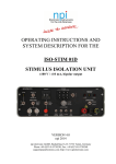
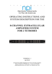
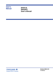
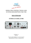
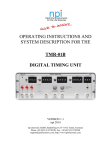
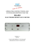
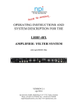
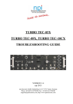
OPERATING INSTRUCTIONS AND
SYSTEM DESCRIPTION FOR THE
EXT-02 B
EXTRACELLULAR AMPLIFIER
VERSION 1.3
npi 2014
npi electronic GmbH, Bauhofring 16, D-71732 Tamm, Germany
Phone +49 (0)7141-9730230; Fax: +49 (0)7141-9730240
[email protected]; http://www.npielectronic.com
EXT-02 B User Manual
_______________________________________________________________________________________________________________
Table of Contents
1. Safety Regulations .............................................................................................................. 3
2. EXT-02 B ............................................................................................................................ 4
2.1. Components ................................................................................................................. 4
2.2. System Description ...................................................................................................... 4
2.3. Description of the Front Panel ..................................................................................... 4
2.4. Description of the Rear Panel ...................................................................................... 8
2.5. Headstage..................................................................................................................... 10
Headstage Elements ..................................................................................................... 10
3. Operation ............................................................................................................................ 10
3.1. Switching between recording and stimulation ............................................................. 10
3.2. Extracellular Recordings – Single-ended vs. differential ............................................ 11
3.3. System Bus – interconnecting devices......................................................................... 11
4. Technical Data .................................................................................................................... 14
___________________________________________________________________________
version 1.3
page 2
EXT-02 B User Manual
_______________________________________________________________________________________________________________
1. Safety Regulations
VERY IMPORTANT: Instruments and components supplied by npi electronic are NOT
intended for clinical use or medical purposes (e.g. for diagnosis or treatment of humans),
or for any other life-supporting system. npi electronic disclaims any warranties for such
purpose. Equipment supplied by npi electronic must be operated only by selected,
trained and adequately instructed personnel. For details please consult the GENERAL
TERMS OF DELIVERY AND CONDITIONS OF BUSINESS of npi electronic, D-71732
Tamm, Germany.
1)
GENERAL: This system is designed for use in scientific laboratories and must be
operated by trained staff only. General safety regulations for operating electrical devices
should be followed.
2)
AC MAINS CONNECTION: While working with the npi systems, always adhere to the
appropriate safety measures for handling electronic devices. Before using any device
please read manuals and instructions carefully.
The device is to be operated only at 115/230 Volt 60/50 Hz AC. Please check for
appropriate line voltage before connecting any system to mains.
Always use a three-wire line cord and a mains power-plug with a protection contact
connected to ground (protective earth).
Before opening the cabinet, unplug the instrument.
Unplug the instrument when replacing the fuse or changing line voltage. Replace fuse
only with an appropriate specified type.
3)
STATIC ELECTRICITY: Electronic equipment is sensitive to static discharges. Some
devices such as sensor inputs are equipped with very sensitive FET amplifiers, which can
be damaged by electrostatic charge and must therefore be handled with care. Electrostatic
discharge can be avoided by touching a grounded metal surface when changing or
adjusting sensors. Always turn power off when adding or removing modules,
connecting or disconnecting sensors, headstages or other components from the
instrument or 19” cabinet.
4)
TEMPERATURE DRIFT / WARM-UP TIME: All analog electronic systems are
sensitive to temperature changes. Therefore, all electronic instruments containing analog
circuits should be used only in a warmed-up condition (i.e. after internal temperature has
reached steady-state values). In most cases a warm-up period of 20-30 minutes is
sufficient.
5)
HANDLING: Please protect the device from moisture, heat, radiation and corrosive
chemicals.
___________________________________________________________________________
version 1.3
page 3
EXT-02 B User Manual
_______________________________________________________________________________________________________________
2. EXT-02 B
2.1.
Components
The following items are shipped with the EXT-02 B system:
✓
✓
✓
✓
✓
Amplifier (EXT-02 B)
User manual
Headstages
Power Supply
System Bus cable (slave configuration only)
2.2.
System Description
The EXT-02 B is designed for extracellular recordings of small voltage signals. It has a
switchable headstage, which enables the researcher to record and to stimulate through the
same electrode. The high-voltage signal for stimulation is fed into the amplifier via connectors
at the front panel, separately for each channel. Switching between recording and stimulation
can be done via a TTL signal or by manual switching.
The EXT-02 B has a differential input with high input impedance to avoid noise. The output
voltage signal can be HIGH PASS and LOW PASS filtered, and is available either AC (HIGH
PASS and LOW PASS filtered) with variable gain or DC coupled with a fixed gain of 10.
The EXT-02 B is built in a master configuration and a slave configuration. The master
configuration has got a built-in power supply and is capable of powering up to three EXT02 B in slave configuration. Furthermore, one audio monitor (AUD-08 B) and one electrode
resistance meter (REL-08 B). All these instruments are interconnected via the system bus,
which combines power and data lines.
2.3.
Description of the Front Panel
Figure 1: EXT-02 B front panel view
___________________________________________________________________________
version 1.3
page 4
EXT-02 B User Manual
_______________________________________________________________________________________________________________
In the following description of the front panel elements, each element has a number that is
related to that in Figure 1. The number is followed by the name (in uppercase letters) written
on the front panel and the type of the element (in lowercase letters). Then, a short description
of the element is given. Since the front panel elements are identical for each channel A and B
(with identical functions and labels) these elements are numbered and described only once (for
channel A). Signal is the recorded signal, REF is the signal from the reference input of the
headstage.
(1)
POWER LED
LED indicating that the EXT-02 B is powered on.
(2)
INPUT MODE switch
Rotary switch to select the input mode.
OFF:
both inputs of this channel (Signal + REF) are grounded
can be used to adjust the offset of the AC output
DIFF:
differential mode: signal is measured against REF.
SINGLE: single ended measurement: signal is measured against
GND
(3)
NOTCH switch
Switch that enables (upper position) or disables (lower position) the NOTCH filter.
Important: For correct resistance measurement with the REL-08B STIMULUS INPUT and
NOTCH filter have to be turned OFF!
(4)
HIGHPASS FILTER (Hz) switch
6-position switch for selecting the corner frequency of the single pole
HIGHPASS filter with -6 dB / octave.
Corner frequencies (Hz): 0.1, 1, 10, 30, 100, 300.
(5)
GAIN switch
4-position switch for selecting the GAIN of the output signal at the
AC OUTPUT connector (#10).
Amplification factors: x10, x100, x1k, x10k.
___________________________________________________________________________
version 1.3
page 5
EXT-02 B User Manual
_______________________________________________________________________________________________________________
(6)
LOWPASS FILTER (Hz) switch
6-position switch for selecting the corner frequency of the single pole
LOWPASS filter with -6 dB / octave.
Corner frequencies (Hz): 500, 1k, 3k, 5k, 10k, 20k.
(7)
OFFSET potentiometer
Potentiometer for OFFSET compensation for the measured potential at the
DC x10 OUTPUT (#9).
(8)
DC x10 OUTPUT
BNC connector providing the measured DC signal with a fixed amplification of
10. This signal is not filtered. Use of this connector allows, for instance,
measuring the signal AC (signal is provided at AC OUTPUT #9) while watching
the offset simultaneously.
(9)
AC OUTPUT connector
BNC connector providing the recorded and conditioned signal. The signal is
amplified by the factor set at #5 and filters with the corner frequencies set at #4 and
#6.
(10)
ZERO ADJ. trimpot
Trimpot for compensating for amplifier offsets. If the baseline is not zero even if the
input is grounded (INPUT MODE switch #3 set to OFF), this offset can be
compensated for.
Compensation procedure:
❏ Set the INPUT MODE switch (#2) to OFF to ground the inputs, and set the HIGH PASS
FILTER to 300 Hz.
❏ Set the GAIN range switch to 1k and adjust the baseline to zero using the trimpot.
❏ Set the GAIN range switch to 10k and adjust the baseline again if necessary.
___________________________________________________________________________
version 1.3
page 6
EXT-02 B User Manual
_______________________________________________________________________________________________________________
STIMULUS CONTROL section:
(11) TTL IN connector
BNC connector for a TTL input signal to switch the headstage from
recording mode (TTL = low) to stimulation mode (TTL = high).
(12) STIMULUS CONTROL switch
Toggle switch to switch the headstage from recording mode (OFF
position) to stimulation mode (ON position).
(13) STIMULUS INPUT connectors
2 mm banana jacks for connecting the high voltage signal for
stimulation. This input signal is fed to the headstage only if either the
TTL at #11 is high, or the switch #12 is in ON position.
Note: The stimulus ground (black connector) and the analog system ground are connected
internally.
Important: For correct resistance measurement with the REL-08B STIMULUS INPUT and
NOTCH filter have to be turned OFF!
(14)
HEADSTAGE connector
Connector for the standard sized headstage.
(15)
GROUND connector
Banana plug (4 mm) providing ground. The plug is connected internally to the
shields of the BNC connectors.
___________________________________________________________________________
version 1.3
page 7
EXT-02 B User Manual
_______________________________________________________________________________________________________________
2.4.
Description of the Rear Panel
Figure 2: EXT-02 B rear panel view
Since the rear panel elements for the two channel EXT-02B are identical for each channel A
and B (with identical functions and labels) these elements are numbered and described only
once (for channel B).
MONITORING section
(1) GAIN +1V…+4V connector
BNC connector providing a voltage monitoring the position of the GAIN of the AC
OUTPUT (+1 V to +4 V, 1 V/STEP).
(2) LOWPASS +1V…+6V connector
BNC connector providing a voltage monitoring the position of the LOWPASS FILTER
switch (+1 V to +6 V, 1 V/STEP).
(4) HIGHPASS +1V…+6V connector
BNC connector providing a voltage monitoring the position of the HIGHPASS FILTER
switch (+1 V to +6 V, 1 V/STEP).
(3) CHANNEL ADDRESS rotary switch (only in slave configuration)
Switch for selecting the address in the system bus, to which the recording channel will be
linked. This switch is only functional in amplifiers with slave configuration. Master amplifiers
will always have the addresses 0 (channel A) and 1 (channel B).
Important: Each recording channel has to have its dedicated address, i.e. no more than one
channel is allowed on a single address number. Otherwise incorrect output signals might occur
or the system might even be damaged.
___________________________________________________________________________
version 1.3
page 8
EXT-02 B User Manual
_______________________________________________________________________________________________________________
(5) SYSTEM BUS connector (see also chapter 3.3)
50-pin connecter providing power lines and data lines for connection of three EXT-02 B in
slave configuration to one EXT-02 B in master configuration. An electrode resistance meter
(REL-08 B) and an audio monitor (AUD-08 B) can also be connected via this system bus.
(6) POWER ON/OFF switch (only in master configuration)
Switch to power the EXT-02 B amplifier.
(7) POWER SUPPLY connector (only in master configuration)
Connector for an external power supply (18 V AC, min. 1.5 A).
Important: If you encounter noise when operating the EXT-02 B try to place the amplifier as
far away as possible from the power supply!! This will avoid magnetic coupling of the power
supply to the amplifier!
___________________________________________________________________________
version 1.3
page 9
EXT-02 B User Manual
_______________________________________________________________________________________________________________
2.5.
Headstage
Figure 3: headstage and electrode holder (optional) and of the EXT-02 B
Headstage Elements
1
2
3
4
BNC connector for the electrode holder (measuring electrode)
REF: SMC connector for the reference electrode
GND: Ground connector
holding bar
On request, PEL can be implemented using 1 mm or 2 mm banana jacks or using SMC
connectors.
Very Important: EXT-02 B headstage are always labeled “EXT-02 B” (see Figure 3) and must
not be exchanged with headstages from other npi electronic EXT amplifiers, e.g. the modular
(EXT-10 2F or EXT-10C) or desktop (EXT-02F) which are labeled “EXT” or “EXT-02”!
3. Operation
3.1. Switching between recording and stimulation
The EXT-02 B has a headstage which can be switched from recording mode to stimulation
mode. This enables the researcher to record and to stimulate through the same electrode.
Switching between recording and stimulation mode is achieved either by a TTL signal fed into
TTL IN connector (#11, Figure 1) or by manually toggling a switch (#12, Figure 1).
In recording mode, the signal detected at the electrode is pre-amplified in the headstage and
fed into the EXT-02 B for further amplification and filtering. In stimulation mode the
preamplifier in the headstage is disconnected from the electrode and the stimulation line is
connected to the electrode instead. The signal is fed into the stimulation line at the black and
red input connectors at the front panel (see #13, Figure 1).
___________________________________________________________________________
version 1.3
page 10
EXT-02 B User Manual
_______________________________________________________________________________________________________________
3.2.
Extracellular Recordings – Single-ended vs. differential
Extracellular measurements are mostly done in slices or in vivo, where distortions of the
signal caused by other instruments and the animal itself are very common. Additionally,
extracellular signals are very small and have to be amplified enormously. The drawback is that
noise is amplified as well. Therefore, each channel of the EXT-02 B is equipped with
differential input that minimizes noise pick-up. Differential means that the signal for the
amplifier is the difference between the positive (+) (PEL at the headstage) and negative (-)
(REF. at the headstage) input of the amplifier. This results in canceling of all signals which
both electrodes record, e.g. noise.
For differential measurements, both inputs are connected to electrodes using cables with
grounded enclosure or electrode holders. + (PEL) is connected to the measuring electrode and –
(REF.) to the reference electrode. The experimental chamber is grounded by an Ag-AgCl
pellet (or an AGAR bridge) connected to GND of the headstage (see Figure 4).
Important: If differential measurement is not required (single-ended measurement
configuration), the REF input must be connected to ground (GND at the headstage, see Figure
4) or the INPUT MODE switch (#2, Figure 1) must be set to SINGLE.
The amplifier is in an undefined state, if the REF is left open, and can go into saturation
making reliable measurements impossible.
3.3.
System Bus – interconnecting devices
Connecting multiple devices
The System Bus interconnects all amplifiers (EXT-02 B in master and slave configuration)
and monitoring devices (REL-08 B, AUD-08 B). It provides both power lines and all signal
lines. The number of signal lines depends on the number of connected amplifiers.
All devices of the B-series (EXT-02 B, REL-08 B, AUD-08 B) have two SYSTEM BUS
connectors at the rear panel (#5, Figure 2). To interconnect two or more devices, simply use
the provided cable and plug it into one of the SYTEM BUS connectors of each device.
This will result in a chain of devices, which has a maximum length of six (1 x EXT-02 B
master, 3 x EXT-02 B slave, 1 x AUD-08 B, 1 x REL-08 B). The order in which the devices
are chained up is not important. Since it is a bus system, all positions are treated equally.
Channel addresses
When using monitoring devices (REL-08 B, AUD-08 B) it is important, that each recording
channel has its dedicated address, i.e. that there is no more than one channel on a single
address number. This can be achieved by selecting a channel’s address number with the
CHANNEL ADDRESS rotary switch (#3, Figure 2) on the rear panel of the EXT-02 B in
slave configuration.
The EXT-02 B in master configuration does not have a CHANNEL ADDRESS rotary switch.
Its recording channels will always addressed to 0 for channel A and 1 for channel B. Therefore
the selectable addresses for the EXT-02 B in slave configuration begin at 2 and go up to 7.
Each recording channel can be monitored either acoustically with the AUD-08 B or its
electrode resistance can be measured with the REL-08 B. These devices have a CHANNEL
SELECT rotary switch on their front panel, whose numbers correspond to the channel address
number selected at each channel of the EXT-02 B.
___________________________________________________________________________
version 1.3
page 11
EXT-02 B User Manual
_______________________________________________________________________________________________________________
Figure 4: headstage connections, A: differential measurement, B: single-ended measurement
Hint: The REF connector of the headstage can also be set to GND by setting the INPUT
MODE switch (#2, Figure 1) to SINGLE.
❏
___________________________________________________________________________
version 1.3
page 12
EXT-02 B User Manual
_______________________________________________________________________________________________________________
4. Troubleshooting / FAQ
Issue
Reason
50 Hz noise
Magnetic field generated by Place power supply as distant as possible
power supply.
50 Hz noise
Solution
from the amplifier.
Undervoltage in power supply If the power supply has adjustable voltage,
generates ripples in supply make sure it is set to the right values. Make
voltage of the amplifier.
also sure that the power supply is capable of
providing enough current. Best: use the
provided power supply.
___________________________________________________________________________
version 1.3
page 13
EXT-02 B User Manual
_______________________________________________________________________________________________________________
5. Technical Data
Input (headstage):
>1012 Ω, range ±1 V
Differential Input:
CMR >90 dB at 1 kHz (tested with 0 Ω input resistance)
Input Capacitance:
30 pF
OFFSET compensation: set by potentiometer, range: ±1 V
NOTCH Filter:
50 Hz (Europe) / 60 Hz (USA)
HIGHPASS Filter:
single pole, attenuation: -6 dB / octave,
corner frequencies (Hz): 0.1, 1, 10, 30, 100, 300
LOWPASS Filter:
single pole, attenuation: -6 dB/octave,
corner frequencies (Hz): 500, 1k, 3k, 5k, 10k, 20k
GAIN:
rotary-switch 10-100-1k-10k
Output:
range: ±10 V into 1 kΩ / ±1 V into 50 Ω
Power Supply:
18V, AC, min. 1.8 A
Dimensions:
305 x 180 x 105 mm3 (W x D x H)
Headstage
Input (headstage):
>1012 Ω, range ±1 V
Headstage Size:
70 x 26 x 26 mm3
Holding Bar:
length: 150 mm; diameter: 8 mm
___________________________________________________________________________
version 1.3
page 14