1
NOTES
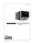
DPC535 Quick Start Operating
Instructions
DIFFERENTIAL PRESSURE CONTROL USING STRAIN
GAGE TRANSDUCERS
Refer to the full manual for unpacking and mounting instructions and terminal
locations.
When using the DPC535 as a differential pressure controller (DPC535-1-1-1-2-K) with
350 Ohm Strain Gage pressure transducers such as the Dynisco PT460 series, wire as
follows:
NOTE: Transducers must be of the same range.
For PV1 (upstream):
Connect positive signal wire (red) to terminal 32.
Connect negative signal wire (black) to terminal 31.
Connect Excitation - (green) to terminal 10.
Connect Excitation + (white) to terminal 11.
Connect Calibration 1 (blue) to terminal 10.
Connect Calibration 2 (orange) to terminal 12.
For PV2 (downstream):
Connect positive signal wire (red) to terminal 29.
Connect the negative signal wire (black) to terminal 28.
Connect Excitation - (green) to terminal 10.
Connect Excitation + (white) to terminal 11.
Connect Calibration 1 (blue) to terminal 10.
Connect Calibration 2 (orange) to terminal 22.
Refer to the full manual for instructions on accessing the following menus:
IN THE CONFIGURATION MENU:
Set CTR.TYPE to Standard, Set LINE.FREQ to 60, Set PV SOURCE to PV1-PV2, Set
OUTPUT 2 to ALARM ON, Set OUTPUT 3 to ALARM ON, Set OUTPUT 4 to
RETRANS. Set ANLG.RNG.: 4 to desired output (4-20, 0-20, 20-4, 20-0mA), Define
LOOP NAME if desired.
IN THE PV1 MENU:
Set PV1 TYPE to 0-33.3 mV, Set LOW RANGE to match low range of transducer, Set
HI RANGE to match the full-scale range of transducers, Set RESTORE to manual.
IN THE PV2 MENU:
Set PV2SETUP to same as PV1.
IN THE CONTROL MENU:
Set ALGORITHM to On/Off, Set SOURCE to PV (differential), Set ACTION to
DIRECT, Set PVBREAK to Off.
IN THE ALARM 1 AND 2 MENUS:
Set TYPE, SOURCE and MODE (latching or non-latching) as appropriate to the
process. Set Alarm 1 OUTPUT to 2. This will cause its output to be at the output
2 terminals. Set Alarm 2 OUTPUT to 3. This will cause its output to be at the
output 3 terminals. Set POWER UP as desired. If set to normal, the process will
be powered up in the normal mode. If there is an alarm condition, the alarm will
be activated. If set to ALARM, alarms will be activated on power up. If set to
delayed, alarms will be inhibited regardless of whether or not an alarm condition
exists. Define MESSAGE if desired.
IN THE RETRANS MENU:
Set the TYP:4 To PV (differential), Set LO RANGE: 4 to the desired low end of
the range, Set HI RANGE: 4 to the desired high end of the range. Under most
conditions, LO RANGE and HI RANGE will encompass the full span setting of
the PV’s.
IN THE SPECIAL MENU:
Set the POWER UP to Manual.