1
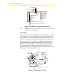
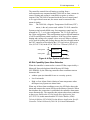
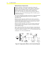
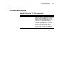
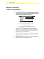
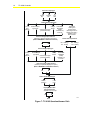
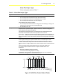
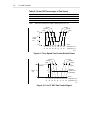
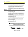
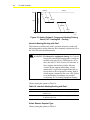
FANs 637.5, 1637.5 TC-9100 Controller Section Issue Date 0400 APPLICATION NOTE TC-9102 Applications Configuring TC-9102 Applications ......................................................3 Introduction......................................................................................................... 3 Key Concepts...................................................................................................... 4 TC-9102 Controller ......................................................................................................... 4 Control Modes ............................................................................................................... *8 Procedure Overview ......................................................................................... 13 Detailed Procedures ......................................................................................... 14 Creating a New Configuration ...................................................................................... *14 Troubleshooting ..............................................................................................*24 Attributes and Parameters ............................................................................... 25 Fan Coil I/O Points........................................................................................................ 25 Fan Coil Parameters..................................................................................................... 26 *Indicates those sections where changes have occurred since the last printing. © 2000 Johnson Controls, Inc. Code No. LIT-6375130 www.johnsoncontrols.com 2 TC-9100 Controller TC-9102 Applications Configuring TC-9102 Applications Introduction This section provides an overview of the TC-9102 controller applications and their configuration. This application note describes how to create a new configuration. 3 4 TC-9100 Controller Key Concepts TC-9102 Controller Overview The TC-9102 controller is preconfigured for fan coil application. The user cannot modify the sequence. The user selects the types of fan control, heating and cooling valve control, and remote setpoint. The heating and/or cooling valve control types must be the same for both outputs. The TC-9102 modulates or cycles the heating and cooling valves to control space temperature. The fan speed also modulates or cycles to control space temperature. For specifications, technical data, actuator, and ordering information, refer to the TC-9102 Terminal Controller Technical Bulletin (LIT-6363050) in the Metasys Application Specific Controllers Technical Manual (FAN 636.3). Configure the TC-9102 controller using HVAC PRO (Figure 1). File Open New Select Existing File Terminal Unit Applications TC Fan Coil tccflw Figure 1: TC-9102 Application Configuration Paths Terminology European terminology is used throughout this document. Table 1 provides the equivalent European and North American modes. Table 2 defines some terms used in this manual. TC-9102 Applications 5 Table 1: European and North American Terminology European North American Comfort Occupied Comfort Setpoint Cooling Occupied Cooling Setpoint Comfort Setpoint Heating Occupied Heating Setpoint Earth Earth Ground N2 COM N2 REF Night * Unoccupied Night Cooling Setpoint Bias * Unoccupied Cooling Setpoint Bias Night Heating Setpoint Bias * Unoccupied Heating Setpoint Bias Off Shutdown Standby Economy or Temporarily Unoccupied ** Standby Cooling Setpoint Bias Economy Cooling Setpoint Bias ** Standby Heating Setpoint Bias Economy Heating Setpoint Bias ** Winter/Summer Compensation Compensation * Not available for TC-9102 in Standalone mode; use Standby mode. ** Provides intermediate setpoints for energy savings. Table 2: Terminology Definitions Term Definition 0 to 10 VDC Proportional DAT Duration Adjust Type PAT Position Adjust Type (Incremental) PWM Pulse Width Modulated (Europe only) WSP Working Setpoints WSP Cooling Working Setpoint Cooling WSP Heating Working Setpoint Heating Software Configuration Numbers Figure 2 provides a guide for determining the type of controller, based on the configuration number assigned to it. For example, a software configuration of TC-9102-0667 is a controller with two heat stages, two cooling stages, a 3-speed fan, and +/-5 setpoint. 6 TC-9100 Controller TC-910A-0BCD 2 = Fan Coil Heating Type Cooling Type Fan and Setpoint Type 0 = 0-10V 55/85 1 = on-off 55/85 2 = 3 spd 55/85 3 = (not used) 4 = (not used) 5 = 0-10V +/- 5 6 = on-off +/- 5 7 = 3 spd +/- 5 1 = PMW (European) 2 = 0-10V 3 = (not used) 4 = DAT 5 = PAT 6 = 2 stage A = Sequenced htg and clg Direct Acting B = Sequenced htg and clg Reverse Acting cinf Figure 2: Software Configuration Numbers Note: Refer to the TC-9102 Terminal Controller Technical Bulletin for hardware configuration. Description A fan coil unit controls the temperature of an individual space. Often used in entryways, motel and hospital rooms, and in perimeter zones, fan coil units have a fan, heating and/or cooling coil, and filter. The controller does not provide time-delay requirements for compressors. In some cases, the fan coil unit has a manually adjustable outside air damper for minimum ventilation requirements. If the unit has an automatic outside air damper, a hardwired fan interlock is required. Or, use either the unit ventilator or rooftop application in a UNT (Unitary Controller) as described in the UNT Controller section of the HVAC PRO User’s Manual (FAN 637.5). Wall or Ceiling Conditioned Air TM-9100 Room Command Module..... Unit Casing TC-9102 Controller Fan Heating and/or Cooling Coil Air Filter Return Air fancl Figure 3: Typical Fan Coil Unit TC-9102 Applications 7 The controller controls fan coil heating or cooling from a wall-mounted room command module (TM-9100) or from a return-air sensor. Heating and cooling is controlled in sequence to achieve setpoint. If the TM-9100 is mounted inside the fan coil control panel as in a typical hotel-room unit, the sensor must be mounted in the return-air intake. Note: The TM-9100, a Negative Temperature Coefficient (NTC) sensor, is the only sensor used with the TC-9102 controller. Systems using hot and chilled water for temperature control may be arranged in a 2-, 3-, or 4-pipe configuration. The TC-9102 applies to the 4-pipe configuration. This configuration requires different numbers of valves and different control sequences. If the fan coil has separate heating and cooling coils, separate valves are used. When a common coil is used for heating and cooling, then use the fan coil application in the UNT controller as described in the UNT Applications Application Note (LIT-6375100) in the HVAC PRO User’s Manual (FAN 637.5). Heating Valve Heating Coil 4-Pipe..... Cooling Valve Cooling Coil tccoils Figure 4: 4-Pipe System Application N2 Dial Capability Upon Alarm Detection When the controller is connected to a remote N2 Bus, supervised by a Metasys Network telephone-linked Metasys N2 Dialer (NU-NDM101-0), the following controller-alarm conditions start an automatic dial: • window open (not intended for use as a security system) • Low-Limit mode • High- or Low-Alarm Limit violation of room temperature when the Supervisory System sets alarm limits When any of these alarm conditions occurs, the N2 Dialer detects the alarm and connects the remote N2 Bus to the Metasys Network. When the telephone line connection is established, the controller alarm status resets automatically. The controller then reports other alarm conditions as they occur. Refer to the N2 Dial Application Application Note (LIT-6375150) in this manual and the N2 Dialer Module (NDM) Technical Bulletin (LIT-6363065) in the Metasys Application Specific Controller Technical Manual (FAN 636.3) for more information. 8 TC-9100 Controller Control Modes Standalone Mode The controller operates in Standalone mode when it is not connected to a Supervisory System via the N2 Bus. In Standalone mode, the controller operates in one of three Control modes: • Comfort (Occupied): Control at comfort setpoint • Standby (Temporarily Unoccupied): Control at a standby-level setpoint • Off (Shutdown): Low-limit temperature control only The window contact, occupancy sensor, and occupancy inputs set the Control mode and Alternate mode. The occupancy sensor is any device indicates the presence of people in a space. Occupancy sensors require appropriate time-out circuits to prevent mode cycling. The Occupancy button on the TM-9100 thermostat modifies the Control modes (Table 3). Pressing the Occupancy button toggles between the Control mode and the Alternate mode. Table 3: Standalone Modes Window Contact Occupancy Sensor * Control Mode Alternate Mode (Occupancy Button) Open Disabled Off Disabled Closed Closed Comfort Standby Open Standby Comfort * Status of occupancy in space (Closed = Occupied) Supervisory Mode When the controller connects to a Supervisory System via the N2 Bus, it operates in the following modes: • Comfort (Occupied): Control at comfort setpoint • Standby (Temporarily Unoccupied): Control at a standby level setpoint • Off (Shutdown): Low limit temperature control only • Night (Unoccupied): Control at a night level setpoint Night is the default control mode. If the window contact input is open, the controller stays in the Off Control mode, overriding any Supervisory mode or occupancy sensor. Refer to Table 4. TC-9102 Applications 9 The Supervisory System sets the Control modes. Changing the Supervisory mode overrides the Alternate mode. The occupancy sensor input and the TM-9100 Occupancy button modify the Control modes (Table 4). The window-contact input switches the controller to the Off Control mode. The TM-9100 Occupancy button switches the controller operation mode between Alternate mode and Control mode. The Timed-Comfort Alternate mode is active for one hour, non-adjustable, after which the controller returns to the normal Control mode. Table 4: Supervisory Modes Window Contact Supervisory Mode Occupancy Sensor * Control Mode Alternate Mode (Occupancy Button) Open Any Mode Disabled Off Disabled Closed Off Night Standby Comfort Closed Off Off Open Off Off Closed Night Timed Comfort Open Night Timed Comfort Closed Standby Comfort Open Standby Timed Comfort Closed Comfort Standby Open Standby Comfort * Status of occupancy in space (Closed = Occupied) 10 TC-9100 Controller Manual Modes When the controller connects to a Supervisory System via the N2 Bus, and that system is set to Manual mode, the controller operates in four modes. Refer to Table 5. The Manual mode, available from the Supervisory System, disables the occupancy sensor and Occupancy button functions. Table 5: Manual Modes Window Contact Manual Mode Occupancy Sensor Control Mode Alternate Mode (Occupancy Button) Open Any Mode Disabled Off Disabled Closed Off Disabled Off Disabled Night Disabled Night Disabled Standby Disabled Standby Disabled Comfort Disabled Comfort Disabled Controller Setpoints The setpoint in all Control modes may be modified by adjusting the remote setpoint dial on the TM-9100, or from the integrated setpoint adjuster (available only in Europe). The controller models without an integrated setpoint adjuster require that a TM-9100 or an external potentiometer is connected to adjust the setpoint. When a Supervisory System is connected, the setpoint can be further decreased or increased in the Standby and Night Control mode to further reduce energy requirements during scheduled, unoccupied periods such as nights, weekends, and holidays. The TC-9102 controller does not have a built-in realtime clock. The controller has two comfort setpoints: comfort setpoint heating and comfort setpoint cooling. The difference between these two values determines the zero energy band where neither heating nor cooling is required. The controller calculates two Working Setpoints (WSP): WSP heating and WSP cooling. The WSP heating and cooling are the sum of the occupied setpoint values, the remote setpoint value coming from the TM-9100, or the integrated setpoint adjuster (available only in Europe) and the common setpoint value. TC-9102 Applications 11 In the Supervisory mode, make working setpoint adjustments either by changing the comfort setpoints or by changing the value in the common setpoint parameter of the controller, which enables the Supervisory System operator to adjust the setpoints for heating and cooling at the same time without affecting the zero energy band. In summary: For the Heating Setpoint calculation, A = B+C+D+E+F, where: A = Working Setpoint (Heating) B = Comfort Setpoint (Heating) C = Remote Setpoint (integrated adjuster available only in Europe or TM-9100 dial) D = Common Setpoint (Supervisory System) E = Standby or Night Bias Heating (if mode is active) F = Winter Compensation (if enabled) For the Cooling Setpoint calculation, A = B+C+D+E+F, where: A = Working Setpoint (Cooling) B = Comfort Setpoint (Cooling) C = Remote Setpoint (integrated adjuster available only in Europe or TM-9100 dial) D = Common Setpoint (Supervisory System) E = Standby or Night Bias Cooling (if mode is active) F = Summer Compensation (if enabled) When the room temperature is below the Working Setpoint for heating, the heating output increases according to the proportional band and integral time parameters set for the heating control loop. When the room temperature is above the Working Setpoint for cooling, the cooling output increases according to the proportional band and integral time parameters set for the cooling control loop. Low-Limit Mode The Low-Limit mode is active when the room temperature falls below the low limit setpoint. The Low-Limit mode protects the space and its furnishings from low temperatures. The fan switches on at full speed, and the heating output is set to the maximum level until the room temperature rises by the low limit differential value. 12 TC-9100 Controller Winter/Summer Compensation When the controller is connected to a Supervisory System, the Compensation modes are available. Winter/Summer Compensation provides a natural setpoint deviation in response to outside air, to provide energy savings. These modes must be enabled using HVAC PRO. The Supervisory System must provide the outside air temperature value via the N2 Bus through a GPL/JC-BASIC process or Global Data Sharing. After a power interruption, the Winter and Summer Compensation modes are temporarily disabled until N2 Bus receives a new outdoor air temperature value. When the outdoor temperature falls below the winter setpoint, the Working Setpoint of the controller is raised or lowered in accordance with the winter authority slope as degrees compensation per degrees outside air temperature (degree per degree). When the outdoor temperature rises above the summer setpoint, the Working Setpoint of the controller is raised in accordance with the summer authority slope. Figure 5 shows the effect of the winter and summer compensation on the controller setpoint. The winter/summer authority slope is defined as degree per degree. Heating has a -3°C (-5°F) reset-default limit, and cooling has a 5°C (9°F) reset-default limit. Winter Authority Slope Winter Change Limit Summer Authority Slope Setpoint Compensation Summer Change Limit 4 10 16 21 27 32 (°C) 40 50 60 70 80 90 (°F) Winter Change Limit Winter Setpoint Defaults to 10°C (50°F) Summer Setpoint Defaults to 24°C (75°F) Outdoor Air Temperature winsumtc Figure 5: Compensation Effect on the Controller Setpoint TC-9102 Applications 13 Procedure Overview Table 6: Configuring TC-9102 Applications To Do This Follow These Steps: Create a New Configuration In the File menu, select New. Click on the arrow to the right of the Application Group field to display a list of available groups. Use the scroll bar on the side of the drop-down box to see the entire list. Click on Terminal Unit Applications. Double-click on TC Fan Coil to select a TC Fan Coil application. The Question/Answer session begins. Select options in the question/answer session based on the information provided in the Detailed Procedures section. 14 TC-9100 Controller Detailed Procedures Creating a New Configuration To create a new configuration: 1. In the File menu, select New. The File New/Application Selection dialog box displays all application groups and, once selected, the applications for the application group (Figure 6). File New / Application Selection Application Group: Terminal Unit Applications Applications: Unit Vent Fan Coil Heat Pump TC Fan Coil OK Cancel tcnew Figure 6: TC-9102 Application Selection Dialog Box 2. Click on the arrow to the right of the Application Group field to display a list of available groups. Use the scroll bar on the side of the drop-down box to see the entire list. 3. Click on Terminal Unit Applications. HVAC PRO automatically displays the list of available applications for the Terminal Unit Applications group. 4. Double-click on TC Fan Coil to select a TC Fan Coil application. The Question/Answer session begins (Figure 7). TC-9102 Applications 5. 15 Select options in the question/answer session based on the information that follows. ! WARNING: Fire hazard or equipment damage. For 3-speed fan models, interlocked heating and/or cooling are enabled using only HVAC PRO Release 6.03 or later, and only TC-9102 Version 3.0 firmware, or later, supports interlocking. Earlier firmware versions do not support interlocking. Always interlock the 3-speed fan in applications such as electric heat or direct-expansion cooling, both of which require constant air flow over coils. Failure to set interlocking accordingly may result in overheating, fire, or cooling-equipment damage. 16 TC-9100 Controller Select fan output type: On/Off Fan 3-speed Fan 0-10 VDC Select heating output type: 0 to 10 VDC (PROP) Duration Adjust Type (DAT) Position Adjust Type (PAT/Incremental) 2 Stage On/Off Pulse Width Modulated (PWM) Available only in Europe. Interlock heating output with fan? (Selecting 3-speed fan displays this option.) (Refer to WARNING in Detailed Procedures.) Yes Sequenced Heating and Cooling Valves (Selecting on/off fan displays this option.) Available only in North America. Select valve fail positions: NO - Heating / NC - Cooling No NC - Heating / NO - Cooling Select cooling output type: 0 to 10 VDC (PROP) Duration Adjust Type (DAT) Position Adjust Type (PAT/Incremental) 2 Stage On/Off Pulse Width Modulated (PWM) Available only in Europe. Interlock cooling output with fan? (Selecting 3-speed fan displays this option.) (Refer to WARNING in Detailed Procedures.) Yes No Select remote setpoint type: 55/85°F (12/28°C) +/- 5°F (3°C) Display module with unit-mounted NTC? Available only in Europe. Yes No Done Figure 7: TC-9102 Question/Answer Path tctree TC-9102 Applications 17 Select Fan Output Type Choose among the options in Table 7. Table 7: Select Fan Output Type Option Description On/Off Fan The On/Off fan control (Figure 8) output is on when: • the room temperature is below the Working Setpoint for heating • the room temperature is above the Working Setpoint for cooling • the room temperature falls below the low limit setpoint The On/Off fan control output is off when: • the room temperature reaches the zero-energy band, when heating or cooling is not required, by the value set for the fan On/Off differential • the controller is set to Off 3-Speed Fan The fan stages automatically switch in sequence with increasing or decreasing room temperature for 3-speed fan outputs. Speed 1 remains on, in the zero-energy band, around setpoint. See Table 8 and Figure 9. The speed of a 3-speed fan may be set manually from the TM-9100 wall mounted thermostat. The TM-9100 selector switch Off position turns the fan off. In the auto “A” position, the controller sets the speed according to room temperature. In the “1,” “2,” or “3” positions, the fan runs at the selected speed. With TC-9102 firmware Version 3.0 and later, the TM-9100 selector switch is inactive during Night and Standby modes. 0 to 10 VDC A 0-to-10 VDC output from the controller controls fan speed (Figure 10). The output is a control signal for driving a fan speed controller with a 0 to 10 VDC input. The fan controller provides opto-isolation. As the output voltage increases, the fan speed controller must increase fan speed from fan motor minimum to maximum. When the output is below the voltage required from the minimum speed, the fan must be switched off. The fan runs continuously in the Comfort mode on 0 to 10 VDC models. The 0 to 10 VDC output increases to drive the fan speed controller as the room temperature: • falls below the Working Setpoint for heating • or rises above the Working Setpoint for cooling It maintains a minimum output, set by default at 50%, when the room temperature enters the zero energy band. In Off mode, the fan is off. Low Limit Night Comfort Night Standby Standby 12 54 16 60 On Off 14 58 18 64 20 68 22 72 24 76 26 80 Room .....(°C) Temperature Temperature .....(°F) tcswitch Figure 8: On/Off Fan Control Switch Points TC-9100 Controller Table 8: On and Off Percentages of Fan Speed Heat/Cool On Heat/Cool Off 1 Controller Fan Speed 30 20 2 60 50 3 90 80 Note: Define the minimum fan output to allow the fan to turn off. 90 Comfort Standby Night 60 Control Output Fan 30 Comfort Standby Night Low Limit 0% Room 12 14 16 54 58 60 18 64 20 68 22 24 26 Temperature (°C) 72 76 80 Temperature (°F) 3speed Figure 9: Three Speed Fan Control Switch Points Comfort Standby Night 100 Output (%) Comfort Standby Night Cooling Heating Low Limit 18 50 Minimum Speed Level ..... (adjustable)..... 0 Room 12 54 14 58 16 18 20 22 60 64 68 72 24 76 26 80 Temperature (°C) Temperature (°F) vdctc Figure 10: 0 to 10 VDC Fan Control Signal TC-9102 Applications 19 Select Heating and Cooling Output Types All heating and cooling output types can be interlocked to 3-speed fan operation. When Interlock functions are selected, the outputs are off when the fan is off. Refer to Interlock Heating/Cooling with Fan? in this section. Choose among the options in Table 9. Table 9: Select Heating and Cooling Output Types Option Description 0 to 10 VDC (PROP) The output is an analog voltage that varies between 0 and 10 VDC in direct proportion to the controller output from 0 to 100%. The heating/cooling output indicates the output level in heating or cooling, depending on the actual room temperature compared with the Working Setpoints. The Data Definition Language (DDL) generated shows only OCM1 for this output and should be monitored as the heating/cooling control output. While in the Heating mode, an override to the heating/cooling output only affects the heating output. While in the Cooling mode, an override only affects the cooling output. Analog output ranges are fixed at 0 to 10 VDC for 0 to 100% command and cannot be rescaled. Duration Adjust Type (DAT) The Duration Adjust Type (DAT) output is a triac switched on for a duration within the set heating and/or cooling valve cycle in direct proportion to the controller output from 0 to 100% (Figure 11). To avoid unnecessary switching of the valve actuator: • the triac remains off when the output is between 0 and 5% • the triac remains on when the output is between 95 and 100% The cycle time is defaulted to 300 seconds. Position Adjust Type (PAT/Incremental) The Position Adjust Type (PAT) output is a pair of triacs switched on to open or close an incrementally driven heating and/or cooling valve (Figure 12). The duration of the pulse is based on the change in percent command multiplied by the full stroke time of the actuator. A 100% change will completely open or close the valve. At the 0% or 100% position, the duration of switching increases to ensure that the valve is completely at its end position. Also, the appropriate triac is switched on every two hours for the full stroke time to ensure that the valve remains at its end position. To prevent unnecessary wear on the actuator, the triac output only switches when either: • the output change exceeds 1% in the same direction as the previous change • or, the output change exceeds 2% if the direction of change reverses The full stroke time is defaulted to 60 seconds. Two Stage On/Off The two stage on/off output is a pair of triacs switched on in sequence as the controller output increases. 1. The first stage triac switches on when the output exceeds 0%. 2. The second stage triac switches on when the output is equal to the configured load rating, which defaults to 50%. The switching differential is fixed at 5% (Figure 13). Continued on next page . . . 20 TC-9100 Controller Option (Cont.) Description Pulse Width Modulated (PWM) This feature is available only in Europe. The output is a high frequency Pulse Width Modulated (PWM) control signal where the width of the pulse varies from 0 to 100% as a controller output function. The heating/cooling output indicates the output level in heating or cooling, depending on the actual room temperature compared with the Working Setpoints. The DDL generated shows only OCM1 for this output and should be monitored as the heating/cooling control output. While in the heating mode, an override to the heating/cooling output only affects the heating output. While in the cooling mode, an override only affects the cooling output. Sequenced Heating and Cooling Valves This feature is available only with On/Off Fan selected. Select this function if the system is so equipped. Select Valve Fail Positions This feature, available only with Sequenced Heating and Cooling Valves selected, sets the default valve-fail positions for sequenced valves. Figure 14 and Figure 15 show the valve functions for each fail position. NO - Heating/NC - Cooling The output is an analog voltage that varies between 0 and 10 VDC in direct proportion to the controller output from 0 to 100% (Figure 14). The heating and cooling output modulates from 5 to 0 VDC as the space temperature drops below the heating Working Setpoint and modulates from 5 to 10 VDC as the space temperature rises above the cooling Working Setpoint. The Data Definition Language (DDL) generated shows the common output OCM5 for this output and should be monitored as the heating/cooling control output. At 50%, both heating and cooling are off. NC - Heating/NO - Cooling The output is an analog voltage that varies between 0 and 10 VDC in direct proportion to the controller output from 0 to 100% (Figure 15). The heating and cooling output modulates from 5 to 10 VDC as the space temperature drops below the heating Working Setpoint and modulates from 5 to 0 VDC as the space temperature rises above the cooling Working Setpoint. The Data Definition Language (DDL) generated shows the common output OCM5 for this output and should be monitored as the heating/cooling control output. At 50%, both heating and cooling are off. ! CAUTION: Equipment damage. Mechanical equipment using compressors must be equipped with minimum runtime delay relays. On Off 50% Output DAT Cycle Time 30% Output DAT Cycle Time dat Figure 11: DAT Output 21 TC-9102 Applications Comfort Standby Night Heating Cooling Low Limit 100 Comfort Standby Night Output (%) Room 0 12 54 14 58 16 60 18 64 20 68 22 72 .....(°C) Temperature Temperature .....(°F) 26 80 24 76 0to10 Figure 12: Heating and Cooling Control 0 to 10 VDC, DAT, PAT, and PWM Comfort Standby Night Heating Cooling Low Limit 100 Comfort Standby Night Output (%) 2 2 1 0 12 54 14 58 16 60 2 1 18 64 2 2 11 20 68 22 72 2 1 1 Room 24 76 26 80 Temperature (°F) Temperature (°C) 2stage Figure 13: Heating and Cooling Control, Two Stage On/Off Heating 100% Cooling Night 50% Low Limit Standby Comfort Standby 0% Night Low Limit 60 64 68 72 76 80 Room Temperature noheat Figure 14: Analog Output 2, Sequenced Heating/Cooling Valves, NO - Heating/NC - Cooling TC-9100 Controller Heating 100% Cooling Night Standby 50% Low Limit 22 Comfort Standby Night 0% Low Limit 60 64 68 72 76 80 Room Temperature ncheat Figure 15: Analog Output 2, Sequenced Heating/Cooling Valves, NC - Heating/NO - Cooling Interlock Heating/Cooling with Fan? This function, available only with 3-speed fan selected, switches off the heating and/or cooling when the fan is manually switched to Off at the TM-9100 wall-mount thermostat. ! WARNING: Fire hazard or equipment damage. For 3-speed fan models, interlocked heating and/or cooling are enabled using only HVAC PRO Release 6.03 or later, and only TC-9102 Version 3.0 firmware, or later, supports interlocking. Earlier firmware versions do not support interlocking. Always interlock the 3-speed fan in applications such as electric heat or direct-expansion cooling, both of which require constant air flow over coils. Failure to set interlocking accordingly may result in overheating, fire, or cooling-equipment damage. Choose among the options in Table 10. Table 10: Interlock Heating/Cooling with Fan? Option Description Yes This option turns off the heating and cooling outputs when the fan is off. No This option allows the heating and cooling outputs to remain on when the fan is off. Select Remote Setpoint Type Choose among the options in Table 11. TC-9102 Applications 23 Table 11: Select Remote Setpoint Type Option Description 12 to 28°°C (55 to 85°°F) This selection sets the controller parameters to allow the integrated setpoint adjuster (available only in Europe) or TM-9100 remote setpoint dial to adjust the controller setpoint up and down. Read and learn the Controller Setpoints topic in the Key Concepts section of this technical bulletin for an explanation of how the Working Setpoint is calculated. -/+ 3°°C (5°°F) This selection sets the controller parameters to allow the integrated setpoint adjuster (available only in Europe) or TM-9100 remote setpoint dial to adjust the setpoint up and down from the current setpoint loaded into the controller. Read and learn the Controller Setpoints topic in the Key Concepts section of this technical bulletin for an explanation of how the Working Setpoint is calculated. Display Module with Unit Mounted NTC? Note: This feature is available only in Europe. Choose among the options in Table 12. Table 12: Display Module with Unit Mounted NTC? Option Description Yes Select this option when the controller has a TM-9180 Display Module but a locally wired, unit-mounted NTC sensor reads the temperature. No Select this option when the controller has a TM-9180 Display Module and the display module reads the temperature, or when a TM-9100 series thermostat is connected, or if only a unit-mounted sensor is used without a TM-9100. 24 TC-9100 Controller Troubleshooting The following concerns a problem that may occur when changing the Night Bias Heating parameter. Table 13: Troubleshooting TC-9102 Controllers Error/Condition Problem Solution Change in Night Bias Heating Parameter Causes Heating Output to Remain On Changing the TC-9102 controller Night Bias Heating parameter from its default value may cause the heating output to remain on when the fan is off. In electric heat applications, air flow is required to avoid overheating. This condition affects all TC-9102 controllers using HVAC PRO prior to Release 6.04. Ensure that the Night Bias Heating default value remains set to -4°C (-8.00°F) on all TC-9102 controllers. HVAC PRO Release 6.04 eliminates this condition for all Night Bias Heating parameter values. TC-9102 Applications 25 Attributes and Parameters Fan Coil I/O Points The TC-9102 fan coil input and output point types, indexes, names, and descriptions are described below (Table 14). Note: Table 14 and Table 15 should assign possibilities depending on configuration during the Question and Answer session. Table 14: TC-9102 Fan Coil Default Point Assignments Type Analog Inputs Binary Inputs Analog Outputs Binary Outputs Number Longname AI 1 Room Temp AI 2 Remote Setpoint AI 2 Warmer Cooler Adjust AI 4 Override Input BI 1 Window Contact BI 2 Occupancy Sensor AO 1 Htg/Clg Output AO 1 Htg/Clg Output PWM AO 3 Control Output Fan BO 1 Heating DAT BO 1 Htg Vlv PAT Open BO 1 Heating Stage 1 BO 2 Fan BO 2 Htg Vlv PAT Close BO 2 Heating Stage 2 BO 3 Heating DAT BO 3 Htg Vlv PAT Open BO 3 Heating Stage 1 BO 3 Cooling DAT BO 3 Clg Vlv PAT Open BO 3 Cooling Stage 1 BO 4 Htg Vlv PAT Close BO 4 Heating Stage 2 BO 4 Clg Vlv PAT Close BO 4 Cooling Stage 2 BO 5 Fan (Speed 1) BO 5 Cooling DAT BO 5 Clg Vlv PAT Open BO 5 Cooling Stage 1 BO 6 Fan (Speed 2) BO 6 Clg Vlv PAT Close BO 6 Cooling Stage 2 BO 7 Fan (Speed 3) 26 TC-9100 Controller Fan Coil Parameters The TC-9102 fan coil parameter point locations, default values, and descriptions are outlined below (Table 15). Table 15: TC-9102 Fan Coil Default Parameter Assignment and Related Features Longname Hardware Reference Default Value Description Supv. Requested Mode MODC 0 = Night Supervisory Mode 0 = Night, 1 = Standby 2 = Comfort 3 = Off Supv. Manual Mode MAN 0 = Off Supervisory Manual Mode (locks out mode button) Operating Status MODS 0 = Night Mode 0 = Night 1 = Standby 2 = Comfort 3 = Off Alternate Mode MODA 0 = Off Mode button from TM-9100 active Low Limit Mode AFM 0 = Off Low Limit mode Low Limit Setpoint xxxx 12.0°C (54.0°F) Low Limit setpoint Low Limit Differential xxxx 2.0°C (4.0°F) Low Limit differential Winter Compensation xxxx 0 = Off Winter compensation Winter Setpoint xxxx 10.0°C (50.0°F) Winter compensation setpoint Winter Authority Slope xxxx -0.1 Deg/Deg Winter compensation authority slope Winter Comp Limit xxxx -3.0 Deg. C (-5.0 Deg. F) Winter compensation limit Note: This is a Revision 3 (or greater) firmware feature. Controller shows values as unreliable if commissioning Revision 2 or earlier. Winter WSP Compensation WAC Calculated Winter compensation Working Setpoint Summer Compensation xxxx 0 = Disabled Summer compensation Summer Setpoint xxxx 24.0°C (75.0°F) Summer compensation setpoint Summer Authority Slope xxxx 0.2 Deg/Deg Summer compensation authority slope Summer Comp Limit xxxx 5.0 Deg. C (9.0 Deg. F) Summer compensation limit Note: This is a Revision 3 (or greater) firmware feature. Controller shows values as unreliable if commissioning Revision 2 or earlier. Summer WSP Compensation SAC Calculated Summer compensation Working Setpoint Continued on next page . . . TC-9102 Applications Longname (Cont.) Hardware Reference Default Value Description Common Setpoint PM6K1 0.0°C (0.0°F) Common setpoint for Supervisory System Set Outdoor Temperature XAI4 0.0°C (0.0°F) Common outdoor temperature for Supervisory System Gain Jumper xxxx 0 = Normal Gain jumper status Integral Action Jumper xxxx 1 = Zero Integral action jumper status WSP Cooling WSP2 Calculated Cooling Working Setpoint Standby Bias Cooling xxxx 2.0°C (4.0°F) Cooling standby bias Night Bias Cooling xxxx 4.0°C (8.0°F) Cooling night bias Integral Time Cooling xxxx 0.25 Repeats/Minute Cooling integral in repeats per minute WSP Heating WSP1 Calculated Heating Working Setpoint Standby Bias Heating xxxx -2.0°C (-4.0°F) Heating standby bias Night Bias Heating xxxx -4.0°C (-8.0°F) Heating night bias Integral Time Heating xxxx 0.25 Repeats/Minute Heating integral in repeats per minute Comfort Setpoint Cool xxxx 1.0°C (2.0°F) Cooling comfort setpoint (used with 55/85 setpoint type) Comfort Setpoint Cool xxxx 22.0°C (72.0°F) Cooling comfort setpoint (used with +/- setpoint type) Prop Band Cooling xxxx 2.0°C (4.0°F) Cooling prop band Comfort Setpoint Heat xxxx 1.0°C (2.0°F) Heating comfort setpoint (used with 55/85 setpoint type) Comfort Setpoint Heat xxxx 20.0°C (68.0°F) Heating comfort setpoint (used with +/- setpoint type) Prop Band Heating xxxx -2.0°C (-4.0°F) Heating prop band Heating Stage 1 Load xxxx 50.0 Percent Heating Stage 1 load capacity Control Output Heating OCM1 Calculated Heating control output Heating Valve Stroke xxxx 60.0 Seconds Heating valve stroke time in seconds Heating Valve Cycle xxxx 300.0 Seconds Heating cycle for duration outputs Cooling Stage 1 Load xxxx 50.0 Percent Cooling Stage 1 load capacity Control Output Cooling OCM2 Calculated Cooling control output Cooling Valve Stroke xxxx 60.0 Seconds Cooling valve stroke time in seconds Continued on next page . . . 27 28 TC-9100 Controller Longname (Cont.) Hardware Reference Default Value Description Cooling Valve Cycle xxxx 300.0 Seconds Cooling cycle for duration outputs Fan Speed Break Point 1 xxxx 30.0 Percent Fan Speed 1 on point in percent Fan Speed Break Point 2 xxxx 60.0 Percent Fan Speed 2 on point in percent Fan Speed Break Point 3 xxxx 90.0 Percent Fan Speed 3 on point in percent Minimum Fan Output xxxx 31.0 Percent Fan minimum output for 3-speed fan Minimum Fan Output xxxx 50.0 Percent Fan minimum output for 0-10V fan Fan On/Off Differential xxxx 1.0°C (2.0°F) Fan differential for On/Off fan Control Output Fan OCM3 Calculated Fan control output Room Temp Filter Const. xxxx 10.0 Seconds Room temperature filter constant Remote SP Filter Const. xxxx 60.0 Seconds Remote setpoint filter constant Zone Temp Hi Alarm Limit HIA1 30.0°C (86.0°F) Room temp high alarm limit Zone Temp Lo Alarm Limit LOA1 10.0°C (50.0°F) Room temp low alarm limit Htg/Clg Output OCM1 Calculated Heating and Cooling output - Separate outputs Htg/Clg Output OCM5 Calculated Heating and Cooling output for sequenced valves Note: “xxxx” is not accessible from a Supervisory System. Controls Group 507 E. Michigan Street P.O. Box 423 Milwaukee, WI 53201 www.johnsoncontrols.com Release 8.0 Printed in U.S.A.


![e-track User`s Manual [FW1.00]](http://vs1.manualzilla.com/store/data/005696177_1-79f2a7130a6208690505d356432cfe5f-150x150.png)