1
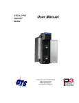
QTS-CLX-PVX
PROVOX®
User Manual
Module
Quest Technical Solutions
4110 Mourning Dove Court
Melbourne FL 32934
321 757-8483
www.qtsusa.com
Page ii QTS-CLX-PVX
Because of the variety of uses for the products described in this
publication, those responsible for the application and use of these
products must satisfy themselves that all necessary steps have been taken
to assure that each application and use meets all performance and safety
requirements, including any applicable laws, regulations, codes and
standards. In no event will Quest Technical Solutions be responsible or
liable for indirect or consequential damage resulting from the use or
application of these products.
Any illustrations, charts, sample programs, and layout examples shown
in this publication are intended solely for purposes of example. Since
there are many variables and requirements associated with any particular
installation, Quest Technical Solutions does not assume responsibility or
liability (to include intellectual property liability) for actual use based
upon the examples shown in this publication.
Throughout this manual we use notes to make you aware of safety
considerations.
Identifies information about practices or circumstances that can lead to
personal injury or death, property damage, or economic loss.
These warnings help to:
WARNING!
IMPORTANT!
TIP
•
identify a hazard
•
avoid the hazard
•
recognize the consequences
Identifies information that is especially important for successful
application and understanding of the product.
Identifies information that explains the best way to use the
QTS-CLX-PVX
Microsoft is a registered trademark of Microsoft Corporation.
Windows, Windows 95, Windows NT, Windows 2000, Windows XP and Vista are trademarks of
Microsoft Corporation.
ControlLogix, RSLinx and RSLogix 5000 are trademarks of the Allen-Bradley Company, Inc.
PROVOX is a registered trademark of FisherControls International LLC, a subsidiary of Emerson
Electric.
September 2009
QTS-CLX-PVX MODULE OVERVIEW
1
Part Number
2
Module Features
3
Power Requirements
3
Other Requirements
3
Package Contents
3
INSTALLATION
4
Prevent Electrostatic Discharge
4
Prepare the Chassis for Module Installation
Determine Module Slot Location
Insert the Module in the Chassis
4
4
5
Replacing a Module
6
Cabling and Termination
7
Software Installation
7
SUMMARY OF OPERATIONS
8
IMPORTANT CONSIDERATIONS
9
CONFIGURING THE MODULE IN RSLOGIX 5000
10
Module Configuration
Adding the Module
I/O Data Mapping
10
10
12
RSLINX
14
CONFIGURING THE I/O
15
ClxPvxCfg Software
15
Setting the Module Name
15
Setting the Module Mode
16
QTS-CLX-PVX Page iii
Configuring from a PROVOX Control I/O Bus
17
Mapping the I/O Data
What gets mapped
20
20
Uploading and Downloading Configurations
20
Saving a Configuration File
21
Opening a Configuration File
21
Clearing the Configuration
22
The Configuration Signature
22
Aliases
22
ACCESSING I/O DATA
25
Required Connections
25
Data Updates
25
Discrete Data
25
Analog Data Format
25
Diagnostic Data
27
USING MONITOR MODE FOR MIGRATION
31
TROUBLESHOOTING
32
ControlLogix Module LEDs
NET LED – Control I/O Bus Status
CLX LED – ControlBus Status
OK LED – Module Health
All LEDs Red
32
32
32
33
33
QTS-CLX-PVX Module 4-Character Display
33
RSLogix 5000
33
The Debug Log
34
Fatal Errors
34
UPDATING THE FIRMWARE
35
September 2009
Page iv QTS-CLX-PVX
Obtaining the Latest Software
35
APPENDIX:CLXPVXCFG
36
APPENDIX: CONFIGURATION FILE FORMAT
38
SPECIFICATIONS
41
QTS-CLX-PVX ControlLogix Module
41
SUPPORT
42
September 2009
QTS-CLX-PVX Module Overview
The QTS-CLX-PVX connects a ControlLogix controller to a PROVOX®
Control I/O bus.
The QTS-CLX-PVX is intended to be used to migrate PROVOX systems
to ControlLogix controllers. You can retain the PROVOX I/O as the
first step in the migration.
The module can act as a monitor or as a master on the Control I/O bus.
You select the mode by downloading different firmware to the module.
In monitor mode, the QTS-CLX-PVX sends PROVOX I/O input and
output data to input and status input data in the ControlLogix. It cannot
transmit on the bus.
In master mode, the ControlLogix sends output data to the
QTS-CLX-PVX, which then transmits it as output data on the PROVOX
Control I/O bus. The QTS-CLX-PVX sends PROVOX input data to
input data in the ControlLogix.
The QTS-CLX-PVX:
•
supports I/O bus redundancy
•
supports 20-series Control I/O files 1-16
•
supports up to 64 I/O cards. For larger systems, split the bus and
use two QTS-CLX-PVX modules.
Page 2 QTS-CLX-PVX
•
supports 10 series I/O with serial buffer card
•
does not support EIC or IDI
•
does not support Control I/O card redundancy
The QTS-CLX-PVX communicates with the ControlLogix processor
using scheduled connections. You configure the module as a Generic
Module in RSLogix 5000 with:
•
250 16-bit words of scheduled input data
•
248 16-bit words of scheduled output data
•
250 16-bit words of status input data
The Windows configuration program supplied with the module maps
Control I/O bus data to the scheduled data. It also:
•
uploads and downloads configuration data
•
downloads firmware to the module
•
saves and opens configuration files
•
exports aliases for use in your RSLogix 5000 application
Firmware Update
The module firmware can be updated using the Windows utility supplied
(see page 35).
Part Number
The part number of the module is QTS-CLX-PVX
September 2009
QTS-CLX-PVX Page 3
Module Features
The following figure shows the features of the module.
The module has:
•
A label that identifies the module, text QTS
Universal Comm
•
A 4-character scrolling display
•
3 LEDs, labelled NET, CLX, and OK, to indicate
the status of the I/O bus, the state of the connection
to the ControlLogix processor, and the internal state
of the module
•
2 BNC connectors to connect to the primary and
secondary I/O bus cables
The module supports insertion and removal under power.
The module is shipped in monitor mode, with a blank configuration.
Watchdog and Jabber Inhibit
A watchdog timer is implemented in the module’s hardware. If the
firmware does not kick the watchdog within the timeout period the
watchdog times out and generates a fatal error (see page 34) with error
code D1. In master mode, the module stops scanning and stops
communicating with the ControlLogix.
A jabber inhibit timer is implemented in the module’s hardware. If the
bus transmitter is on longer than 150% of the longest frame time, the
jabber inhibit forces the transmitter off and generates a fatal error (see
page 34) with error code D0. In master mode, the module stops scanning
and stops communicating with the ControlLogix.
Power Requirements
The QTS-CLX-PVX module requires 675 mA @ 24VDC and 5 mA @
5.1VDC from I/O chassis backplane.
Other Requirements
To use the Windows utility programs, you must have RSLinx software,
version 2.54 or later, with an activation. Use RSLinx Gateway or RSLinx
Professional software. Do not use RSLinx Lite.
Package Contents
•
QTS-CLX-PVX module
•
CD containing software and documentation
September 2009
Page 4 QTS-CLX-PVX
Installation
Prevent Electrostatic Discharge
The module is sensitive to electrostatic discharge.
ATTENTION: Electrostatic discharge can damage integrated circuits
or semiconductors if you touch backplane connector pins. Follow these
guidelines when you handle the module:
WARNING!
•
Touch a grounded object to discharge static potential
•
Wear an approved wrist-strap grounding device
•
Do not touch the backplane connector or connector pins
•
Do not touch circuit components inside the module
•
If available, use a static-safe work station
•
When the module is not in use, keep it in its static-shield packaging
Prepare the Chassis for Module Installation
Before you install the ControlLogix module, you must install and
connect a ControlLogix chassis and power supply. To install these
products, refer to the installation instructions you received with them.
Determine Module Slot Location
This example shows chassis slot numbering in a 4-slot chassis. Slot 0 is
the first slot and is always located to the right of the power supply. You
can use any size ControlLogix chassis and install the module in any slot.
Figure 1 Chassis Slots
September 2009
QTS-CLX-PVX Page 5
You can use multiple modules in the same chassis.
Insert the Module in the Chassis
The ControlLogix module is designed to be installed or removed while
chassis power is applied.
WARNING!
ATTENTION: When you insert or remove the module while
backplane power is on, an electrical arc can occur. This could cause an
explosion in hazardous location installations. Be sure that power is
removed or the area is nonhazardous before proceeding.
Repeated electrical arcing causes excessive wear to contacts on both the
module and its mating connector. Worn contacts may create electrical
resistance that can affect module operation.
September 2009
Page 6 QTS-CLX-PVX
Figure 2 Inserting the Module
Replacing a Module
If you are replacing an existing module with an identical one, and you
want to resume identical system operation, you must:
•
install the new module in the same slot.
•
run the configuration program and download the appropriate
configuration to the module.
•
check that it has the correct firmware, scanner or monitor version.
•
ensure that the data has been synchronized
September 2009
QTS-CLX-PVX Page 7
Cabling and Termination
WARNING!
Connecting the module disrupts bus traffic!
Connect the module at a time when it is safe to do so.
Connect the QTS-CLX-PVX like any other device on the Control I/O
bus.
The bus cable is 75-ohm RG-6, for example Belden 9290
Terminate both ends of the primary and secondary I/O bus using 75 ohm
resistors attached to the physical ends of the bus. There should be two
and only two terminators on each bus.
Refer to the following Emerson documents for details on cabling:
•
section 3.8 of "Installing and Maintaining the SRx Controller
Family", PN8.0:CL6640
•
Installing Control I/O Subsystem (PN2.1:CP6701)
•
Signal Wiring and Highway System Guidelines PN1:004
Software Installation
You must uninstall any previous version of the software before you can
install a new version. Use the Windows Control Panel Add and Remove
Programs to remove the old version.
Insert the CD supplied and run the program QtsPvx.msi on the CD to
install the Windows software.
September 2009
Page 8 QTS-CLX-PVX
Summary of Operations
The following is a short summary of the steps typically followed. Refer
to the appropriate manual section for details.
Step Operation
See page
1
Install the QTS-CLX-PVX module in the
ControlLogix chassis
4
2
Set the module mode to monitor (the default)
16
3
Connect the module to the Control I/O bus
7
4
Autoconfigure the module from the PROVOX
Control I/O bus
17
5
Configure the module in RSLogix 5000
10
6
Decide if you are going to use monitor mode to
develop and test your application
31
7
Disconnect the PROVOX master
8
Change the module mode to master
16
9
Save the configuration and download it to the
module
20
10
Create aliases for RSLogix 5000
22
11
Import the aliases into RSLogix 5000
22
12
Use the aliases to access data
September 2009
QTS-CLX-PVX Page 9
Important Considerations
The operation of the QTS-CLX-PVX is different in several important
ways from that of a standard ControlLogix module and in some ways
from a PROVOX controller.
It is essential that you be aware of the following:
•
the QTS-CLX-PVX in master mode write changes in the
ControlLogix output data table to PROVOX outputs even in program
mode. If you make a change in the output table, it will appear on the
bus
•
in master mode, if the I/O configuration in the QTS-CLX-PVX
changes, it is essential that you clear the ControlLogix output table
for the module before you connect it to the Control I/O bus
•
the QTS-CLX-PVX continues to scan the Control I/O bus even if the
the connection to the ControlLogix processor is lost. This is so that
I/O on the bus does not time out.
•
on the Control I/O bus, data is passed only when it changes. In
monitor mode, the QTS-CLX-PVX sees only data that changes while
it is connected to the bus. In master mode, the QTS-CLX-PVX
writes outputs only when they change and receives inputs only when
they change.
•
configuring the QTS-CLX-PVX module requires that you reset the
PROVOX controller. This can cause major disruptions to the
running system. Reset the controller only when you know it is safe
to do so. A reset can last up to 3 minutes.
•
if you switch from a real PROVOX scanner to a QTS-CLX-PVX
scanner, you should download the configuration to the QTS-CLXPVX. This forces a reset on the Control I/O bus. A reset is
necessary because the two scanners implement the bus token passing
slightly differently. A reset ensures that all files and cards update.
September 2009
Page 10 QTS-CLX-PVX
Configuring the Module in RSLogix 5000
You configure the module in RSLogix 5000 to set how much scheduled
data to transfer and how often to transfer it.
The terms input and output are relative to the ControlLogix.
In master mode, the ControlLogix sends output data to the
QTS-CLX-PVX, which then transmits it as output data on the PROVOX
Control I/O bus. The QTS-CLX-PVX sends PROVOX input data to
input data in the ControlLogix.
In monitor mode, the QTS-CLX-PVX sends PROVOX I/O input and
output data to input and status input data in the ControlLogix. It cannot
transmit on the bus.
You should always access data using the aliases generated by the
configuration program.
Module Configuration
Configure the module as a Generic module in RSLogix 5000.
The same ControlLogix configuration is used for master and monitor
modes of the QTS-CLX-PVX.
Adding the Module
To add the module to the I/O configuration in RSLogix 5000, you must
be offline.
1. If you are creating a new project, select File/New to create a new
project, give the processor a name, and enter the slot it occupies in
the ControlLogix rack.
2. Right click on the I/O configuration Folder, or on the bridge module
in the desired remote chassis in the I/O Configuration Folder, and
select New Module…
3. Expand the Other tab, select a module of Type 1756-MODULE
Generic 1756 Module and click OK.
September 2009
QTS-CLX-PVX Page 11
4. RSLogix 5000 displays the New Module dialog box.
5. Assign the module a Name and optionally a Description.
6. Set the Comm Format to Data – INT – With Status.
7. Set the Slot to match the slot number of the QTS-CLX-PVX module
in the chassis.
September 2009
Page 12 QTS-CLX-PVX
8. Set the Connection Parameters as shown above. Click OK.
9. Next set the RPI.
10. Click OK to accept the module
Selecting an RPI.
The module supports RPIs from 0.2 to 750.0 ms. The default RPI is 5
ms.
Select an RPI appropriate to the I/O bus scan time and to your process. It
makes no sense to use an RPI that is much faster than the bus or process
update time. Typical RPIs are from 100 to 150 ms.
Remote Connections
If you are using the QTS-CLX-PVX in a remote chassis, for example a
chassis connected to the controlling ControlLogix processor over
Ethernet or ControlNet, it may be necessary to increase the RPI, as the
intermediate network may not have sufficient bandwidth to support faster
updates (small RPIs).
I/O Data Mapping
The configuration program (see page 15) maps the I/O data to
ControlLogix tags.
The configuration program creates aliases to I/O data that you can import
into RSLogix 5000 to access I/O data. The alias names address data by
file, card and channel.
September 2009
QTS-CLX-PVX Page 13
Use these aliases to access data in any applications you develop. If the
mapping changes, you simply re-import aliases and the application
accesses the correct I/O location. The configuration program also creates
aliases to diagnostic data which is not easily accessible other than by
using the aliases.
September 2009
Page 14 QTS-CLX-PVX
RSLinx
When you right click on the module in RSLinx and select Properties,
RSLinx displays the following:
Parameter
Value
Device Name
CLX-PVX-MON (Monitor)
CLX-PVX-MAS (Master)
Vendor
832 (Quest Technical Solutions)
Product Type
12
Product Code
1052 (Monitor)
1051 (Master)
Revision
depends on firmware
Serial Number
depends on module
RSLinx Properties
To use the Windows utility programs, you must have RSLinx software,
version 2.54 or later, with an activation. Use RSLinx Gateway or RSLinx
Professional software. Do not use RSLinx Lite.
The installation CD contains EDS files for the QTS-CLX-PVX in
monitor and master modes.
September 2009
QTS-CLX-PVX Page 15
Configuring the I/O
ClxPvxCfg Software
The QTS-CLX-PVX module is supplied with a Windows configuration
tool, ClxPvxCfg.exe.
Use this configuration tool to:
•
Switch between monitor and master mode
•
Autoconfigure the monitor from an attached Control I/O bus
•
Convert the configuration for master mode
•
Map I/O data to ControlLogix scheduled connections
•
Save and load configuration files
•
Download and upload configurations
•
Set the RSLinx path to the QTX-CLX-PVX module
•
Export aliases for I/O data for import into RSLogix 5000, for both
master and monitor modes
•
Update the module firmware
ClxPvxCfg is an offline configuration tool; any changes must be
downloaded to the QTS-CLX-PVX module.
Setting the Module Name
To set the module name, right click on the QTS-CLX-PVX at the root of
the tree and select Edit Module Properties.
September 2009
Page 16 QTS-CLX-PVX
The QTS-CLX-PVX Module Properties dialog appears.
Enter the Module Name. It can be up to 15 characters long. It should
follow the rules for naming ControlLogix aliases; it should contain only
alphanumeric characters and the underscore. Click OK to accept the
name.
The name is displayed on the 4-character display and is used by
ClxPvxCfg to build aliases for ControlLogix data.
The default name assigned when you perform an autoconfiguration is
Auto_Scan.
The name should be unique so that if you have more than one
QTS-CLX-PVX module, the alias names associated with each module
are unique.
TIP
Use the same name that you assign the module in RSLogix 5000 to make
it easy to associate aliases with the module.
You can use the name of the controller you are monitoring, for example,
SRx101.
Setting the Module Mode
To switch between modes or to update module firmware, select
Actions/Change Module Mode… Changing the module mode downloads
firmware to the card.
If the RSLinx path has not been set, select the module in the tree.
The Set QTS-CLX-PVX Mode dialog appears.
It shows the current mode and lets you select the firmware to download.
September 2009
QTS-CLX-PVX Page 17
IMPORTANT!
If you change the mode (monitor to master or master to monitor), any
configuration on the module is cleared. If the firmware you download is
the same as the firmware already on the module (for example, if you are
updating firmware), the configuration is unaffected.
Click Apply to download the firmware.
When the firmware download is successful, the module displays the
following message and shows the version of firmware downloaded.
Click OK to clear the message, then click Done.
If you change the module mode from master to monitor or from monitor
to master:
•
the configuration in the configuration program is converted to the
new mode
•
data mappings change
The ControlLogix controller with the connection to the module must be
in program mode when you change mode. If the processor is in run
mode, the following message appears.
The QTS-CLX-PVX displays the module and firmware and version on
the 4-character display.
Configuring from a PROVOX Control I/O Bus
The QTS-CLX-PVX must be configured by capturing configuration
information sent by a PROVOX master to a running PROVOX system.
WARNING!
Connecting the module to the Control I/O disrupts bus traffic!
Connect the module only at a time when it is safe to do so.
September 2009
Page 18 QTS-CLX-PVX
Use the following steps to configure the QTS-CLX-PVX.
1. Connect the module, in monitor mode, to a running PROVOX bus.
2. Use the Actions/Start Auto Configuration menu command or use
Auto Configuration toolbar command to start an auto-configuration
cycle.
WARNING!
Resetting the PROVOX controller disrupts the running system!
Reset the controller only at a time when it is safe to do so.
3. Reset the PROVOX master. The QTS-CLX-PVX captures the
configuration data the master sends out and passes it to the
configuration program, which analyzes it and builds the tree.
4. Download the captured configuration to the QTS-CLX-PVX.
5. Export aliases from the configuration tool to a file.
6. Import those aliases into RSLogix 5000.
7. Use the aliases to monitor data on the PROVOX bus.
If the module does not capture the configuration within a timeout period
(approximately 60 seconds), it displays this message.
September 2009
QTS-CLX-PVX Page 19
Note: If the ControlLogix processor previously had a connection open to
the QTS-CLX-PVX module when the autoconfiguration timed out, that
connection remains open, even though there is now no configuration on
the module. However, if the module has no configuration, itwill not
accept new connections.
WARNING!
If the configuration in the PROVOX controller changes, you must repeat
this procedure to capture the new configuration. Failure to do so results
in the monitored values being incorrect.
Card and Data Limits
The QTS-CLX-PVX supports a maximum of 64 cards in monitor or
master mode. If there are more than 64 cards in the captured
configuration, ClxPvxCfg displays a message. You will have to delete
some cards from the configuration. Right click on the card and select
Delete.
Note: You cannot delete a 10 Series Communication Card. It disappears
automatically when you delete all the other cards in the file.
In addition there are limits on the amount of available ControlLogix data
space. Depending on the type of cards, you may exceed one of these
limits without exceeding the maximum of 64 cards. In monitor mode,
you will have to remove some cards from the configuration or use two
QTS-CLX-PVX modules as monitors. In master mode, you can split the
bus and use a QTS-CLX-PVX master on each bus.
Monitor-Only Files
A monitor-only file is created under two circumstances:
•
the captured configuration contains an unsupported card type
•
a card in the PROVOX controller’s configuration is not responding
on the bus
A monitor-only file can be used with the QTS-CLX-PVX in monitor
mode but cannot be converted for use in master mode.
September 2009
Page 20 QTS-CLX-PVX
Mapping the I/O Data
When you autoconfigure the monitor from the PROVOX bus, the
configuration tool automatically maps the I/O data to locations in the
ControlLogix scheduled input and status input data.
When you change the module to master mode, the configuration tool
remaps the data to ControlLogix scheduled input and output data.
If you delete any cards from the configuration, all mappings are cleared.
Unassigned I/O addresses are shown as Undefined in the tree. To remap
the data, select Actions/Auto-allocate Logix Addressing.
Whenever the data mapping changes, make sure you export a new alias
file and re-import it into RSLogix 5000 so that you are using the correct
addresses for data.
Failure to do so will result in writing incorrect data and may result in
injury or death.
WARNING!
If the QTS-CLX-PVX is in master mode and data mappings change,
make sure you clear the output data table for the module in the
ControlLogix processor before you connect the QTS-CLX-PVX to the
Control I/O bus.
What gets mapped
Master Mode
PROVOX inputs (AI, DI) are mapped to ControlLogix inputs (path:I).
PROVOX outputs (AO, DO) are mapped to ControlLogix outputs
(path:O)
Diagnostics are mapped to ControlLogix inputs and status inputs
(path:S).
Monitor Mode
PROVOX inputs (AI, DI) are mapped to ControlLogix inputs (path:I).
PROVOX outputs (AO, DO) are mapped to ControlLogix status inputs
(path:S).
Diagnostics are mapped to ControlLogix inputs and status inputs.
Uploading and Downloading Configurations
To download a configuration to the QTS-CLX-PVX, select
Actions/Download Configuration or use the Download Configuration to
Module button on the toolbar.
September 2009
QTS-CLX-PVX Page 21
To upload a configuration from the QTS-CLX-PVX, select
Actions/Upload Configuration or use the Upload Configuration from
Module button on the toolbar. The uploaded configuration will be given
the default file name Untitled.
If the RSLinx path to the module has not been set when you upload or
download, an RSLinx Path Selection window opens.
If the ControlLogix processor with the connection to the QTS-CLX-PVX
is in run mode when you download, the following message is displayed.
TIP
In master mode, to do the equivalent of a PROVOX reset, download the
configuration to the module.
Saving a Configuration File
To save a configuration to disk, select File/Save or File/Save As.
Opening a Configuration File
To open a configuration file, select File/Open..
September 2009
Page 22 QTS-CLX-PVX
This does not change the configuration in the module; the configuration
in the module changes only when you download.
Clearing the Configuration
To clear the configuration in the program, select File/New.
This does not change the configuration in the module; the configuration
in the module changes only when you download.
The Configuration Signature
The configuration signature is displayed at the root of the tree. It can be
used to determine if there are differences between a configuration file
and the configuration in the module.
Open the configuration file and note the configuration signature. Now
upload the configuration from the module and compare the configuration
signatures. If they are the same, the configurations are identical.
Aliases
The configuration tool creates aliases for I/O data that can be exported
and imported into RSLogix 5000.
You should write programs in terms of these aliases rather than using
absolute addresses. If the mapping of the I/O data changes, simply
reimport the new aliases and the program will point to the new data
locations.
To export aliases, select Files/Export Tags…
Enter the RSLinx Path Specifier to set the location of the module. In the
example shown, the module is in slot 0 of the Local chassis.
To determine the RSLinx Path Specifier, look at the raw tags for the
module in RSLogix 5000.
September 2009
QTS-CLX-PVX Page 23
The RSLinx Path Specifier includes everything up to but not including
the colon before I, O, C or S. In the example shown, it is Local:3
Use the Select File Name button to enter the file location.
If you are using monitor mode to develop your application, check the
Create Temp Array Alias Tags checkbox. You should also create an
array of 250 INTs with name TempPvxOutputArray in the ControlLogix.
Click OK to create the alias file.
WARNING!
If you change the I/O or ControlLogix configuration, re-import aliases so
that the ControlLogix processor uses the correct addresses and clear the
ControlLogix output table so that values don’t get written to incorrect
addresses.
Importing Aliases in RSLogix 5000
To import the alias file into RSLogix 5000, you must be offline. Select
Tools/Import… and import the alias file.
TIP
If you have changed mode on the QTS-CLX-PVX, delete any aliases
you previously imported into RSLogix 5000 before you import the new
aliases.
Alias Format
ClxPvxCfg builds each alias name from the Module name and address
information supplied by the configuration program
The ControlLogix data address is built from the RSLinx Path Specifier
you enter and the data mappings created by the configuration program.
For example,
ALIAS,"","D3R_Mas_AI_F01C01C01","D3R_Mas_AI_F01C01C01","","Local:0:I.D
ata[2]""
In this example, the module is in slot 0. The alias is for an analog input
at PROVOX address File 1, card 1, channel 1, which is mapped to
September 2009
Page 24 QTS-CLX-PVX
ControlLogix address input data at offset 2. The module name is
D3R_Mas.
To build the alias name, ClxPvxCfg appends an underscore and
F01C01C01 to the module name. The module is in slot 0 of the local
chassis so the alias data address is Local:0:I.Data[2]
September 2009
QTS-CLX-PVX Page 25
Accessing I/O Data
Required Connections
In master mode, the QTS-CLX-PVX does not begin scanning the I/O bus
until all ControlLogix connections to the module are present.
If the connection is later closed, the QTS-CLX-PVX continues scanning
the bus. Inputs do not update in the ControlLogix while the connection
is closed and outputs do not update.
In monitor mode, the module does not wait for ControlLogix
connections.
Data Updates
It is important to remember always that the PROVOX Control I/O bus
updates data only when the data changes.
Any changes that occur when the module is not connected to the bus will
not be captured.
Discrete Data
Use the aliases created by ClxPvxCfg to access discrete data to ensure
that you are using the correct address and bit.
Analog Data Format
Analog values on the Control I/O bus are expressed in PROVOX Percent
Format. The number is shown in the PROVOX controller as a percent
with 3 decimal places. The range is -13.969% to +113.970%.
Each 16-bit word consists of:
upper byte = signed byte, represents the whole number part of the
percentage
lower byte = unsigned byte, represents the fractional part, as a fraction of
256
Some examples:
Number, percent
High byte, hex
Low byte, hex
Number, hex
-13.97%
F2
08
F208
-1.75%
FE
40
FE40
0.00%
00
00
0000
1.75%
01
C0
01C0
25%
19
00
1900
25.25%
19
40
1940
September 2009
Page 26 QTS-CLX-PVX
Number, percent
High byte, hex
Low byte, hex
Number, hex
50%
32
00
3200
75%
4B
00
4B00
100%
64
00
6400
113.97%
71
F8
71F8
Modules like thermocouples linearize the inputs to percent of range, 1 to
5V.
Add-on instructions for RSLogix 5000 to convert between PROVOX
percent and ControlLogix real numbers are available from the downloads
area of the Rockwell Automation support website
http://samplecode.rockwellautomation.com/
In the Sample Code Library, search for “AOI for QTS-CLX-PVX PROVOX
Module REV”
Converting PROVOX Percent Format to ControlLogix Real
For positive values (high bit of upper byte clear), add the whole number
part (upper byte) to the fraction (lower byte divided by 256).
For negative values (high bit of upper byte set), subtract 256 from the
whole number part and add the fractional part.
Example 1:
To convert 1940 hex, first note that the number is positive (high bit
clear).
Convert the whole number part, 19 hex, to 25 decimal. The fractional
part is 40 hex = 64 decimal. Convert it to a fraction = 64/256 =.25 and
add the whole number part to get 25.25%.
Example 2:
To convert E780 hex, first note that the number is negative (high bit set).
Subtract 256 from the whole number part (E7 hex = decimal 231), to get
-25. The fractional part is 80 hex =128 decimal. Convert it to a fraction
= 128/256 = .5. Add the parts to get -25 + .5 = -24.5%
Converting ControlLogix Real to PROVOX Percent Format
For positive values:
1. Convert the whole number part and store it in the upper byte.
2. Multiply the fractional part by 256 and store it in the lower byte.
For negative values:
September 2009
QTS-CLX-PVX Page 27
1. First add 256 to the whole part. If the fractional part is non-zero
(in practice, greater than .039), subtract 1 from the result. Store
the result in the upper byte.
2. Subtract the fractional part from 1 and multiply the result by 256.
Store the result in the lower byte.
Example 1:
To convert 74.5%, first convert 74 to hexadecimal 4A and store it in the
upper byte. Multiply .5 by 256 to get 128 = 80 hex and store it in the
lower byte.
The result is 4A80 hex.
Example 2:
To convert -1.75%:
Since the number is negative and the fractional part is non-zero, first add
256 to -1 to get 255 and subtract 1. Put 254 = FE hex in the upper byte.
The fractional part is .75. Subtract it from 1 to get .25, multiply by 256
to get 64 = 40 hex, and put 40 hex in the lower byte.
The result is FE40 hex.
Diagnostic Data
The QTS-CLX-PVX maintains diagnostic counters and other diagnostic
status information.
Primary and Secondary File Error Table
In both master and monitor modes, the first two words of ControlLogix
input data contain a table that shows which card files have
communication problems on either the primary or secondary bus.
The first word, at offset 0, corresponds to the primary.
The second word, at offset 1, corresponds to the secondary.
In each word, bit 0 corresponds to file 1, bit 1 corresponds to file 2, and
so on.
Bit
15 14 13 12 11 10
9
8 7 6 5 4 3 2 1 0
File 16 15 14 13 12 11 10 9 8 7 6 5 4 3 2 1
The bit is set if there’s at least one card in the file with a problem on that
bus.
The bits are 0 for unconfigured card files.
TIP
You can use the file error tables to determine if a particular piece of data
is valid.
September 2009
Page 28 QTS-CLX-PVX
If there’s a problem with the connection to the QTS-CLX-PVX module,
the ControlLogix processor sees all bits in this table as set to 1.
Integrity Bits
In master mode, PROVOX integrity bits for each configured card are
mapped to ControlLogix status inputs. Use the aliases created by
ClxPvxCfg to access the integrity bits.
Channel Status Bits
In master mode, PROVOX channel status bits for each channel are
mapped to ControlLogix status inputs. Use the aliases created by
ClxPvxCfg to access the channel status bits.
Diagnostic Counters
In both monitor and master mode, the module maintains diagnostic
counters that can be used to diagnose bus problems.
Use the aliases generated by the configuration program to access the
diagnostic counters.
The counters are slightly different for monitor and master modes.
Monitor Diagnostic Counters
Name
Description
StatPrimRxGood
Number of good packets received on
primary channel
StatPrimAbortErr
Number of abort packets on primary
channel
StatPrimNoiseErr
Number of error packets caused by noise on
primary channel
StatPrimFrameErr
Number of packet frame errors on primary
channel
StatPrimCrcErr
Number of packets with CRC errors on
primary channel
StatPrimPacketLenErr
Number of short packets received on
primary channel
StatSecRxGood
Number of good packets received on
secondary channel
StatSecAbortErr
Number of abort packets on secondary
channel
StatSecNoiseErr
Number of error packets caused by noise on
secondary channel
StatSecFrameErr
Number of packet frame errors on
September 2009
QTS-CLX-PVX Page 29
Name
Description
secondary channel
StatSecCrcErr
Number of packets with CRC errors on
secondary channel
StatSecPacketLenErr
Number of short packets received on
secondary channel
September 2009
Page 30 QTS-CLX-PVX
Master Diagnostic Counters
Name
Description
StatPrimTxGood
Number of good packets sent on primary
channel
StatPrimRxGood
Number of good packets received on
primary channel
StatPrimAbortErr
Number of abort packets on primary
channel
StatPrimNoiseErr
Number of error packets caused by noise on
primary channel
StatPrimFrameErr
Number of packet frame errors on primary
channel
StatPrimCrcErr
Number of packets with CRC errors on
primary channel
StatPrimPacketLenErr
Number of short packets received on
primary channel
StatPrimRxTimeOut
Number of packet timeout errors on primary
channel
StatSecTxGood
Number of good packets sent on secondary
channel
StatSecRxGood
Number of good packets received on
secondary channel
StatSecAbortErr
Number of abort packets on secondary
channel
StatSecNoiseErr
Number of error packets caused by noise on
secondary channel
StatSecFrameErr
Number of packet frame errors on
secondary channel
StatSecCrcErr
Number of packets with CRC errors on
secondary channel
StatSecPacketLenErr
Number of short packets received on
secondary channel
StatSecRxTimeOut
Number of packet timeout errors on
secondary channel
September 2009
QTS-CLX-PVX Page 31
Using Monitor Mode for Migration
You can use monitor mode on the QTS-CLX-PVX to migrate existing
PROVOX applications to ControlLogix.
In monitor mode, the QTS-CLX-PVX captures live inputs and outputs
from the PROVOX bus.
You first create an array of 250 INTs with name TempPvxOutputArray
in the ControlLogix.
The configuration program creates aliases for PROVOX inputs and
outputs and for dummy outputs in the temporary array.
You import those aliases into RSLogix 5000, then create a new
ControlLogix application that reads live inputs from the PROVOX bus
and writes outputs to the temporary array, always using the aliases from
ClxPvxCfg.
You compare the outputs from the new ControlLogix application (in the
temporary array) with the live outputs from PROVOX.
When you are satisfied that the new application duplicates the behaviour
of the existing PROVOX control application (state of outputs and
timing), disconnect the PROVOX controller and switch the
QTS-CLX-PVX module to master mode.
Export aliases from ClxPvxCfg in master mode and import them into
RSLogix 5000. The names for the output aliases will be the same as
those that pointed to the temporary array but now they will point to the
corresponding PROVOX outputs. Your new ControlLogix application
will write to the real outputs instead of the temporary array. Since you
developed your application using these aliases, no further changes will
be necessary.
You will start up with a ControlLogix application that has been tested
and proved to duplicate the behaviour of the previous PROVOX control
application.
Example:
This is the alias ClxPvxCfg generated in monitor mode for a PROVOX
monitored output
ALIAS,"","SRx101_AO_F01C01C01","SRx101_AO_F01C01C01","","TempPvxOu
tputArray[0]"
and this is the alias it generated for the same output in master mode
ALIAS,"","SRx101_AO_F01C01C01","SRx101_AO_F01C01C01","","Local:3:O.D
ata[0]"
The alias names are the same but in the first case the program would
write to the temporary array; in the second it would write to a
ControlLogix output.
September 2009
Page 32 QTS-CLX-PVX
Troubleshooting
ControlLogix Module LEDs
The module has three status LEDs to indicate the state of internal
operations. The LEDs are labeled NET, CLX and OK.
NET LED – Control I/O Bus Status
The NET LED shows the status of I/O communication. The NET LED
states are the same for master and monitor modes.
In order of priority, highest first, these are:
Color
Meaning
Solid Red
Card offline - happens when there is no configuration
on the module
Flashing red
Net LED blinks RED for 1 second with every bus error.
A burst of bus errors causes the LED to stay red for
longer than 1 second.
Yellow
One or more configured cards is offline (can't be
reached via primary or secondary links)
Green
All configured cards are online
CLX LED – ControlBus Status
The CLX LED indicates the status of communication with the
ControlLogix processor.
Color
Meaning
Green
All required connections are open
Yellow
Idle, no scheduled connections, ControlLogix PLC
does not have a configuration for the QTS-CLX-PVX
module or the configuration is inhibited.
Flashing
Red/Off
The module has returned a CIP error within the last
second - no scheduled connections, QTS-CLX-PVX
module configuration not present
Solid Red
The module has returned a CIP error - no scheduled
connections.
September 2009
QTS-CLX-PVX Page 33
OK LED – Module Health
The OK LED indicates module health. A red LED indicates that module
startup diagnostics have failed or a major module fault has occurred.
Green indicates that the module has passed all power-up diagnostics and
is functioning normally.
All LEDs Red
If all three LEDs are solid red and the 4-character display shows
something like M#66, this indicates that a fatal error has occurred. Refer
to page 34 for information on clearing fatal errors. If a fatal error occurs,
clear the fatal error, save the file and contact QTS Technical Support.
QTS-CLX-PVX Module 4-Character Display
The 4-character display shows the firmware in the module, either
CLX-PVX-MON or CLX-PVX-MAS, followed by the firmware version
number, and the Module Name you entered in the module configuration
(see page 15).
If there is no configuration in the module, the display shows
<NoConfig> instead of the module name.
RSLogix 5000
If there is a problem with the connection to the module, it is shown with
a yellow triangle in the I/O Configuration tree
The Connection Tab for the QTS-CLX-PVX module displays an error
message if there is a problem with the connection to the module.
September 2009
Page 34 QTS-CLX-PVX
If the module has no PROVOX configuration, it refuses connection
requests from the ControlLogix processor and returns an error.
The Debug Log
The firmware on the module maintains a log of informational and
diagnostic messages that can be useful in determining the cause of
configuration and I/O bus problems.
To view the log, run the program LogMon from the Start Menu.
Fatal Errors
Fatal errors occur when the firmware on the module encounters an
unexpected condition. The module stops running, turns all three LEDs
red, and displays the fatal error number on the 4-character display. The
module also records its state at the time the fatal error occurred in a log.
To clear the fatal error and capture the fatal error log:
1. Cycle power on the module. The 4-character display should show
“FatalErrorCapture required”.
2. Run the utility FatalCapt.exe from the subdirectory Tools where you
installed the configuration tool (ususally Program Files\QtsPvx)
3. Store the fatal error log to a file. This also clears the fatal error on the
module.
Contact QTS technical support. Provide them with the fatal error log,
which will help diagnose the cause of the problem.
September 2009
QTS-CLX-PVX Page 35
Updating the Firmware
The module firmware is updated using the configuration program.
Select Actions/Set Module Mode.
To update the firmware, set the mode to match the firmware already
loaded in the module.
Set Module Mode uses the firmware files (*.qtf) in the same directory as
ClxPvxCfg.exe.
The configuration program displays the version after the firmware has
been downloaded.
The module displays the firmware and version currently loaded on the
4-character display.
Obtaining the Latest Software
Version numbers and software for the most recent release are available
from the QTS website, www.qtsusa.com
September 2009
Page 36 QTS-CLX-PVX
Appendix:ClxPvxCfg
ClxPvxCfg is the configuration program for the QTS-CLX-PVX module.
It is an offline configuration program; you must upload or download
configuration data.
Summary of Operations
Menu Item
Description
File Menu
New File
Close the configuration in ClxPvxCfg and open a
new file
Open File
Open a configuration file from disk
Save File
Save a configuration file to disk
Save File As
Save a configuration file to disk under a new name
Export Alias File
Export a file that contains aliases for import into
RSLogix 5000
Recent File list
Open a file that has been previously opened
Exit
Exit ClxPvxCfg
Actions Menu
Upload Config
Upload a configuration from the QTS-CLX-PVX to
ClxPvxCfg
Download Config
Download a configuration from ClxPvxCfg to the
QTS-CLX-PVX module
Start Auto Configuration
Monitor mode only. Capture a configuration from a
Control I/O Bus
Auto Allocate CLX Addressing
Assign ControlLogix data addresses
Change Module Mode
Download firmware to the QTS-CLX-PVX module,
to switch between monitor/master modes or to
update firmware
If there is a configuration in ClxPvxCfg and you
change modes, the configuration is also converted.
Set RSLinx Path
Set or change the path to a QTS-CLX-PVX module
View Menu
Toolbar
Display/hide the toolbar
Status Bar
Display/hide the status bar
Help Menu
Help Topics
Display the help main window
About ClxPvxCfg
Display about box, shows version
September 2009
QTS-CLX-PVX Page 37
Menu Item
Description
Right Click on Module
Edit Module Properties
Change module name
Auto-allocate CLX Addressing
see above
Change Module Mode
see above
Right click on card
Delete Card
Delete a card from the configuration
Also clears all ControlLogix addresses
View Card Properties
Display cofiguration data for a card
September 2009
Page 38 QTS-CLX-PVX
Appendix: Configuration File Format
Configuration files for the QTS-CLX-PVX are text files. The following
information is provided for reference only. The manual editing of
configuration files should be done with the direction of QTS customer
support personnel.
The first line of the configuration file consists of:
Number of Cards: 39 Name: D3R_Mas Mode: 54cd3514 Options:
01010101 Cfg Id: 43960cce
Number of cards = the number of configured card to follow
Name: the module name
Mode = hexadecimal value that indicates whether this is a master or
monitor file (54cd3514 – master, 54cd3512 - monitor)
Options: the starting card in each of the four scan segments
Cfg Id: the hexadecimal configuration ID calculated by ClxPvxCfg.exe.
This is followed by card definitions for each card.
Card definitions
A typical card definition consists of:
Byte Address: 001 Type: 13 State: 9
Priority: 01 CfgMask: ffff IpMask: ffff OpMask: 0000
TokenLst: 2
2
2
ChanType: 14
14 14 14
14
ChanParam: 0
0
2
14
0
0
14
14
0
0
14
0
0
14
14
0
0
14
0
14
0 0
14
0
14 14
0
0
Input Copy Table
1 4 32
Output Copy Table
0 0 0
The Byte Address is the address of the card, stored in decimal; however,
if you convert it to hex it is more meaningful: upper nibble = cardfile -1,
lower nibble = card number
i.e. decimal 17 = 11 hex = card file 2, card 1
The Type is the base card type.
Supported card types are:
September 2009
QTS-CLX-PVX Page 39
Card Type
Value, Hex
Value, Decimal
AIO_CARD_TYPE
0D
13
DIO_CARD_TYPE
0F
15
TPO_CARD_TYPE
11
17
PCI_CARD_TYPE
16
22
State is used with card redundancy, which is not supported. Always set
the value to 9.
Priority defines the card priority, 1,2 or 4
CfgMask, IpMask and OpMask define which channels are configured,
which channels are inputs and which channels are outputs, respectively.
TokenList gives the card address this card will give the token to (for all 4
scan segments)
ChanType is an array of 16 bytes, one byte per channel starting at
channel 1
Possible channel types are:
Channel Type
Value, Hex
Value, Decimal
DO_MOMENTARY_TYPE_CODE
04
4
DO_LATCHING_TYPE_CODE
06
6
DI_CHANNEL_TYPE_CODE
05
5
PCI_CHANNEL_TYPE_CODE
16
22
TPO_CONTINUOUS_TYPE_CODE
12
18
TPO_ONESHOT_TYPE_CODE
13
19
AI_CHANNEL_ISO_1TO5
0b
13
AI_CHANNEL_ISO_0TO10
0c
12
AI_CHANNEL_SINGLE_ENDED
0e
14
AI_CHANNEL_LOW_VOLTAGE
10
16
AI_CHANNEL_TYPEJ_LOW
22
34
AI_CHANNEL_TYPEJ_HIGH
23
35
AI_CHANNEL_TYPEK_HIGH
24
36
AI_CHANNEL_TYPEK_LOW
25
37
AI_CHANNEL_TYPE_T
26
38
AI_CHANNEL_TYPE_E
27
39
AI_CHANNEL_TYPE_R
28
40
September 2009
Page 40 QTS-CLX-PVX
Channel Type
Value, Hex
Value, Decimal
AI_CHANNEL_LOW_SP1
29
41
AI_CHANNEL_LOW_SP2
2a
42
AI_CHANNEL_TYPE_B
2e
46
AI_CHANNEL_TYPE_S
2f
47
AI_CHANNEL_RTD_270_140
36
54
AI_CHANNEL_RTD_148_212
37
55
AI_CHANNEL_RTD_100_600
38
56
AI_CHANNEL_RTD_32_392
39
57
AI_CHANNEL_RTD_32_1112
3a
58
AI_CHANNEL_RTD_100_500
3b
59
AI_CHANNEL_RTD_32_300
3c
60
AI_CHANNEL_RTD_SPEC
3d
61
AO_CHANNEL_TYPE_CODE
02
2
ChanParam is an array of 16 bytes containing any channel parameters
Input Copy Table and Output Copy Table define where the input and
output data for the card are copied to or from in the ControlLogix.
The layout is:
CLX area, CLX Offset (byte offset), Length (bytes)
Area
ControlLogix data area
0
no data mapped
1
input (I.Data[])
2
status (S.Data[])
3
output (O.Data[])
If you edit the configuration file manually, set the entries for the copy
tables to 0 and let the configuration tool assign ControlLogix addresses.
September 2009
QTS-CLX-PVX Page 41
Specifications
QTS-CLX-PVX ControlLogix Module
Parameter
Specification
Module Location
ControlLogix chassis
Function
ControlLogix module for PROVOX Control I/O
bus
Maximum Backplane
Current Load
675 mA @ 24VDC and 5 mA @ 5.1VDC
from I/O chassis backplane
Power dissipation
20W maximum
Environmental
Conditions:
Operational
Temperature
0-60°C (32-140°F)
Storage Temperature
–40 to 85°C (–40 to 185°F)
Relative Humidity
5-95% without condensation
September 2009
Page 42 QTS-CLX-PVX
Support
Technical support is available from Quest Technical Solutions.
Quest Technical Solutions
4110 Mourning Dove Court
Melbourne FL 32934
321 757-8483
website: qtsusa.com
email: [email protected]
If you need to make a return, contact QTS to obtain a return
authorization number.
September 2009