1
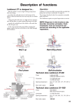
Laddomat® 21 Charging Unit User and installation instructions NOTE! Diagrams in this brochure only describe connection principles. Each installation must be measured and carried out according to the applicable regulations. Manufacturer Termoventiler AB Sweden www.termoventiler.se LM21_Manual_E.indd 812082-E 061128 Part.No. 11 23 78 1 The Laddomat 21 is designed to... C o n n e c tio n to to p o f b o ile r ...allow the boiler to reach a high working temperature soon after firing. B a ll v a lv e 1 1 /4 " IG ...to heat the cold tank water in the bottom of the boiler so that the boiler does not rust away through corrosion. T h e rm o m e te r …charge the tank with water at a high and even temperature and low flow, to ensure optimal separation in the tank. F ille r c a p In te g ra te d th e r m a l v a lv e …in the event of a power cut stopping the pump, transfer the heat in the boiler to the tank through self-circulation. 3 5 4 …transfer the residual heat in the boiler to the tank after the fire has gone out. In te g ra te d p u m p W ilo R S 2 5 6 /3 T h e rm o m e te r Operation The Laddomat 21 functions fully automatically provided that pump start and stop is automated. See page 4. B a ll v a lv e 1 1 /4 " IG T h e rm o m e te r The settings described in this User manual are normally made only once. C o n n e c tio n to b o tto m o f b o ile r The Laddomat requires no special supervision or service. C o n n e c tio n to ta n k B a ll v a lv e 1 1 /4 " IG D ir tp o c E a s y to P re v e n in te r r u p A u to m a tic v a lv e fo r s e lf- c ir c u la tio n in e v e n t o f a p o w e r c u t k e t c le a n ts o p e r a tin g tio n s 2 5 4 The main parts of a wood burning set-up E x p v e s s e l B y -p a s s v a lv e a u to m a tic H o t w a te r C o ld w a te r M ix e r v a lv e S a fe ty v a lv e F lu e th e rm o s ta t L a d d o m a t 2 1 2 P lu n g e r C o v e r R a d ia to r R a d ia to r p u m p B y - p a s s v a lv e S p r in g T h e rm o s ta t c a r tr id g e E le c tr ic h e a te r D o m e s tic w a te r h e a te r F illin g v a lv e B o ile r R o o m s e n s o r F lo w s e n s o r C h e c k v a lv e w a s h e r S to ra g e ta n k C o v e r H o ld e r S p r in g Description of functions Starting the boiler To achieve a high level of efficiency and low emissions of unburned substances, it is important that the boiler reaches working temperature quickly. This is achieved by the circulation pump starting as firing starts. This prevents cold water from the bottom of the tank cooling the boiler unnecessarily, through selfcirculation. The circulation pump can be started in three different ways, see page 4. Firing has started in the illustration to the right. The pump has started. The thermostat cartidge has not started to open yet. The valve plate of the self-circulating valve is kept closed by the water pressure from the circulation pump. Start up Operating phase The boiler has reached operating temperature. The thermostat cartridge has opened and mixes in cold water from the tank. The mixed water entering the bottom of the boiler has a temperature of about 5–20°C below the opening temperature of the thermostat cartridge. The higher the output of the boiler and the higher the temperature of the water exiting the boiler, the more cold water is mixed in from the bottom of the tank. This is the same characteristic that allows Laddomat 21 to separate effectively = charging to the tank under all different operating conditions in different boilers. Final phase Operating phase During the final phase of charging the by-pass port in Laddomat 21 is completely closed to the top of the boiler. All water is routed to the tank which becomes fully charged. Self circulation when the burner has stopped If a flue thermostat or similar equipment is installed, it will stop the pump immediately after the fire goes out. The advantage of stopping the pump quickly after the fire goes out is that the cool return water from the radiator circuit flows into the bottom of the boiler through selfcirculation. The stored heat in the boiler is then transferred to the top of the tank, and the house then benefits from it. Stopping the pump when heating ceases, either manually or automatically, is important for one further reason. The hot water in the tank will otherwise be mixed with cold radiator water down to the closing temperature of the thermostat cartridge. If the tank is heated to 90°C and the thermostat cartridge closes at 75° the whole tank falls to this temperature if the pump is not switched off . Final phase Self circulation in event of a power cut If a power cut occurs during firing, self-circulation starts automatically through the easily opened check valve, on the condition that the water in the tank is colder than the water in the boiler. The self-circulation power is created by the weight difference between lighter hot water and heavier cold water. If the tank is completely heated all the way to the bottom, selfcirculation will be limited, and the boiler could still hit boiling point. This boiling can be stopped by feeding a small quantity of cold water directly into the bottom of the boiler through the system filling tap. In the event of a sustained power cut, the whole house can be heated through selfcirculation, if the pipe-runs and dimensions are suitable. The firing should be matched to the output which can be transferred to the storage tank through self-circulation. Self-circulation 3 Installation Dimensioning Generous pipe dimensions and short lengths guarantee operating reliability, even when the demand for heat is high. This also allows effective self-circulation in the event of power cuts. Pipe dimensions at a maximum boiler to tank distance of 3 m. Boilers up to: 35 kW min. 28 cu pipe or R25 50 kW min. 35 cu pipe or R32 80 kW min. 42 cu pipe or R40 The dimensions must be increased for longer pipes. Starting and stopping the charging pump It is important to start the pump as soon as the firing starts to ensure that the boiler heats up rapidly. Stopping the pump quickly when the fire has gone out will make the hot water self-circulate from the top of the boiler to the storage tank. Some boilers have integrated thermostats to control the pump. Check that this control system operates correctly with the boiler. If there are special requirements for self-circulation, the pipes must be dimensioned accordingly. NOTE Not included in delivery F lu e th e r m o s ta t ® The Laddomat 21 must always be connected in the upright position as shown in the diagrams. If fitte d th e rm o b e c o n in p a r a , w a te r s ta t to n e c te d lle l 0 1 S w itc h Connection Position Laddomat 21 close to the boiler and on the level of the boilers bottom outlet, no higher than approximately 20 cm above the floor on which the boiler stands. Pipe-runs must be as short as possible and have the minimum number of bends. Make sure that all air pockets are eliminated. The diameter of the pipe from the top of the boiler to the T-pipe and down to the Laddomat 21 must be as large as possible. This gives low water-velocity, and allows air released in the boiler to separate out in the expansion chamber or the vent. The location of the filler serves two purposes. Firstly, in filling the system, both the boiler and the tank are filled through the bottom connections to facilitate the venting of all air. Secondly, boiling can be prevented, by adding cold water. Connect a union coupling between the filler tap and the outlet to make future servicing easier. Bleeding 9 out of 10 operating interruptions are due to air in the charging circuit preventing circulation. For optimum operation, pipe-runs should be arranged so as to allow all air to escape from the system. High points in the pipe-runs should be avoided, but, if this is not possible, they should be fitted with vents of the air gauge type. NOTE! Not automatic air vents. There are substantial variations in the ability of different waters to hold air. This air is released in the boiler when the water is heated. Think of the amount of air bubbles which occur when heating water in a saucepan. 4 S to v e p ip e B o ile r B u lb P u m p Laddomat Flue thermostat Part.no.131001 Setting the pump speed The speed control for the circulation pump must be in position 3. Position 2 is only used for boilers that produce less than 25 kW. Position 1 must not be used because the lower starting torque at this speed cannot guarantee a good start. If higher or lower charging temperatures than the standard thermostat cartridge can provide are required one can easily change to a thermostat which opens at 63°, 72°, 78°, 83° or 87°C. Service Thermostat cartridge Before carrying out any servicing work, close the three shut-offs by setting the screwdriver slot on the valves at right angles to the direction of the pipe. This makes it easy to access the pump, thermal valve and check valve for service. The thermostat cartridge is available as a spare part, and may need to be replaced if it is regularly exposed to temperatures close to, or above, boiling point. If operating interruptions still occur, even though the system has been bled, there may be dirt such as lint, tape or thread swarf stuck in the coupling. Disassemble and clean. Clean all sealing surfaces when reassembling: No. Opening temperature 5839 63°C 8719 72°C 1. The thermal valve 1456 78°C 2. The self-circulation valve 1467 83°C 3. The pump impeller 8222 87°C In some installations, there are problems with extremely high levels of contaminants. These can form deposits inside the pump, which may result in stoppages. Technical data Stoppages can be avoided if the pump is disassembled and the rotor and pump housing are cleaned in accordance with the manufacturer’s instructions. Pump: Wilo RS25-6-3 Connections: R32 (3 pcs) Opening temperature: 63, 72, 78, 83 or 87°C Kv value: 14 Boiler output: max 80 kW Expansion vessel The number is engraved on the cartridge. If stoppages due to air continue to occur, despite the fact that the system has been installed in accordance with the instructions provided, check that: The expansion vessel is sufficiently large, at least 5 % of the total volume when the tank is open. Operating pressure must always be at least 2 metre water column = 0.2 bar more than the height difference from the pressure gauge to the upper edge of the highest radiator. If a pressure vessel is installed, this must be at least 10–20% of the total volume. Each installation must be specially dimensioned in accordance with the manufacturer’s instructions. Check that the operating pressure, where the installation is cold, is never lower than the height difference between the pressure gauge and the highest radiator + 2 meter water column (mwc). Example: Height from centre of pressure gauge to upper edge of highest radiator = 3 m. Lowest operating pressure = 3 + 2 mwc = 5 mwc = 0.5 bar Radiator system To make the maximum use of the storage tank, it is very important that the radiator system is fitted with: C o v e r S p r in g 1. Automatic by-pass control 2. Thermostatic valves with integrated pressure reduction devices, which are set to suit the radiator size. Both measures are intended to reduce the flow and so reduce the return temperature. Without raising the delivery temperature. The lower the return temperature, the longer the heat in the tank lasts. P lu n g e r T h e rm o s ta t O - r in g O - r in g 5 Connecting to a tank C o ld w a te r M ix e r v a lv e 2. The hot water pipe to the by-pass valve can be connected in two ways. F lu e th e rm o s ta t R a d ia to r p u m p B y - p a s s v a lv e E le c tr ic h e a te r D o m e s tic w a te r h e a te r F illin g v a lv e L A D D O M A T 2 1 T h e L a d d o m a t 2 1 c a n e a s ily b e r e v e r s e d fo r r ig h th a n d m o u n tin g . J u s t m o v e th e th e rm o m e te rs to th e o th e r s id e . R a d ia to r S a fe ty v a lv e a) Approx 30 cm from the top of the tank to prioritise domestic hot water. b) On the charge line connection to the tank to prioritise heating. The connection is directed downwards to prevent air rising to the radiators. R o o m s e n s o r F lo w s e n s o r E x p v e s s e l B y -p a s s v a lv e a u to m a tic H o t w a te r 1. The pipe-runs shown on the diagram are optimised to reduce air-related operating interruptions to a minimum. B o ile r S to ra g e ta n k L a d d o m a t 2 1 Connecting 2 – 3 tanks The tanks must be located up against each other, and as close as possible to the boiler. The pipe-runs from the bottom of the tanks are always laid close to the floor. T a n k It is important that the flow to the tanks during charging and discharging is distributed equally. If the system is connected wrongly, then charging will be cut off when tank number 1 is full of hot water which will reach the boiler before the other tanks are completely filled. Tanks 2 and 3 will be virtually unused. L A D D O M A T 2 1 B o ile r The pipe to the bottom of the tank must not be routed through the roof. If the system is connected wrongly the warm water and the heat will run out earlier than estimated after the burner has stopped, since tank 1 will cool down more quickly than the others. NOTE If the radiator is connected in this way there is a large risk of heat retention in the boiler and/or reduced heat to the radiator circuit. If these requirements cannot be met, there are other connection options. Equal pipe lengths To achieve equal resistance, it is essential to use approximately the same pipe-lengths to the tanks, this is achieved by: 1. Connecting the charging circuit diagonally, A–A 2. Connecting the radiator circuit diagonally, B–B. In addition, the dimension of the pipes between the tanks must be large enough to facilitate self-circulation between the tanks. Alternatively, locate the hot water heater in the centre. It is an advantage if the tanks are connected together in the centre, to further distribute the heat. Connecting the by-pass valve The hot water port is connected at B, which prioritises hot water, or at B1, which prioritises heating. A lte r n a tiv e lo c a tio n fo r e x p a n s io n v e s s e l 6 C o ld w a te r E x p v e s s e l M ix in g v a lv e R a d ia to r B T - p ip e 1 ¼ " o r la r g e r fo r b e s t v e n tin g fu n c tio n 1 A S a fe ty v a lv e B T a n k 1 T a n k 2 T a n k 3 F ille r v a lv e Electrical immersion heater operation When operating solely on the electrical immersion heater, it is an advantage only to heat the first tank to prevent heat loss. Shut off the other tanks using the valves at the bottom of each tank. H o t w a te r E le c tr ic a l im m e r s io n h e a te r B o ile r L a d d o m a t 2 1 A B Connection suggestions In s ta lla tio n w ith o p e n e x p a n s io n v e s s e l L e v e l p ip e S a fe ty lin e , m in D 2 5 2 m R a d ia to r E x p a n s io n p ip e , D N 2 2 m m T a n k C o ld w a te r fills th e e x p a n s io n v e s s e l d u r in g fir in g = le s s h e a t lo s s L A D D O M A T 2 1 B o ile r L A D D O M A T ® 2 1 Bottom connection of the expansion vessel gives reduced heat losses NOTE See information on page 5 about the expansion vessel C o n n e c tin g a p r e s s u r is e d e x p a n s io n v e s s e l A u to m a tic v e n t e n c o e x p a a y s c s s u re R a d ia to r 2 m n n e c tin g n s io n v e s s e l, o n n e c t a g a u g e R a d ia to r T a n k C o ld th e e v e s s fir in g h e a t w a te r fills x p a n s io n e l d u r in g = le s s lo s s S to ra g e ta n k B o ile r B o ile r L A D D O M A T 2 1 L A D D O M A T 2 1 W h th e a lw p re A lte r n a tiv e in s ta lla tio n w ith o p e n e x p a n s io n v e s s e l L a d d o m a t 2 1 S h u t o ff/d r a in in g fo r s im p lifie d c h e c k s o f p re -p re s s u re L a d d o m a t 2 1 7 On delivery, the Laddomat 21 is fitted with a number 1456 thermostat, which opens at 78°C. A number 8719 thermostat, which opens at 72°C, is included but not fitted. The most common reason for operational stoppages when starting up new installations is that air-bubbles prevent circulation at high temperatures. In all new installations, there are varying amounts of air trapped in the fresh water. This air is released as the water is heated. The warmer the water, the more air is released. The released air collects in large bubbles, which can prevent circulation if they reach the pump. At lower temperatures, the air is released more slowly, and it can rise up and be vented away through the expansion vessel and vent, if fitted. Therefore a thermostat which opens at 72°C is also supplied. Use this in installations that are having start-up problems. When all the water is free of air after being heated to a temperature of 85–95°C a number of times, it is better to use the thermostat which opens at 78°C. Higher charging temperatures give more stored heat. With the 78°C thermostat, the losses in the boiler when the fire goes out are lower, as the link between the boiler and the tank is closed earlier than with the 72°C thermostat. C o v e r S p r in g In the majority of installations, the 78°C thermostat gives the best results. With high output/low water-volume boilers and in installations with long pipe-runs and/or fragile pipes, the system will function best with a number 8719 thermostat, which opens at 72°C. Instructions for replacing the thermostat in the Laddomat 21 Check that the pump is switched off. Close the three shut-offs. Unscrew the cover above the pump Remove the cover with the spring, plunger and thermostat from the Laddomat 21. The thermostat is held in place on the plunger by an Oring. Press the thermostat gently out of the plunger. Push the new thermostat into the plunger. Reinstall the cover with the spring, plunger and thermostat. Open the shut-off valves. Wait a few minutes before starting the pump to allow any air to rise and escape from the system. The installation is now ready for use. 8 P lu n g e r T h e rm o s ta t O - r in g O - r in g