1
User's Manual: Series 350T
Model 350T Frequency Input, DC-Powered Transmitters
Table of Contents
Introduction..........................................................................
Description...........................................................................
Specifications.......................................................................
Installation............................................................................
Calibration............................................................................
General Maintenance...........................................................
INTRODUCTION:
Page
1
1
2
3
4
5
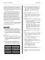
These instructions cover the model types listed in Table 1
below. Supplementary sheets are attached for units with special
options or features.
Table 1: A. Model Number Format :
350T-Input-Output-Mounting-Certification-Calibration
B. Typical Model Number: 350T-FQ1-Y-DIN-NCR-C
List of Drawings
Page
Electrical Connections: Frequency Input (4501-294)...........
6
Configuration Jumper Location: Frequency (45017
295).......
Dimensions: DIN Rail Mounting (4501-252)........................
8
Electrical Connections: Power Supply (4501-254)............... 8
Series
350T
Input
-FQ1
Output
-Y
-V0
-V5
Mtg.
-DIN
Cert.
-NCR
Calib.
Blank
-C
Notes (Table 1):
1. The FQ1 can be ordered with or without the factory calibration
("-C") option. Any customer-specified calibration information
will be included on a separate calibration label on the unit.
2. Consult the factory for current information on agency (e.g.
Canadian Standards Association, etc.) approvals.
IMPORTANT SAFETY CONSIDERATIONS
DESCRIPTION:
It is very important for the user to consider the possible adverse
effects of power, wiring, component, sensor, or software failures in designing any type of control or monitoring system. This is
especially important where economic property loss or human life is
involved. It is important that the user employ satisfactory overall
system design. It is agreed between the Buyer and Acromag, that
this is the Buyer's responsibility.
ACROMAG, INCORPORATED
30765 South Wixom Road
PO Box 437
Wixom, MI 48393-7037, USA
These DC-powered transmitters accept a periodic or pulse
waveform signal, such as those originating from tachometers,
magnetic transducers, and turbine flow meters, and convert this
signal to a process current or voltage output directly proportional to
the signal frequency. The input circuit is direct-coupled and can
accept signal amplitudes from ±25mV to 150V RMS. Input circuit
isolation is standard and wide-range zero and span adjustments are
included. Any one of ten input frequency ranges, from 25 to
25600Hz spans, can be selected by changing one jumper (shunt
block) on a digital divider network. These transmitters are RFI and
EMI protected, operate over large temperature ranges, and feature
excellent temperature coefficients, which minimize the effects from
the harsh plant environment.
The 350T Series is a DIN-rail mounted transmitter family
designed to be used as a functional component to provide the user
with a modular approach to the varied applications in the field. The
Series 350T complements the Acromag Series 250T two-wire
transmitter line, providing the same input conditioning for three-wire
applications. That is, Series 350T transmitters require a separate
power supply connection, while the output signal and DC power
share a common lead. The small package size, low power
requirements, and wide supply range offers maximum flexibility to
the system designer. As a three-wire DC-powered device, it can
also be used in critical applications that require the use of redundant
supplies. The Series 350T includes reverse polarity protection,
current limiting, and operates from a single 10-36V DC supply. In
applications requiring only a single transmitter, the 350T can use
available DC power, or it can be wired to an optional Series 35PS
power supply module. The Series 35PS power supply module
receives it's power from either 115V or 230V AC.
Tel: (248) 624-1541
FAX: (248) 624-9234
Copyright 1995 Acromag, Inc., Printed in the USA.
Data and specifications are subject to change without notice.
8500-329-B95J003
-1-
Series 350T User's Manual
Frequency Input
___________________________________________________________________________________________
Isolation: The input circuit is electrically isolated from the output
and power circuits, allowing the input to operate at up to
250VAC, or 354V DC off ground, on a continuous basis (will
withstand 1500V AC dielectric strength test for one minute
without breakdown). This complies with test requirements
outlined in ANSI/ISA-S82.01-1988 for the voltage rating
specified.
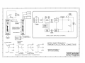
Applications requiring multiple transmitters at a single location can
more efficiently share a single DC supply. The modular approach of
this design and wide selection of companion Acromag flat-pack
modules allows additional transmitters, input modules, isolators, and
alarms to be easily integrated, as required. See Drawing 4501-294
for a simplified Series 350T schematic.
Additional features of this unit include the following. A quartz
crystal time-base design is used for improved temperature
performance. Three field-selectable filter network time constants
are provided to optimize the output response-time and ripple
characteristics. Two field-selectable input threshold circuits are
provided; one for bipolar (zero crossing) signals and one for
unipolar (non-zero crossing) signals. In the bipolar mode, the
transmitter has a zero volt threshold and fixed hysteresis. If
configured in the unipolar mode, the module has a 1.5 volt threshold
and fixed hysteresis. In addition, the unipolar mode provides an
excitation or pull-up circuit. This excitation allows interfacing to
passive frequency inputs, such as with "dry-rated" contact closure
and open collector transistor switching.
Input Circuit Open Response: Down-scale drive standard.
Bipolar Input Configuration: User configured by internal
jumpers(shunt blocks): Threshold: 0.0V DC; Input Amplitude:
±25mV to 150V RMS; Hysteresis: ±25mV fixed, nominal; The
switching points are -25mV and +25mV (nominal), or 0.0V
±0.025V.
Unipolar Input Configuration: User configured by internal shunt
jumper.
•
Threshold: 1.5V DC. Attenuator resistors may be installed
on the PC board to further reduce sensitivity by raising the
threshold level--consult the factory.
•
Hysteresis: ±25mV fixed, nominal. The switching points
are +1.525V and +1.475V (nominal), or +1.5V ±0.025V
•
Input Amplitude: 0 to 2V to 150V RMS.
•
Unipolar Excitation Supply: In the unipolar mode, the (L)
terminal provides an excitation supply for contact closure
or open collector transistor switching circuits. Nominal
excitation/pull-up is 5VDC through 15KΩ (0.333mA,
nominal).
NOTE: If input leads are long, capacitance developed
across the input leads could limit use to lower frequencies.
Input wiring is inserted in the bottom of the unit, while output and
power wiring is inserted at the top of the unit. Screws to secure the
wiring are located on the front panel. Connectors are screw-clamp
type and accept wire size up to14 AWG.
SPECIFICATIONS:
Function: This family of isolated, DC powered transmitters
accepts a frequency, periodic, or pulse waveform input signal,
provides input circuit isolation, and converts the input signal to a
process current or voltage output. The output and DC power
share a common terminal (3-Wire connection). Wide-range
zero and span adjustments utilize 22-turn potentiometers which
are accessible on front of the unit. The transmitter is DIN-rail
mounted.
Minimum Pulse Width: The minimum pulse width required is
10uS.
OUTPUT: Process Current or Voltage output. The output shares a
common with the power supply. Voltage outputs are designed
to provide true voltage out, with zero volts included, and to be
stable with capacitive loads.
MODEL/SERIES: 350T- (Color coded with a white label)
-Y : 4 to 20mA DC (see Load Resistance Range Equation)
-V0: 0 to 10V DC into 10,000 ohms or greater
-V5: 0 to 5V DC into 5,000 ohms or greater
INPUT: Frequency: direct-coupled input for span ranges from 25 to
25,600 Hz. The input impedance is 50KΩ typical. Input span
and zero ranges are adjustable as specified below, except for
special ranges which are factory calibrated per customer
specifications.
Load Resistance Range Equation (-Y output option): The
maximum load resistance for 20mA compliance is a function of
input supply voltage as follows:
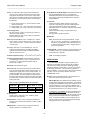
-FQ1: Frequency: Span 25Hz to 25,600Hz, Zero: 0 to 20% of
Span. The input span is continuously adjustable over the
preselected input span range. The minimum input frequency for
any range, can be from 0 to 20% of the full scale frequency.
FREQUENCY RANGE
Range A
Range B
Range C
Range D
Range E
Range F
Range G
Range H
Range I
Range J
R-Load (Maximum) = (Minimum VDC supply - 2.5V) / 0.02A
At 10.0V DC supply, R-Load = 0 to 375Ω
At 12.5V DC supply, R-Load = 0 to 500Ω
At 15.0V DC supply, R-Load = 0 to 625Ω
At 24.0V DC supply, R-Load = 0 to 1075Ω
SPAN RANGE
25 to
50 Hz
50 to
100 Hz
100 to
200 Hz
200 to
400 Hz
400 to
800 Hz
800 to
1,600 Hz
1,600 to
3,200 Hz
3,200 to
6,400 Hz
6,400 to
12,800 Hz
12,800 to
25,600 Hz
Output Limiting: Voltage units: 150% of full scale output, nominal;
Current units; 125% of full-scale output, nominal.
Output Ripple: Less than +/-0.1% of the maximum output span for
inputs from 10-100% of full-scale when recommended filter is
selected.
-2-
Series 350T User's Manual
Frequency Input
___________________________________________________________________________________________
Power: An external DC power supply is required between the
output (P) and (-) terminals. Transmitter current is for rated
supply inputs, full-scale output, and no load on voltage output
units. Diode on transmitter provides reverse polarity protection.
CAUTION: Do not exceed 36V DC peak, to avoid damage to
the transmitter.
Surge Withstand Capability (SWC): Input/Output terminations are
rated per ANSI/IEEE C37.90-1978. Unit is tested to a
standardized test waveform that is representative of surges
(high frequency transient electricalinterference), observed in
actual installations.
Construction:
Printed Circuit Boards: Military grade FR-4 epoxy glass.
Terminals: Compression type, wire size 14 AWG maximum.
Case: Self-extinguishing NYLON Type 6.6 polyamide
thermoplastic UL94 V-2, color-black. General Purpose, NEMA
Type 1 enclosure.
Printed Circuit Board Coating: Fungus resistant acrylic
conformal coat.
Mounting Position: Position insensitive.
A. Process Current Output (-Y): +10.0V to 36.0V DC, 30mA
(35mA at current limit).
B. Voltage Output (-V0): +12.5V to 36.0V DC, 9mA maximum.
C. Voltage Output (-V5): +10.0V to 36.0V DC, 9mA maximum.
Power Supply Effect:
DC Volts: less than ±0.001% of output span per volt DC, for
rated power supply variations.
60/120 Hz ripple: less than ±0.01% of span per volt peak-topeak of power supply ripple.
MOUNTING:
Reference Test Conditions: Input: 0-12800Hz, 100Ω resistive
source; Output (-Y units): 4-20mA DC (500Ω load); Output (-Vx
units): 0-10V DC into 10KΩ or greater; Ambient 77oF (25oC);
+15V DC supply.
-DIN: General Purpose Housing, DIN Rail-Mount - accepts
both "G" & "T" rails. "G" Rail (32mm), Type EN50035; "T"
Rail (35mm), Type EN50022. Refer to Drawing 4501-540
for outline and clearance dimensions. Shipping Weight: 1
pound (0.45 Kg) packed.
Accuracy: Better than ±0.1% of calibrated span. The error
includes the combined effects of transmitter repeatability,
hysteresis, terminal point linearity and adjustment resolution.
Does not include sensor error.
CERTIFICATION: Consult the factory for current information on the
availability of agency (e.g. Canadian Standards Association,
Factory Mutual, etc.) approvals.
Ambient Temperature Range: -13oF to 185oF (-25oC to 85oC).
-NCR: No Certification Required.
Ambient Temperature Effect: (Combined effects of zero/span
over temperature) Less than ± 0.01 % of output span per oF
(±0.018% per oC) over ambient temperature range for
reference test conditions.
INSTALLATION:
This transmitter is packaged in a general purpose type of
enclosure, use an auxiliary enclosure to protect the unit against
unfavorable environments and locations. Maximum operating
ambient temperatures should be within -13 to 185oF (-25 to 85oC)
for satisfactory performance. If the unit is factory calibrated, it is
ready for installation. Connect as shown in the Connection Drawing
4501-294. If the unit is not factory calibrated, refer to the
"CALIBRATION" section.
Bandwidth: -3dB at 25600 Hz, typical.
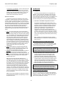
Response Time: The shunt-block selection of the filter networks
on the circuit board will result in different response times. The
standard unit is shipped with a 0.4 second response filter. To
maintain low output ripple, for each frequency range, use the
recommended filter. For a step change in the input frequency,
the nominal response time for a 98% change of the output span
is specified below. Install shunt blocks per Table below (refer to
Drawing 4501-295).
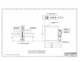
Mounting: Mount transmitter assembly - refer to Drawing 4501252 for mounting and clearance dimensions.
DIN Rail Mounting: Use suitable fastening hardware to secure
the DIN rail to the designated mounting surface. The transmitter
is supplied with the DIN Rail mounting option (-DIN) and can be
mounted to either the "T" or "G" style rails. Installation of the
alarm to the rail depends on the type of DIN rail used. Units can
be mounted side-by-side on 1.6 inch centers, if required.
Table: Frequency Range/Response Time Selection
RESPONSE
Frequency
Filter Jumpers
TIME (98%)
Span Range
Jumper Block: J1 (shunt)
8.0 seconds
A thru J
Pins 1 & 3
Pins 2 & 4
5.0 seconds
C thru J
Pins 3 & 5
Pins 2 & 4
0.4 seconds
D thru J
Pins 3 & 5
Pins 4 & 6
"T" Rail (35mm), Type EN50022: To attach a transmitter to this
style of DIN rail, angle the top of the unit towards the rail and
locate the top groove of the adapter over the upper lip of the rail.
Firmly push the unit towards the rail until it snaps solidly into
place. To remove a transmitter, insert a screwdriver into the
lower arm of the connector and pull downwards while applying
outward pressure to the bottom of the unit.
Noise Rejection:
Common Mode: 115dB, 60 Hz, 100Ω unbalance, typical.
Normal Mode: Not applicable.
RFI Resistance: Less than ±0.5% of output span with RFI field
strengths of up to 10V/meter at frequencies of 27MHz, 151MHz,
and 467MHz.
EMI Resistance: Less than ±0.25% of output span effect with
switching solenoids or commutator motors.
-3-
Series 350T User's Manual
Frequency Input
___________________________________________________________________________________________
CALIBRATION:
"G" Rail (32mm), Type EN50035: To attach a transmitter to this
style of DIN rail, angle the unit so that the upper groove of the
adapter hooks under the top lip of the rail. Firmly push the unit
towards the rail until it snaps solidly into place. To remove an
transmitter, pull the lower part of the unit outwards until it
releases from the rail and lift the unit from rail.
A. TRANSMITTER
This section provides information for unit configuration and
calibration. If the unit was factory calibrated, jumpers have been
placed in their proper positions and verification of the calibration
can be made per the Adjustment Procedure. If the calibration of the
unit is to be changed, first go to the "Shunt Block Configuration
Procedure" before going to the Transmitter Adjustment Procedure.
Electrical Connections:
The electrical connections are independent of the mounting
configuration. The wire size used to connect the unit to the control
system is not critical. All terminal strips can accommodate wire
from 14-26 AWG. Strip back wire insulation 1/4-inch on each lead
before installing it into the terminal block. Input wiring may be either
shielded or unshielded twisted pair. Output wires should be twisted
pair. Since common mode voltages can exist on signal wiring,
adequate wire insulation should be used and proper wiring
practices followed. It is recommended that output/power wiring be
separated from signal wiring for safety, as well as for low noise
pickup.
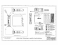
1. Transmitter - Shunt Block Configuration Procedure:
The frequency transmitter is quite universal in that it can be
configured for Unipolar or Bipolar input signals, a large number
of frequency ranges, and ripple/response filtering. Before the
adjustment procedure can proceed, the jumpers have to be
configured to the requirements of the application (refer to
Drawing 4501-295 for details). To gain access to the
Configuration Jumpers, first remove transmitter from the
installation. Second, remove the circuit boards from the plastic
enclosure as described in the Jumper Configuration procedure
below. Third, configure the jumpers (shunt blocks) as described
in the Jumper Configuration procedure below (refer to Drawing
4501-295).
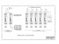
1. Power: Connect DC power supply per Connection Drawing
4501-294. These transmitters operate from DC power supplies
only. Power supply voltage is not critical and normally should be
from 10.0V to 36V DC. The supply voltage must not exceed 36
Volts, even instantaneously, and must be adequate to furnish
full-scale current or voltage to the load. Variations in power
supply voltage above the minimum required, or variations in
load resistance have negligible effect on transmitter accuracy.
Refer to "POWER" in the preceding SPECFICATIONS section
for current requirements. The minus (-) power supply lead and
the minus (-) output lead share a common terminal. This device
includes input current limiting and reverse polarity protection.
Refer to Drawing 4501-254 for other power supply
configurations.
2. Output: Connect output per Connection Drawing 4501-294.
Load range is a function of the module's output type; refer to
"Output" in the preceding "SPECIFICATIONS" section. The
output shares a common with the power supply.
3. Grounding: The General Purpose Housing of this transmitter is
plastic and does not require an earth ground connection.
4. Input: Connect the input per Connection Drawing 4501-294. Be
sure to observe proper polarity on unipolar inputs, see label for
input type. If unit is factory calibrated, the calibration label
indicates range of input.
Note: Calibration per the Adjustment Procedure should be
performed before the circuit boards are reassembled within the
plastic enclosure.
Disassembly Procedure for the 350T Plastic Housing:
The plastic housing has no screws, it "snaps" together. A flathead screwdriver (Acromag 5021-216 or equivalent) is needed to
pry the housing apart as described in the following steps.
CAUTION: Do not push the screwdriver blade into the housing
more than approximately 0.1 inches while prying it apart. Handling
of the printed circuit boards should only be done at a static-free
workstation, otherwise, damage to the electronics could result.
1. To begin disassembly (refer to Drawing 4501-295) place the
screwdriver at point A (left side of the transmitter). While
pressing the blade into the seam, use a twisting motion to
separate the sides slightly. Repeat this operation at point B.
2. Now that the two pieces have been partially separated, use the
screwdriver blade to work the left side of the package loose by
working around the transmitter and carefully prying the sides
further apart. Repeat this action until it is easy to remove the left
side from the plastic pins holding the pieces together.
3. Repeat this operation for the right side at points C and D.
Note: The input circuit is electrically isolated from the
output/power circuit, allowing the input to operate up to 250V
AC, or 354V DC off ground, on a continuous basis. If your input
is from a contact closure or from an open collector transistor,
the excitation circuit must be activated by placing a short jumper
wire between the input (+) and (L) terminal of the transmitter.
The input circuit of this transmitter accepts most periodic
waveforms and will trigger on the positive edge of the input
waveform. The input stage of this transmitter has a built-in lowpass filter (R1, C1) to remove any high frequency noise that may
be present on the input signal. If a digital 5V pulse is used to
drive the input stage, the width of the pulse should be greater
than 10 microseconds.
CAUTION: If the two PC boards become separated while taking
the package apart, re-align the boards making sure that both
interconnection headers are aligned with their mating sockets at
locations E & F and carefully push the boards back together.
Jumper Configuration (Shunt Blocks):
Shunt blocks are provided to accommodate in-field configuration
changes. In case of misplacement, additional shunt blocks may be
ordered from the factory. When ordering additional shunt blocks,
refer to Acromag Part Number 1004-332.
Note: If the input signal amplitude is not adequate to meet the
threshold/hysteresis requirements, the output will go to a value
that represents 0 Hertz.
-4-
Series 350T User's Manual
Frequency Input
___________________________________________________________________________________________
Transmitter - Calibration Example:
1. Input Conditioning Selection: Determine whether the input signal
is a zero crossing or a non-zero crossing signal. The sinusoidal
output from a passive magnetic pickup is a typical "zerocrossing" signal. A typical TTL output is a non-zero crossing
signal type. Refer to Drawing 4501-295 for proper jumper
(shunt) position.
2. Input Frequency Range: Select the desired frequency range for
the input signal and place the shunt block in the required range
position, A through J. Refer to Drawing 4501-295 for proper
jumper (shunt block) position. NOTE: for best results, select the
smallest frequency range that will cover the frequency span
being monitored.
3. Output Ripple/Response Time: Select the filter for desired
results. Refer to table 1 on Drawing 4501-295 for proper
jumper (shunt) position. Refer to "Response Time" in the
preceding "SPECIFICATIONS" section, which describes the
frequency/response-time combinations that can be achieved
while maintaining less than ±0.1% output ripple from 10 to
100% of full-scale. Faster response-times may be used when
output ripple is not critical. Units which have not been factory
calibrated have a response time of 0.4 seconds.
4. Important: Mark the Transmitter's Configuration on the
calibration label located on the enclosure.
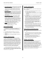
Example: IN: Bipolar, Range "I"; 0 to 12,800Hz
Filter - 3; 0.4 seconds.
Model : 350T-FQ1-Y-DIN-NCR
Input : 0-12800Hz, Bipolar input, Filter: 0.4 second step response.
Output: 4-20mA DC
1. The calibration signal amplitude requirements are a function of
the "Input Conditioning Type" selected.
A. Unipolar (Threshold: 1.5V DC Nominal), use a 0-2.0V signal
or greater.
B. Bipolar (Threshold: 0.0V DC Nominal), use a +/-0.2V signal
or greater.
2. Set the input frequency to 0 Hz. Adjust the Zero (Z) pot until the
output reads 4.000mA. If the output cannot be reduced to
4.000mA, turn the "Span" pot counter clockwise until the output
is reduced to the desired value. NOTE: If the minimum input is
0 Hz, it can be simulated by temporarily disconnecting the
signal generator and shorting the input terminals of the
transmitter. Before going to Step 3, remove the short circuit
and connect the signal generator to the input terminals.
3. Set the input frequency to 12,800 Hz. Adjust the Span (S) pot
until the output reads 20.000mA.
4. Repeat Steps 2 and 3 above until the readings converge. The
instrument is now calibrated. Several mid-point values should
also be checked to verify proper operation of the transmitter.
5. After the above calibration procedure is complete, install the
transmitter PC Board assembly back into its case as described
in the assembly procedure below.
Jumper Configuration Example:
The following is the configuration for the example given below,
make adjustments to the configuration as required for your
application. For our example, configure the internal jumpers as
follows:
Assembly Procedure for the 350T Plastic Housing:
Note: The Model/Serial Number label is attached to the left plastic
side.
A. Unipolar/Bipolar: Bipolar (Shunt Block J1, pins 9 & 10).
B. Frequency Range: Range I, 0 to 12800Hz (Shunt Block J2,
position I).
C. Ripple/Response: 0.4 Seconds (Shunt Block J1, pins 3 to 5
& 4 to 6).
1. Refer to drawing 4501-295 and line up the left plastic side with
the board and terminal assembly. Carefully but firmly press the
pieces together.
2. Before installing the right side, place the DIN rail mounting
bracket around the pins at the back of the housing.
3. Line up the right side of the housing with the assembly and
carefully but firmly press the pieces together.
Transmitter - Adjustment Procedure:
Connect transmitter as shown in the Connection Drawing
4501-294. The input signal source must be adjustable over the
entire frequency range (0-25600 Hz) of the transmitter. In addition,
the frequency source must be adjustable and stable to any specific
frequency with an accuracy of 0.1% or better. Signal amplitude
should be set at a level representative of the actual input signal. It is
recommended that a frequency counter be used to measure input
frequency, as most dial markings are not accurate enough. The
transmitter power supply voltage must be between 10 and 36V at
the terminals of the transmitter. The output voltage must be
measured to 0.1% accuracy or better for proper results.
GENERAL MAINTENANCE:
The transmitter contains solid-state components and requires no
maintenance except for periodic cleaning and calibration
verification. When a failure is suspected, a convenient method for
identifying a faulty transmitter is to exchange it with a known good
unit. It is highly recommended that a non-functioning transmitter be
returned to Acromag for repair, since Acromag makes use of tested
and burned-in parts, and in some cases, parts that have been
selected for characteristics beyond that specified by the
manufacturer. Further, Acromag has automated test equipment that
thoroughly checks the performance of each transmitter.
The Zero and Span adjustments are accessible on the front
panel of the transmitter, see Drawing 4501-294 for their location.
The screwdriver blade, used to adjust the potentiometers, should not
be more than 0.1 inch (2.54mm) wide.
-5-