1
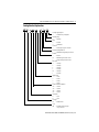
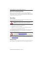
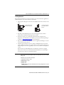
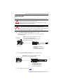
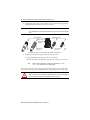
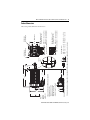
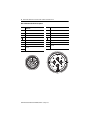
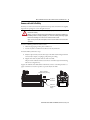
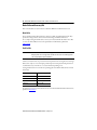
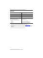
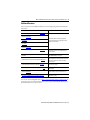
Installation Instructions
MP-Series Medium-inertia Servo Motor
with 115 mm to 215 mm Frame Size
Catalog Numbers MPM-A1151, MPM-A1152, MPM-A1153, MPM-A1302, MPM-A1304,
MPM-A1651, MPM-A1652, MPM-A1653, MPM-A2152, MPM-A2153, MPM-A2154,
MPM-B1151, MPM-B1152, MPM-B1153, MPM-B1302, MPM-B1304, MPM-B1651,
MPM-B1652, MPM-B1653, MPM-B2152, MPM-B2153, MPM-B2154
Topic
Page
Important User Information
2
Catalog Number Explanation
3
About the MP-Series Medium Inertia Motors
4
Before You Begin
4
Install the Motor
8
Product Dimensions
13
Motor Load Force Ratings
15
Connector Data
17
Remove and Install a Shaft Key
19
Motor Cables and Accessory Kits
20
Specifications
22
Additional Resources
23
2 MP-Series Medium-inertia Servo Motor with 115 mm to 215 mm Frame Size
Important User Information
Read this document and the documents listed in the additional resources section about installation, configuration, and operation of
this equipment before you install, configure, operate, or maintain this product. Users are required to familiarize themselves with
installation and wiring instructions in addition to requirements of all applicable codes, laws, and standards.
Activities including installation, adjustments, putting into service, use, assembly, disassembly, and maintenance are required to be
carried out by suitably trained personnel in accordance with applicable code of practice.
If this equipment is used in a manner not specified by the manufacturer, the protection provided by the equipment may be impaired.
In no event will Rockwell Automation, Inc. be responsible or liable for indirect or consequential damages resulting from the use or
application of this equipment.
The examples and diagrams in this manual are included solely for illustrative purposes. Because of the many variables and
requirements associated with any particular installation, Rockwell Automation, Inc. cannot assume responsibility or liability for actual
use based on the examples and diagrams.
No patent liability is assumed by Rockwell Automation, Inc. with respect to use of information, circuits, equipment, or software
described in this manual.
Reproduction of the contents of this manual, in whole or in part, without written permission of Rockwell Automation, Inc., is
prohibited.
Throughout this manual, when necessary, we use notes to make you aware of safety considerations.
WARNING: Identifies information about practices or circumstances that can cause an explosion in a hazardous
environment, which may lead to personal injury or death, property damage, or economic loss.
ATTENTION: Identifies information about practices or circumstances that can lead to personal injury or death,
property damage, or economic loss. Attentions help you identify a hazard, avoid a hazard, and recognize the
consequence.
IMPORTANT Identifies information that is critical for successful application and understanding of the product.
Labels may also be on or inside the equipment to provide specific precautions.
SHOCK HAZARD: Labels may be on or inside the equipment, for example, a drive or motor, to alert people that
dangerous voltage may be present.
BURN HAZARD: Labels may be on or inside the equipment, for example, a drive or motor, to alert people that
surfaces may reach dangerous temperatures.
ARC FLASH HAZARD: Labels may be on or inside the equipment, for example, a motor control center, to alert
people to potential Arc Flash. Arc Flash will cause severe injury or death. Wear proper Personal Protective
Equipment (PPE). Follow ALL Regulatory requirements for safe work practices and for Personal Protective
Equipment (PPE).
Rockwell Automation Publication MPM-IN001E-EN-P - January 2015
MP-Series Medium-inertia Servo Motor with 115 mm to 215 mm Frame Size 3
Catalog Number Explanation
MP M - x xxx x x - x J 7 x A A
Factory Designated Options
A
= Standard factory configuration
Mounting Flange
A
= IEC metric
Brake
2
= No brake
4
= 24V DC brake
Connectors
7
= Circular, right angle, 180° rotatable
Enclosure/Shaft Key/Shaft Seal
J
= IP65/IP67 housing/shaft key/no shaft seal
Feedback
2
= Resolver
M
= Multi-turn high-resolution encoder
S
= Single-turn high-resolution encoder
Base Speed
B
= 1300 rpm
C
= 1500 rpm
E
= 2250 rpm
F
= 3000 rpm
M
= 4500 rpm
T
= 6000 rpm
Magnet Stacks
1
= 1 stack
2
= 2 stacks
3
= 3 stacks
4
= 4 stacks
Frame Size- Bolt Circle Diameter
115 = 115 mm
130 = 130 mm
165 = 165 mm
215 = 215 mm
Voltage Class
A
= 200V
B
= 400V
Series Type
M
= Medium inertia
Series
Premium permanent magnet
MP
=
rotary servo motor
Rockwell Automation Publication MPM-IN001E-EN-P - January 2015
4 MP-Series Medium-inertia Servo Motor with 115 mm to 215 mm Frame Size
About the MP-Series Medium Inertia Motors
MP-Series™ medium-inertia (Bulletin MPM) motors feature resolvers and single-turn or
multi-turn high resolution encoders. They are also available with 24V DC holding brakes. These
compact brushless servo motors combine the features of the MP-Series low-inertia motors with a
rotor that is better suited for high-inertia loads.
Before You Begin
Remove all packing material from within and around the item. After unpacking, verify the
nameplate catalog number against the purchase order.
ATTENTION: To avoid personal injury and damage to the motor, do not lift or handle the motor by
the motor shaft. The cap on the shaft can come loose and cause you to drop the motor.
1. Remove the motor carefully from its shipping container.
2. Visually inspect the motor for any damage.
3. Examine the motor frame, front output shaft, and mounting pilot for any defects.
4. Notify the carrier of any shipping damage immediately.
Keep the original packing material in case you need to return the product for repair or transport
it to another location. Use both the inner and outer packing cartons to provide adequate
protection for a unit returned for service.
ATTENTION: Do not attempt to open or modify this motor beyond changing the connector
orientation as described in Change Connector Orientation on page 9.
Only an authorized Allen-Bradley repair center can service this item. Refer to Rockwell Automation
Support for assistance to locate the nearest repair center.
Store or operate your motor in a clean and dry location within the environmental conditions
listed in Specifications on page 22.
Removing the Shaft Cap
Use your hand to remove the protective cap that is installed on the motor shaft or pry off the cap
with a screwdriver. Do not use a hammer or other tools as they can damage the motor shaft.
Rockwell Automation Publication MPM-IN001E-EN-P - January 2015
MP-Series Medium-inertia Servo Motor with 115 mm to 215 mm Frame Size 5
To Prolong Motor Life
Proper design and maintenance can increase the life of a servo motor. Follow these guidelines to
maximize the life of a servo motor within your environment:
• Always provide a drip loop in each cable to carry liquids away from the connection to the
motor.
The cable enters beneath the
motor and forms a drip loop.
The cable enters above the
motor and does not form a
drip loop.
• If possible, provide shields that protect the motor housing, shaft seals, and their
junctions from contamination by foreign matter or fluids.
• Shaft seals are subject to wear and require periodic inspection and replacement.
Replacement is recommended every 3 months, not to exceed 12 months, depending on
use. Refer to Shaft Seal Kits on page 20 for more information.
• Inspect the motor and seals for damage or wear on a regular basis. If damage or excessive
wear is observed, replace the item.
• The brake option on this servo motor is a spring-set holding brake that releases when
voltage is applied to the brake coil. A separate power source is required to disengage the
brake. This power source can be applied by a servo motor controller or manual operator
control.
If system main power fails, holding brakes can withstand occasional use as stopping
brakes. However, this creates rotational mechanical backlash that can cause damage to
the system, increase brake wear, and reduce brake life.
IMPORTANT Holding brakes are not designed to stop rotation of the motor shaft, and they are not intended to be
used as a safety device. They are designed to hold a motor shaft at 0 rpm for up to the rated brake
holding torque.
Follow these steps to prevent motor shaft rotation.
1.
2.
3.
4.
Command the servo drive to 0 rpm.
Verify the motor is at 0 rpm.
Engage the brake.
Disable the drive.
Disabling the drive removes the potential for brake wear caused by a badly-tuned servo system
oscillating the shaft.
Rockwell Automation Publication MPM-IN001E-EN-P - January 2015
6 MP-Series Medium-inertia Servo Motor with 115 mm to 215 mm Frame Size
Using Shaft Seals
An additional seal is required on the motor shaft near the motor front bearing, if the shaft is
exposed to fluids or significant amounts of fine dust. This includes lubricating oil from a
gearbox. An IP65 or IP67 rating for the motor requires the use of a shaft seal and
environmentally sealed connectors/cables. The additional seal is not recommended in
applications where the motor shaft area is free of liquids or fine dust, and a lower rating is
sufficient:
• Refer to Specifications on page 22 for a brief description of the IP rating for these
MP-Series motors.
• Refer to Shaft Seal Kits on page 20 to find the catalog numbers of seal kits available for
your motor.
• Refer to Kinetix® Motion Accessories Specifications, publication GMC-TD004, to find
environmentally sealed connectors and cables compatible with the MP-Series motors.
Using Couplings and Pulleys
Mechanical connections to the motor shaft, such as couplings and pulleys, require a torsionally
rigid coupling or a reinforced timing belt. The high dynamic performance of servo motors can
cause couplings, pulleys, or belts to loosen or slip over time. A loose or slipping connection can
cause system instability and damage the motor shaft. All connections between the system and the
servo motor shaft must be rigid to achieve acceptable response from the system. Periodically
inspect connections to verify their rigidity.
When mounting couplings or pulleys to the motor shaft, be sure that the connections are
properly aligned and that axial and radial loads are within the specifications of the motor. Refer
to Shaft Seal Kits on page 20 for guidelines to achieve 20,000 hours of motor bearing life.
ATTENTION: Damage can occur to the motor bearings and the feedback device if sharp impact to
the shaft is applied during installation of couplings and pulleys. Damage to the feedback device can
result by applying leverage from the motor mounting face to remove devices mounted on the
motor shaft.
Do not strike the shaft, couplings, or pulleys with tools during installation or removal. Use a wheel
puller applying pressure from the user end of the shaft to remove any friction-fit or stuck device
from the motor shaft.
Preventing Electrical Noise
Electromagnetic interference (EMI), commonly called noise, can adversely impact motor
performance by inducing stray signals.
Follow these guidelines to prevent the effects of EMI:
• Isolate the power transformers, or install line filters on all AC input power lines.
• Separate signal cables from motor cabling and power wiring. Do not route signal cables
with motor and power wires, or over the vent openings of servo drives.
Rockwell Automation Publication MPM-IN001E-EN-P - January 2015
MP-Series Medium-inertia Servo Motor with 115 mm to 215 mm Frame Size 7
• Ground all equipment by using a single-point parallel ground system that employs
ground bus bars or large straps. If necessary, use additional electrical noise reduction
techniques to reduce EMI in noisy environments.
Refer to System Design for Control of Electrical Noise Reference Manual, publication
GMC-RM001, for additional information on reducing the effects of EMI by improving the
system level electromagnetic compatibility (EMC).
Build and Install the Cables
Correct cable routing and careful cable construction improves system electromagnetic
compatibility (EMC).
Follow these guidelines to build and install the cables:
• Keep the wire lengths as short as possible.
• Route noise sensitive wiring (encoder, serial, and I/O) away from input power and motor
power wiring.
• Separate cables by 0.3 m (1 ft) minimum for every 9 m (30 ft) of parallel run.
• Ground both ends of the encoder cable shield and twist the signal wire pairs to prevent
EMI from other equipment.
ATTENTION: High voltage can be present on the shield of a power cable, if the shield is not
grounded.
Verify that there is a connection to ground for any power cable shield.
ATTENTION: MP-Series motors produce leakage current in the protective earthing conductor that
exceeds 3.5 mA AC and/or 10 mA DC.
Be sure to properly ground the motor cables per the drive installation instructions.
Rockwell Automation Publication MPM-IN001E-EN-P - January 2015
8 MP-Series Medium-inertia Servo Motor with 115 mm to 215 mm Frame Size
Ground Shielded Signal Wires within a Power Cable
Always connect the shield on any signal wire pair routed inside a power cable to the overall
machine ground. If you are installing a 2090-CPBM7DF-xxAAxx or 2090-XXNPMF-xxSxx
power cable, loop the signal wire pair to the overall cable shield as shown in Grounding of Signal
Wire Shields in a Power Cable on page 8. Then clamp all of the shields together in the
power-cable (chassis) ground connection on the drive.
Grounding of Signal Wire Shields in a Power Cable
Factory Supplied
Shielded Signal Wires (one pair shown) within Power Cable
Overall Power Cable Shield
Field Modified
Signal Wire Shield Contacts Overall Power Cable Shield
All power and signal wire shields must connect to machine
ground.
Connect all signal wire shields and the overall power-cable shield to machine ground:
• The 2090-CPBM7DF-xxAFxx cable (shown) contains one signal wire pair.
• The 2090-XXNPMF-xxSxx cable contains two signal wire pairs.
The signal wire pairs within a power cable often carry a 24V DC brake signal, but can also carry
logic signals. Grounding the shield that surrounds the signal wires dissipates an induced voltage
and reduces the effects of EMI.
Install the Motor
MP-Series motors include a mounting pilot for aligning the motor on the machine. Preferred
fasteners are hardened steel. The installation must comply with all local regulations and use
equipment and installation practices that promote safety and electromagnetic compatibility.
ATTENTION: Unmounted motors, disconnected mechanical couplings, loose shaft keys, and
disconnected cables are dangerous if power is applied.
Lock-out and tag-out disassembled equipment (restrict electrical power).
Before applying power to the motor, remove the shaft key and other mechanical couplings that can
be thrown from the shaft.
ATTENTION: Make sure that cables are installed and restrained to prevent uneven tension or
flexing at the cable connections.
Excessive and uneven lateral force on the cable can inhibit environmental sealing as the cable
flexes.
Rockwell Automation Publication MPM-IN001E-EN-P - January 2015
MP-Series Medium-inertia Servo Motor with 115 mm to 215 mm Frame Size 9
Change Connector Orientation
You can rotate the connector housing up to 180°. This lets you adjust the connector to a position
that best protects the connection from possible environmental contaminates while providing
cable access.
ATTENTION: Connectors are designed to be rotated into a fixed position during motor installation,
and remain in that position without further adjustment. Do not rotate the connector multiple
times, and do not use tools or excessive force to rotate the connector. Excessive rotation or force can
damage the connector seal and reduce the international protection (IP) rating of the motor as
outlined in Specifications on page 22.
The circular DIN connector housing can be rotated up to 180° in either direction.
Follow these steps to rotate a DIN connector.
1. Mount and fully seat a mating cable on either the feedback or power/brake connector.
2. Grasp the mated connector and cable plug with your hands and slowly rotate them to the
outside of the motor.
ATTENTION: Apply force to only the motor connector and cable plug. Do not apply force
to the cable extending from the cable plug. Do not use tools (for example, pliers and
vise-grips) to rotate the connector.
3. Repeat these steps for the other connector.
Mount the Motor
Follow these steps to mount the motor.
ATTENTION: Damage can occur to the motor bearings and the feedback device if sharp impact to
the shaft is applied during installation of couplings and pulleys.
Do not strike the shaft, couplings, or pulleys with tools during installation or removal.
1. Provide sufficient clearance, heatsink mass, and cooling air so the motor stays within the
operating temperature range of 0…40 °C (32…104 °F).
Do not enclose the motor unless cooling air is forced across the motor, and keep other
heat producing devices away from the motor. Heatsink requirements are listed in a
footnote to the Specifications on page 22.
ATTENTION: Outer surfaces of the motor can reach high temperatures of 125 °C (275 °F)
during operation.
Take precautions to prevent accidental contact with hot surfaces. Consider motor surface
temperature when selecting connections and cables to install on a motor.
2. Verify the axial and radial shaft loads of your application do not exceed those listed in the
Motor Load Force Ratings on page 15.
3. Position the motor on the machine with its connectors pointing downward.
Rockwell Automation Publication MPM-IN001E-EN-P - January 2015
10 MP-Series Medium-inertia Servo Motor with 115 mm to 215 mm Frame Size
4. Insert and hand-tighten the fasteners in each of the four mounting holes in the motor
faceplate.
The mounting hole diameter is specified in the Product Dimensions on page 13 table.
5. Align the motor on the machine by using the mounting pilot hole to verify the correct
alignment.
6. Tighten the fasteners within the recommended torque range.
Cat. No.
Torque Range
MPM-x115x
0.8…1.0 N•m (7…9 lb•in)
MPM-x130x
MPM-x165x
4…10 N•m (35…90 lb•in)
MPM-x215x
8…20 N•m (70…180 lb•in)
7. Rotate the shaft to verify for electrical phasing and encoder alignment.
The index pulse occurs on a single-turn encoder when the shaft key is aligned with the
connectors. Refer to Product Dimensions on page 13 for a visual reference of this
alignment.
Rockwell Automation Publication MPM-IN001E-EN-P - January 2015
MP-Series Medium-inertia Servo Motor with 115 mm to 215 mm Frame Size 11
Attach the Motor Cables
Follow these steps to attach the feedback and power/brake cables after the motor is mounted.
ATTENTION: Servo drive power must be turned off before connecting or disconnecting the cables to
the motor, and if a cable is left disconnected at the motor end.
Arcing or unexpected motion can occur if the feedback, power, or brake cables are connected or
disconnected while power is applied to the servo drive.
ATTENTION: Be sure that cables are installed and restrained to prevent uneven tension or flexing at
the cable connectors. Provide support at 3 m (10 ft) intervals throughout the cable run.
Excessive and uneven lateral force at the cable connectors can result in the connector’s environmental
seal opening and closing as the cable flexes, or wires separating at the cable gland.
1. For the Threaded DIN (M4) Cable Plugs, install the O-rings.
An O-ring on the feedback connector is necessary to achieve the maximum
environmental rating.
Groove Reserved
for Cable Plug
Install the O-ring on the SpeedTec-ready DIN motor connector when
you are using the threaded DIN (M4) cable plugs.
Verify that the O-ring is not damaged, not twisted, and rests in the
groove near the rear of the connector.
SpeedTec-ready DIN
Motor Connector
Threaded DIN (M4) Cable Plug
• 2090-XXNxMF-Sxx standard feedback
and power cables
• 2090-CxxM4DF-xxAFxx continuous-flex
feedback, power, and power/brake cables
2. For the SpeedTec DIN (M7) Cable Plugs, do not install the O-rings.
Do not install the O-ring on the SpeedTec-ready DIN motor connector
when you are using the SpeedTec DIN (M7) cable plugs.
SpeedTec-ready DIN
Motor Connectors
SpeedTec DIN (M7) Cable Plug
• 2090-CFBM7Dx-xxAxxx standard and
continuous-flex feedback cables
• 2090-CPxM7DF-xxAxxx standard and
continuous-flex power/brake cables
3. Form a drip loop in the cable (see page 5).
Rockwell Automation Publication MPM-IN001E-EN-P - January 2015
12 MP-Series Medium-inertia Servo Motor with 115 mm to 215 mm Frame Size
4. Carefully align the flat surface on the feedback or the power/brake cable plug (shown in
the diagram) with the flat surface on the motor connector.
IMPORTANT The motor orientation shown is used to clearly show the alignment marker on each cable socket.
The recommended motor orientation when installed positions the connectors at the bottom of the
motor.
Power Plug Options
Feedback Plug Options
Top of connector is
relative to motor
orientation.
Tab on
Side
Flat Surface with
Logo on Top
Flat Surface with
Logo on Top
Tab on
Top
Connector plugs have either a tab or a flat surface with a logo to indicate the alignment point.
5. Hand tighten the collar on the plug to fully seat it on the connector:
• Threaded DIN (M4) cable plugs require five to six revolutions.
• SpeedTec DIN (M7) cable plugs require approximately one-quarter of a revolution.
TIP
A fully-seated threaded plug leaves a small opening, approximately 1…4 mm
(0.04…0.16 in.), between the connector and the plug.
Do not apply excessive force when mating the cable plug with the motor connector. If the plug
and connector do not go together with light hand force, realign the flat surfaces and try again.
ATTENTION: Align the keyed connectors and hand-tighten the recommended number of turns.
If you cannot tighten the connectors by hand, verify that the keyed connectors are properly aligned.
Do not use tools (for example, pliers and vise-grips) to tighten the connectors.
Rockwell Automation Publication MPM-IN001E-EN-P - January 2015
AD
LD
L
LE
LD
LE
L-LB
LA
T1
D
GE
T2
N2
Flush to
Pilot
M23 Power/Brake Connector(1)
is standard on these motors.
N2 N1 Pilot Diameters
Shaft End Hole
Thread and Depth
MPM-x115 = 6 x 6 x 25 MPM-x165 = 8 x 7 x 40
F MPM-x130 = 8 x 7 x 32 MPM-x215 = 10 x 9 x 59
Shaft Key Dimensions
MPM-x215 = 93.9 mm (3.69 in.)
MPM-x165x not listed above = 71.2 mm (2.80 in.)
M40 Power/Brake Connector(1)
is standard on these motors.
MPM-x115 = 67.7 mm (2.66 in.)
MPM-x130 = 67.7 mm (2.66 in.)
MPM-B165xC and MPM-B1651F = 68.2 mm (2.68 in.)
P
S (hole diameter)
M (bolt circle diameter)
(1) Electronic zero (index pulse or Stegmann ABS = 0) occurs when the shaft key or dimple (not shown) is aligned with the connectors (as shown).
M40 Feedback Connector shown for comparison.
HD AD
Changes to the dimensions for MPM-x165 motors with a M40
Power/Brake Connector are:
- Add 23.0 mm (0.91 in.) to AD
- Add 22.9 mm (0.90 in.) to HD
- Add 1.7 mm (0.07 in.) to LD
- Subtract 29.2 mm (1.15 in.) from LE
Recessed
End Cap on
MPM-x165
and MPM-x215
HD
LB
MP-Series Medium-inertia Servo Motor with 115 mm to 215 mm Frame Size 13
Product Dimensions
This section provides dimensions for the motors.
Rockwell Automation Publication MPM-IN001E-EN-P - January 2015
Rockwell Automation Publication MPM-IN001E-EN-P - January 2015
154.0
(6.06)
38.0
(1.496)
246.5
(9.70)
456.2
(17.96)
405.4
(15.96)
80.0
(3.149)
17.8
(0.70)
376.2
(14.81)
325.4
(12.81)
336.0
(13.23)
285.2
(11.23)
Refer to Kinetix Rotary Motion Specifications Technical Data, publication GMC-TD001, for pilot and shaft tolerances.
(1) See the diagram for dimension changes to MPM-x165x motors with an M40 power connector.
(2) For motors with a brake (MPM-xxxxxx-xxx4xx), adjust dimensions with these values:
MPM-x115 motors add 48.5 mm (1.91 in.) to L, LB, LD, and LE.
MPM-x130 motors add 48.5 mm (1.91 in.) to L, LB, LD, and LE.
MPM-x165 motors add 51.5 mm (2.03 in.) to L, LB, LD, and LE.
MPM-x215 motors add 88.9 mm (3.50 in.) to L, LB, LD. and LE.
MPM-A/B2154
MPM-A/B2153
234.4
(9.23)
274.6
(10.81)
354.6
(13.96)
251.0
(9.88)
MPM-A/B2152
14.0
(0.55)
277.4
(10.92)
60.0
(2.362)
337.4
(13.28)
301.8
(11.88)
185.2
(7.29)
328.2
(12.92)
28.0
(1.102)
388.2
(15.28)
113.4
(4.47)
200.2
(7.88)
226.6
(8.92)
286.6
(11.28)
MPM-A/B1653
MPM-A/B1652
MPM-A/B1651
MPM-A/B1304
203.7
(8.02)
12.19
(0.48)
229.4
(9.03)
279.4
(11.0)
50.0
(1.969)
152.9
(6.02)
155.4
(6.12)
178.6
(7.03)
24.0
(0.945)
228.6
(9.0)
98.6
(3.88)
MPM-A/B1302
149.6
(5.89)
175.3
(6.90)
10.16
(0.40)
215.3
(8.48)
40.0
(1.575)
124.2
(4.89)
149.9
(5.90)
189.9
(7.48)
LA
mm
(in.)
LD (1), (2)
mm
(in.)
L-LB (3)
mm
(in.)
LB (2)
mm
(in.)
L (2)
mm
(in.)
175.0
(6.89)
140.1
(5.52)
HD (1)
mm
(in.)
200.7
(7.90)
19.0
(0.748)
D
mm
(in.)
240.7
(9.48)
90.9
(3.58)
AD (1)
mm
(in.)
MPM-A/B1153
MPM-A/B1152
MPM-A/B1151
Motor Cat. No.
Dimensions
(3)
(4)
(5)
(6)
215.0
(8.465)
165.0
(6.496)
130.0
(5.118)
115.0
(4.528)
M
mm
(in.)
180.0
(7.09)
130.0
(5.12)
110.0
(4.33)
95.0
(3.74)
N1
mm
(in.)
108.0
(4.25)
81.0
(3.19)
70.3
(2.77)
59.0
(2.32)
N2
mm
(in.)
184.9
(7.28)
143.5
(5.65)
113.7
(4.48)
98.3
(3.87)
P
mm
(in.)
14.50
(0.571)
12.0
(0.481)
10.0
(0.401)
10.0
(0.401)
S (4)
mm
(in.)
3.73
(0.147)
3.12
(0.123)
2.74
(0.108)
2.74
(0.108)
T1
mm
(in.)
3.86
(0.152)
3.38
(0.133)
3.38
(0.133)
2.87
(0.113)
T2
mm
(in.)
10.0
(0.394)
8.0
(0.315)
8.0
(0.315)
6.0
(0.236)
F (5)
mm
(in.)
5.0
(0.197)
4.0
(0.158)
4.0
(0.158)
3.5
(0.138)
GE (6)
mm
(in.)
M12 x 1.75 - 6
H x 28 (1.10)
M10 x 1.5 - 6H
x 22 (0.87)
M8 x 1.25 - 6H
x 19 (0.75)
M6 x 1.0 - 6H
x 16 (0.63)
End of Shaft
Thread and
Depth of Hole
Tolerance is ±0.7 (±0.028).
Tolerance is +0.36 (±0.007) for MPM-x115 and MPM-x130 motors, and +0.43 (±0.008) for MPM-x165 and MPM-x215.
Tolerance is -0.03 (-0.001).
Tolerance is -0.1 (-0.004) for MPM-x115x, -0.2 (-0.007) for MPM-x130x and MPM-x165x, and -0.2 (-0.008) for MPM-x215x.
264.9
(10.43)
214.1
(8.43)
163.3
(6.43)
261.6
(10.30)
210.8
(8.30)
160.0
(6.30)
163.6
(6.44)
112.8
(4.44)
134.9
(5.31)
109.5
(4.31)
84.1
(3.31)
LE (1), (2)
mm
(in.)
14 MP-Series Medium-inertia Servo Motor with 115 mm to 215 mm Frame Size
MP-Series Medium-inertia Servo Motor with 115 mm to 215 mm Frame Size 15
Motor Load Force Ratings
Motors are capable of operating with a sustained shaft load. The load force locations are shown
in the figure and maximum values are in the tables.
Loads are measured in kilograms; pounds are mathematical conversions.
Load Forces on Shaft
Radial load force applied at center of shaft extension.
Axial Load Force
The tables represent 20,000 hour L10 bearing fatigue life at various loads and speeds. This 20,000
hour life does not account for possible application-specific life reduction that can occur due to
bearing grease contamination from external sources.
Radial Load Force Ratings
Motor Cat. No.
1000 rpm
kg (lb)
2000 rpm
3000 rpm
5000 rpm
kg (lb)
kg (lb)
kg (lb)
7000 rpm
kg (lb)
MPM-A/B1151
77 (170)
61 (134)
54 (119)
45 (99)
40 (88)
MPM-A/B1152
84 (185)
66 (145)
58 (128)
49 (108)
43 (95)
MPM-A/B1153
88 (194)
70 (154)
61 (134)
51 (112)
46 (101)
MPM-A/B1302
105 (231)
83 (183)
72 (159)
61 (134)
54 (119)
MPM-A/B1304
115 (253)
91 (200)
80 (176)
67 (148)
—
MPM-A/B1651
141 (311)
112 (247)
97 (214)
82 (181)
—
MPM-A/B1652
151 (333)
119 (262)
104 (229)
—
—
MPM-A/B1653
156 (344)
123 (271)
107 (236)
—
—
MPM-A/B2152
216 (476)
171 (377)
149 (328)
—
—
MPM-A/B2153
228 (502)
180 (396)
156 (344)
—
—
MPM-A/B2154
235 (518)
185 (407)
161 (355)
—
—
Rockwell Automation Publication MPM-IN001E-EN-P - January 2015
16 MP-Series Medium-inertia Servo Motor with 115 mm to 215 mm Frame Size
Axial Load Force Ratings (maximum radial load)
Motor Cat. No.
1000 rpm
2000 rpm
3000 rpm
5000 rpm
7000 rpm
MPM-A/B
kg (lb)
kg (lb)
kg (lb)
kg (lb)
kg (lb)
MPM-A/B1151
29 (64)
22 (48)
18 (40)
14 (31)
12 (26)
MPM-A/B1152
31 (68)
23 (51)
19 (42)
15 (33)
13 (29)
MPM-A/B1153
33 (73)
24 (53)
20 (44)
16 (35)
14 (31)
MPM-A/B1302
26 (57)
19 (42)
16 (35)
13 (29)
11 (24)
MPM-A/B1304
30 (66)
22 (48)
18 (40)
15 (33)
—
MPM-A/B1651
37 (81)
28 (62)
23 (51)
18 (40)
—
MPM-A/B1652
41 (90)
30 (66)
25 (55)
—
—
MPM-A/B1653
43 (95)
32 (70)
27 (59)
—
—
MPM-A/B2152
55 (121)
40 (88)
34 (75)
—
—
MPM-A/B2153
60 (132)
44 (97)
36 (79)
—
—
MPM-A/B2154
63 (139)
46 (101)
38 (84)
—
—
Axial Load Force Ratings (zero radial load)
Motor Cat. No.
1000 rpm
2000 rpm
3000 rpm
5000 rpm
7000 rpm
MPM-A/B
kg (lb)
kg (lb)
kg (lb)
kg (lb)
kg (lb)
MPM-A/B1151
46 (101)
34 (75)
28 (62)
23 (51)
19 (42)
MPM-A/B1152
46 (101)
34 (75)
28 (62)
23 (51)
19 (42)
MPM-A/B1153
46 (101)
34 (75)
28 (62)
23 (51)
19 (42)
MPM-A/B1302
46 (101)
34 (75)
28 (62)
23 (51)
19 (42)
MPM-A/B1304
46 (101)
34 (75)
28 (62)
23 (51)
—
MPM-A/B1651
61 (134)
44 (97)
38 (84)
30 (66)
—
MPM-A/B1652
61 (134)
44 (97)
38 (84)
—
—
MPM-A/B1653
61 (134)
44 (97)
38 (84)
—
—
MPM-A/B2152
90 (198)
65 (143)
54 (119)
—
—
MPM-A/B2153
90 (198)
65 (143)
54 (119)
—
—
MPM-A/B2154
90 (198)
65 (143)
54 (119)
—
—
Rockwell Automation Publication MPM-IN001E-EN-P - January 2015
MP-Series Medium-inertia Servo Motor with 115 mm to 215 mm Frame Size 17
Connector Data
These tables provide the signal descriptions for the feedback, power, and brake pinouts on the
connectors.
M23 Feedback Pin Descriptions
Pin
MPM-A115x and MPM-A130x,
(230V) Motors with
5V High-resolution Encoder
MPM-A165x or MPM-A215x
(230V), and MPM-Bxxxx (460V)
Motors with
9V High-resolution Encoder
MPM-Axxxx (230V) or
MPM-Bxxxx (460V) Motors with
4-pole Resolver
1
SIN+
SIN+
S2
2
SIN-
SIN-
S4
3
Cos+
COS+
S1
4
Cos-
Cos-
S3
5
DATA+
DATA+
R1
6
DATA-
DATA-
R2
7
Reserved
8
Reserved
9
EPWR_5V
10
ECOM
Reserved
11
EPWR_9V
Reserved
12
ECOM
13
TS+
TS+
TS+
14
TS-
TS-
TS-
Reserved
Reserved
Reserved
15
16
17
M23 Feedback Connector
11
10
16
9
8
1
12
2
3
13
17
4
14
15
5
7 6
Rockwell Automation Publication MPM-IN001E-EN-P - January 2015
18 MP-Series Medium-inertia Servo Motor with 115 mm to 215 mm Frame Size
M23 and M40 Power/Brake Pin Descriptions
Pin
MPM-x115x, MPM-x130x, MPM-x165x,
MPM-x215x
Pin
MPM-x165x, MPM-x215x
A
Phase U
U
Phase U
B
Phase V
V
Phase V
Phase W
W
C
Ground
Phase W
Ground
E
Reserved
+
BR+
F
BR+
-
BR-
G
BR-
1
Reserved
H
2
Reserved
L
M40 Power/Brake Connector
M23 Power/Brake Connector
B
C
W
G
F
A
E
H
-
L
Rockwell Automation Publication MPM-IN001E-EN-P - January 2015
2
V
+
U
1
MP-Series Medium-inertia Servo Motor with 115 mm to 215 mm Frame Size 19
Remove and Install a Shaft Key
Shaft keys are constructed of steel. The specified tolerance provides an interference fit (slightly
larger than the opening) for a secure and rigid connection.
ATTENTION: Do not strike the motor’s shaft, couplings, or pulleys with tools during installation or
removal of the shaft key.
Damage can occur to the motor bearings and the feedback device if a sharp impact is applied to the
shaft during installation of couplings and pulleys, or to remove the shaft key, or if leverage is applied
from the motor mounting face to remove devices mounted on the motor shaft.
Apply a constant pressure, with a wheel puller, to the user end of the shaft to remove a friction fit or
stuck device.
To remove a shaft key, perform one of these actions:
• Lift the key by grasping it with a pliers or similar tool.
• Lever the key with a screwdriver inserted between the key and the slot.
To install a shaft key, follow these steps.
1. Verify the replacement key matches the keyway in the shaft and the mating mechanical
connection (for example, a coupling or pulley) before proceeding.
2. Align the front of the key with the front of the motor shaft.
This prevents the radiused end-of-cut at the motor end of the keyway from interfering
with correct seating of the key.
Support the underside of the shaft diameter with a fixture, and use a controlled press device to
apply a constant force across the top surface to press the key into the shaft.
Apply a constant force
evenly across the top of the key.
Key Aligns at
End of Shaft
Radius Cut at
the End of the
Keyway
Support Fixture
for Shaft
Rockwell Automation Publication MPM-IN001E-EN-P - January 2015
20 MP-Series Medium-inertia Servo Motor with 115 mm to 215 mm Frame Size
Motor Cables and Accessory Kits
This section describes accessories that are available for MP-Series medium-inertia motors.
Motor Cables
Factory manufactured feedback and power cables are available in standard cable lengths. They
provide the sealing needed to achieve environmental ratings and shield termination.
For a complete listing of available cables, contact your nearest Rockwell Automation sales office
or refer to the Kinetix Motion Accessories Specifications Technical Data, publication
GMC-TD004.
Shaft Seal Kits
IMPORTANT
Shaft seals must be lubricated. Lubricant is supplied with the shaft seal kits.
Third-party shaft seals are not approved for use with these motors. The use of third-party shaft
seals voids any implied or expressed warranties.
A shaft seal is a barrier that can prevent moisture and particles from entering the motor bearings.
Shaft seals are subject to wear and require periodic inspection and replacement. Replacement is
recommended every 3 months, not to exceed 12 months, depending on use.
Catalog numbers for the motors and corresponding replacement Nitrile shaft seal kits are listed
in this table.
Motor Cat. No.
Shaft Seal Kit Cat. No.
MPM-x115x
MPL-SSN-A4B4
MPM-x130x
MPL-SSN-A5B5
MPM-x165x
MPL-SSN-F1655
MPM-x215x
MPL-SST-A6B6
For instructions on how to install a shaft seal, refer to the Shaft Seal Kit Installation Instructions,
publication 2090-IN012.
Rockwell Automation Publication MPM-IN001E-EN-P - January 2015
MP-Series Medium-inertia Servo Motor with 115 mm to 215 mm Frame Size 21
Positive Air-pressure Accessory Kit
A positive-air pressure kit (catalog number MPF-7-AIR-PURGE) is available for field
installation on an M23 feedback connector. Positive air pressure supplied through this kit
provides an additional level of protection for the motor against the ingress of foreign substances
and moisture.
The kit replaces the M23 feedback connector cap, provides a replacement O-ring, and includes
installation instructions. This kit comes from the factory painted white.
When designing a motion system, consider these installation guidelines when installing a sealing
air pressure kit:
• Use plastic air tubing that is 4 mm (5/32 in.) OD Teflon FEP.
• Do not exceed 0.1 bar (1.45 psi) air pressure.
• The air fitting extends 26 mm (1.0 in.) from the M23 connector when installed.
ATTENTION: Excessive air pressure and improper filtering of air can result in damage to the motor.
Air supplied to the motor must be clean, dry, and of instrument quality. Maximum air pressure is 0.1
bar (1.45 psi).
Positive Air-pressure Accessory Kit Installation on the M23 Feedback Connector
O-ring
Air Fitting
Torx Screw
M3 x 10 mm
Flat Head
Rockwell Automation Publication MPM-IN001E-EN-P - January 2015
22 MP-Series Medium-inertia Servo Motor with 115 mm to 215 mm Frame Size
Specifications
Attribute
Value
Temperature, operating
0…40 °C (32…104 °F) (3)
Temperature, storage
-30…70 °C (-22…158 °F)
Relative humidity, storage
5…95% noncondensing
Atmosphere, storage
Noncorrosive
International protection (IP) rating (1)
Motor with optional shaft seal (2) installed
IP67 - dust tight, temporary immersion (4)
IP65 - dust tight, water jets
Motor without a shaft seal mounted in this direction:
Shaft down
Shaft horizontal
Shaft up
IP53 - dust protected, spraying water
IP51 - dust protected, vertically falling water drops
IP50 - dust protected, not protected from water
(1)
(2)
(3)
(4)
The motors are dual rated with International protection codes (IP ratings) for environmental protection.
The motor rating excludes any reduction in the rating resulting from cables or their plugs with a lower rating.
IP rating descriptions are only for reference. Refer to the international standards for more complete rating descriptions.
An optional shaft seal kit is required to achieve the IP67 rating for the motor enclosure. Refer to Additional Resources on page 23 for shaft seal
installation instructions.
To obtain this thermal rating, mount the motor on a surface with heat dissipation equivalent to a 304.8 x 304.8 x 12.7 mm (12 x 12 x 0.5 in.)
aluminum heatsink.
International protection code (IP67) is roughly equivalent to a NEMA 4 (dust tight, water tight).
Rockwell Automation Publication MPM-IN001E-EN-P - January 2015
MP-Series Medium-inertia Servo Motor with 115 mm to 215 mm Frame Size 23
Additional Resources
These documents contain additional information concerning related products from Rockwell
Automation.
Resource
Description
Kinetix 5500 Servo Drives User Manual, publication 2198-UM001
Kinetix 6200 and Kinetix 6500 Modular Servo Drives User Manual,
publication 2094-UM002
Kinetix 6000 Multi-axis Servo Drive User Manual, publication
2094-UM001
Provides information on installing, configuring,
startup, troubleshooting, and applications for your
Kinetix servo drive system.
Kinetix 300 EtherNet/IP Indexing Servo Drives User Manual, publication
2097-UM001
Kinetix 350 Single-axis EtherNet/IP Servo Drives User Manual,
publication 2097-UM002
Kinetix Motion Control Selection Guide, publication GMC-SG001
Specifications, motor/servo-drive system
combinations, and accessories for Kinetix motion
control products.
Kinetix Rotary Motion Specifications Technical Data, publication
GMC-TD001
Provides product specifications for MP-Series (Bulletin
MPL, MPM, MPF, MPS) rotary motors.
Kinetix Motion Accessories Specifications, publication GMC-TD004
Provides product specifications for Bulletin 2090
motor and interface cables, low-profile connector kits,
drive power components, and other servo drive
accessory items.
Shaft-seal Kit Installation Instructions, publication 2090-IN012
Information on the installation of a shaft seal on this
and other servo motors.
Allen-Bradley Industrial Automation Glossary, publication AG-7.1
A glossary of industrial automation terms and
abbreviations.
System Design for Control of Electrical Noise Reference Manual,
publication GMC-RM001
How to minimize and control system-level noise.
Rockwell Automation Product Certification website
http://www.rockwellautomation.com/products/certification/
Declarations of Conformity (DOC) for Rockwell
Automation products.
You can view or download publications at http://www.rockwellautomation.com/literature/. To
order paper copies of technical documentation, contact your local Allen-Bradley distributor or
Rockwell Automation sales representative.
Rockwell Automation Publication MPM-IN001E-EN-P - January 2015
Rockwell Automation Support
Rockwell Automation provides technical information on the Web to assist you in using its products.
At http://www.rockwellautomation.com/support you can find technical and application notes, sample code, and links to software
service packs. You can also visit our Support Center at https://rockwellautomation.custhelp.com/ for software updates, support chats
and forums, technical information, FAQs, and to sign up for product notification updates.
In addition, we offer multiple support programs for installation, configuration, and troubleshooting. For more information, contact
your local distributor or Rockwell Automation representative, or visit http://www.rockwellautomation.com/services/online-phone.
Installation Assistance
If you experience a problem within the first 24 hours of installation, please review the information that's contained in this manual.
You can also contact a special Customer Support number for initial help in getting your product up and running.
United States or Canada
1.440.646.3434
Outside United States or
Canada
Use the Worldwide Locator at
http://www.rockwellautomation.com/rockwellautomation/support/overview.page, or contact your
local Rockwell Automation representative.
New Product Satisfaction Return
Rockwell Automation tests all of its products to help ensure that they are fully operational when shipped from the manufacturing
facility. However, if your product is not functioning and needs to be returned, follow these procedures.
United States
Contact your distributor. You must provide a Customer Support case number (call the phone number
above to obtain one) to your distributor to complete the return process.
Outside United States
Please contact your local Rockwell Automation representative for the return procedure.
Documentation Feedback
Your comments will help us serve your documentation needs better. If you have any suggestions on how to improve this document,
complete this form, publication RA-DU002, available at http://www.rockwellautomation.com/literature/.
Rockwell Automation maintains current product environmental information on its website at
http://www.rockwellautomation.com/rockwellautomation/about-us/sustainability-ethics/product-environmental-compliance.page.
Allen-Bradley, Rockwell Software, MP-Series, Kinetix, and Rockwell Automation are trademarks of Rockwell Automation, Inc.
Trademarks not belonging to Rockwell Automation are property of their respective companies.
Rockwell Otomasyon Ticaret A.Ş., Kar Plaza İş Merkezi E Blok Kat:6 34752 İçerenköy, İstanbul, Tel: +90 (216) 5698400
Publication MPM-IN001E-EN-P - January 2015
Supersedes Publication MPM-IN001D-EN-P - January 2014
Copyright © 2015 Rockwell Automation, Inc. All rights reserved. Printed in the U.S.A.