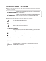
1
No. CP-SP-1316E
SPS300 A/B
Pressure Sensor/Switch
User's Manual
(Wall-Mount Type)
(Panel-Mount Type)
Thank you for purchasing the SPS300
A/B Pressure Sensor/Switch.
This manual contains information for
ensuring the correct use of SPS300
A/B pressure sensors/switches. It
also provides necessary information
for installation, maintenance, and
troubleshooting.
This manual should be read by those
who design and maintain equipment
that uses the SPS300 A/B pressure
sensors/switches. Be sure to keep this
manual nearby for handy reference.
NOTICE
Be sure that the user receives this manual before the product is used.
Copying or duplicating this user’s manual in part or in whole is
forbidden. The information and specifications in this manual are subject
to change without notice.
Considerable effort has been made to ensure that this manual is
free from inaccuracies and omissions. If you should find an error or
omission, please contact Yamatake Corporation.
In no event is Yamatake Corporation liable to anyone for any indirect,
special or consequential damages as a result of using this product.
©2010 Yamatake Corporation ALL RIGHTS RESERVED
Conventions Used in This Manual
■■ To prevent injury to the operator and others, and to prevent property damage, the following types of safety
precautions are indicated:
WARNING
CAUTION
Warnings are indicated when mishandling this product might result in
death or serious injury.
Cautions are indicated when mishandling this product might result in
minor injury to the user, or only physical damage to the product.
■■ In describing the product, this manual uses the icons and conventions listed below.
Use caution when handling the product.
The indicated action is prohibited.
Be sure to follow the indicated instructions.
Handling Precautions
Handling Precautions indicate items that the user should pay attention to when
handling the SPS300 A/B.
Note
Notes indicate information that might benefit the user.
This indicates the item or page that the user is requested to refer to.
(1), (2), (3)
Numbers within parentheses indicate steps in a sequence or parts of an
explanation.
Indicates keys on the keyboard.
[r] key
[PARAMETER]
key
[v]+
Indicates the operation of pressing the [v] key on the keyboard while the
[PARAMETER] [PARAMETER] key is pressed.
key
>>
Indicates the result of an operation, details displayed on the personal computer or
other devices, or the state of the device after operation.
i
Safety Requirements
To reduce the risk of an electric shock that could cause personal injury, follow all safety
notices in this documentation.
This symbol warns the user of a potential shock hazard where hazardous live voltages
may be accessible.
• If this equipment is used in a manner not specified by the manufacturer, the built-in protection provided by the
equipment will be impaired.
• Do not replace any component or part not explicitly specified as replaceable by your supplier.
• All wiring must be in accordance with local regulations and carried out by authorized and experienced
personnel.
• The ground terminal must be connected before any other wiring (and disconnected last).
• A switch to turn off the main power supply is required near this equipment.
• Mains power supply wiring requires (Type F) 100 mA, 250 V fuse(s) (supply voltage: 100/120 Vac).
• Mains power supply wiring requires (Type F) 50 mA, 250 V fuse(s) (supply voltage: 200/240 Vac).
● EQUIPMENT RATINGS
Supply voltage:
Frequency:
Power consumption:
100/200 Vac (SPS 300XXXXX1XX)
120/240 Vac (SPS 300XXXXX2XX)
50/60 Hz
7 W maximum
● EQUIPMENT CONDITIONS
Do not operate the instrument in the presence of flammable liquids or vapors. Operation of any
electrical instrument in such an environment constitutes a safety hazard.
Temperature:
-20 to +60 °C
Humidity:
0 to 90 % RH/40 °C
Vibration:
Frequency 10 to 60 Hz
Acceleration 4.9 m/s2 maximum
Over-voltage category: Category II (IEC 60364-4-443, IEC 60664-1)
Pollution degree:
2
● EQUIPMENT INSTALLATION
• Mount in a panel to limit operator access to the rear terminals.
• Specification for 4 to 20 mA output common mode voltage: 33 Vrms max., 46.7 V peak and 70
Vdc.
● STANDARDS COMPLIANCE
EN 61010-1, EN 61326
ii
Safety Precautions
WARNING
l
l
Before wiring, or removing/mounting the SPS300 A/B, be sure to turn the power OFF. Failure to do
so might cause electric shock.
For safety, make a good connection to ground before connecting the SPS300 A/B to the
measurement target or external control circuits. Failure to do so might cause electric shock or fire.
CAUTION
l
l
l
l
l
l
l
l
l
l
PV value zero point and full-span point have been adjusted before shipment from the factory. Do
not adjust these points again at installation. If these points must be adjusted, compensate by PV
bias.
Wire the SPS300 A/B according to the descriptions on pages 6 to 13 to ensure that the performance
of the SPS300 A/B is fully exhibited.
Wire the SPS300 A/B according to predetermined standards. Also wire the SPS300 A/B using
designated power leads according to recognized installation methods. Failure to do so might cause
electric shock, fire or faulty operation.
Use the SPS300 A/B within the operating ranges recommended in the specifications (temperature,
humidity, voltage, vibration, shock, atmosphere, etc.). Failure to do so might cause fire or faulty
operation.
Do not disassemble the SPS300 A/B, or touch components inside the SPS300 A/B. Doing so might
cause electric shock or faulty operation.
Do not touch internal components during use or immediately after turning the power OFF. Doing so
might cause burns.
If the SPS300 A/B must be wired via a conduit, provide an appropriate conduit. Also, when the
SPS300 A/B must be protected from the rain, provide a waterproof conduit, and properly seal
unused conduit holes with plugs (supplied). Failure to do so might cause electric shock, fire or faulty
operation.
Do not operate the keys with a mechanical pencil or other sharp-tipped object. Doing so might
cause faulty operation.
Do not climb on top of the SPS300 A/B or use the SPS300 A/B as a stand. Doing so might cause
faulty operation.
Output (e.g., relay output contact operation or 4 to 20 mA operation) may be unpredictable for a
brief moment when power is first supplied. Take preventive measures with the instrumentation
to delay reception of the output signal to avoid any effects. Failure to do so might cause faulty
operation of the equipment.
iii
Contents
Conventions Used in This Manual
Safety Requirements
Safety Precautions
Chapter 1.OVERVIEW
■
■
■
■
Purpose . . . . . . . . . . . . . . . . . . . . . . . . . . . . . . . . . . . . . . . . . . . . . . . . . . . . . 1
Features . . . . . . . . . . . . . . . . . . . . . . . . . . . . . . . . . . . . . . . . . . . . . . . . . . . . . 1
Functions at a Glance . . . . . . . . . . . . . . . . . . . . . . . . . . . . . . . . . . . . . . . . . . 3
Model Selection Guide . . . . . . . . . . . . . . . . . . . . . . . . . . . . . . . . . . . . . . . . . 4
Chapter 2. PART NAMES COMPONENTS AND OPERATION . . . . . . . . . . . . . . . 5
Chapter 3.INSTALLATION
■ Installation Location . . . . . . . . . . . . . . . . . . . . . . . . . . . . . . . . . . . . . . . . . . . 6
■ Pressure Inlet Connection . . . . . . . . . . . . . . . . . . . . . . . . . . . . . . . . . . . . . . 7
■ Installation . . . . . . . . . . . . . . . . . . . . . . . . . . . . . . . . . . . . . . . . . . . . . . . . . . . 8
Chapter 4.WIRING
■
■
■
■
■
■
■
SPS300
A . . . . . . . . . . . . . . . . . . . . . . . . . . . . . . . . . . . . . . . . . . . . . 9
SPS300
B . . . . . . . . . . . . . . . . . . . . . . . . . . . . . . . . . . . . . . . . . . . . . 9
Wiring Precautions . . . . . . . . . . . . . . . . . . . . . . . . . . . . . . . . . . . . . . . . . . . . 9
Cable Installation . . . . . . . . . . . . . . . . . . . . . . . . . . . . . . . . . . . . . . . . . . . . . 11
Terminal Connection Diagram (wall-mount model) . . . . . . . . . . . . . . . . . 11
Terminal Connection Diagram (panel-mount model) . . . . . . . . . . . . . . . . 12
Precautions During Use . . . . . . . . . . . . . . . . . . . . . . . . . . . . . . . . . . . . . . . 13
Chapter 5.OPERATION
5-1 Operation Summary. . . . . . . . . . . . . . . . . . . . . . . . . . . . . . . . . . . . . . . . . . . . . . 14
5-2 Operation . . . . . . . . . . . . . . . . . . . . . . . . . . . . . . . . . . . . . . . . . . . . . . . . . . . . . . 15
■ [DISPLAY] Key Operation . . . . . . . . . . . . . . . . . . . . . . . . . . . . . . . . . . . . . . 15
■ [PARAMETER] Key Operation . . . . . . . . . . . . . . . . . . . . . . . . . . . . . . . . . . 16
■ Operation by Simultaneously Pressing the [v] + [PARAMETER] Keys . . 16
■ Operation by Simultaneously Pressing the [w] + [PARAMETER] Keys . . 16
5-3 Procedures in DISPLAY/PARAMETER Modes. . . . . . . . . . . . . . . . . . . . . . . . . 17
■ DISPLAY Mode . . . . . . . . . . . . . . . . . . . . . . . . . . . . . . . . . . . . . . . . . . . . . . . 17
■ PARAMETER Mode . . . . . . . . . . . . . . . . . . . . . . . . . . . . . . . . . . . . . . . . . . . 18
■ 4 to 20 mA Mode . . . . . . . . . . . . . . . . . . . . . . . . . . . . . . . . . . . . . . . . . . . . . 21
■ PV Adjustment Mode . . . . . . . . . . . . . . . . . . . . . . . . . . . . . . . . . . . . . . . . . . 22
iv
Chapter 6.TROUBLESHOOTING
■ Alarm Code. . . . . . . . . . . . . . . . . . . . . . . . . . . . . . . . . . . . . . . . . . . . . . . . . . 25
■ Troubleshooting Procedure . . . . . . . . . . . . . . . . . . . . . . . . . . . . . . . . . . . . 25
Chapter 7.MAINTENANCE
■ Cleaning . . . . . . . . . . . . . . . . . . . . . . . . . . . . . . . . . . . . . . . . . . . . . . . . . . . . 27
■ Dielectric Strength Test . . . . . . . . . . . . . . . . . . . . . . . . . . . . . . . . . . . . . . . . 27
■ Parts Replacement . . . . . . . . . . . . . . . . . . . . . . . . . . . . . . . . . . . . . . . . . . . 27
Chapter 8. DISPOSAL . . . . . . . . . . . . . . . . . . . . . . . . . . . . . . . . . . . . . . . . . . . . . . . . . . . . 28
Chapter 9.SPECIFICATIONS
■ Specifications . . . . . . . . . . . . . . . . . . . . . . . . . . . . . . . . . . . . . . . . . . . . . . . 29
■ Accessories and Optional Parts. . . . . . . . . . . . . . . . . . . . . . . . . . . . . . . . . 31
■ External Dimension Drawing . . . . . . . . . . . . . . . . . . . . . . . . . . . . . . . . . . . 32
v
Chapter 1. OVERVIEW
■ Purpose
■ Features
The SPS300A/B Pressure Sensor/Switch is a digital indicating pressure sensor
that utilizes solid-state silicon semiconductor pressure elements. It is used to
control air, vapor, inert gas and non-corrosive liquid pressures, and to indicate
alarms. It is produced in both wall-mount and panel-mount models.
(1)High accuracy
The accuracy for the display and output range, 4 to 20 mA, is ±0.25 % FS at 0
to 50 °C. It exhibits no temperature characteristics.
(2)Pressure readings
Pressure values (PV values) are indicated by a 4-digit, 7-segment LED.
The position of the decimal point can be moved rightwards to the minimum
resolution range.
(3)4 to 20 mA output
PV values are converted to 4 to 20 mA output for either full range or a preset
span.
(4)Relay contact output
Relay ON/OFF control is carried out by contacts according to the digital
settings described below.
(5)Digital settings (set point, differential)
Relay contact and pressure differential set points can be input by key input
while monitoring process pressures (digital readings and set points can be
checked as needed).
(6)Keylock
The DISPLAY and PARAMETER mode details can be displayed and checked
in the keylock state. However, these mode settings cannot be changed. This
prevents inadvertent and erroneous setting.
(7)Display digit
The display digit setting can be changed so that the last digit is hidden. This
prevents flickering of the display caused by small pressure fluctuations.
(8)Peak hold
The previous maximum pressure value can be stored in memory and checked
when required. This value is cleared when the power supply is turned off.
(9)Filter time constant change
Sudden fluctuations in PV value can be suppressed using a preset time
constant.
1
Chapter 1. OVERVIEW
(10)HI/LO operation switching
The excitation direction of the relay can be changed as follows.
HI Relay de-energized on pressure rise, energized on pressure drop.
LO Relay energized on pressure rise, de-energized on pressure drop.
The operation LED lights when the relay is energized.
(11) PV bias
Process variables can be increased or decreased with preset values. This
allows zero point adjustment to atmospheric pressure.
(12)PV zero point and span adjustment
Zero and span point of PV values are adjustable.
(13)Current value manual output (SPS300A)
Manually set pressure values can be output in order to check controllers and
recorders during trial runs. (Relay control also is carried out.)
(14)Self-diagnostics
Abnormal conditions are monitored by an integrated microcomputer so that
remedial measures can be quickly carried out.
2
Chapter 1. OVERVIEW
■ Functions at a Glance
DISPLAY key
(display mode)
PV value (pressure value)
Displayed digits setting
Self-diagnostics
Set point
SP 1
SP 2
Digital display
Keylock
PARAMETER key
(parameter mode)
Differential
DIF 1
DIF 2
PV bias
Peak hold
Digital setting
Filter time constant change
KEYLOCK
RELAY1 RELAY2
PV
SP1
SP2
ENT
DISPLAY PARAMETER
HI/LO selection
+ PARAMETER key
(SPS300A only)
Initialize current
+ PARAMETER key
SPS300A
4 to 20 mA
&
RELAY 1
ON/OFF
Relay contact output
Current value scaling
4 mA setting
20 mA setting
Current output
Manual current output
SPS300B
RELAY 1
ON/OFF
&
RELAY 2
ON/OFF
PV adjustment
PV zero adjustment
PV full span adjustment
Initialize PV
3
Chapter 1. OVERVIEW
■ Model Selection Guide
Example
I
II
III
IV
V
SPS300A
100
A
1
10
I
II
III
IV
V
Basic model
No.
Range
Mounting
Power
voltage
Additional
processing
Contents
SPS300A
Intelligent pressure sensor
4 to 20 mAdc output + relay 1 contact output
SPS300B
Intelligent pressure switch
2 relay contact outputs
See table
below
A
Wall-mount model
B
Panel-mount model
1
100/200 Vac, 50/ 60 Hz
2
120/240 Vac, 50/ 60 Hz
10
None
1D
With data sheet
1T
With tropicalization treatment
1B
With data sheet and tropicalization treatment
1Y
With traceability certification
Range Code and Unit
Range
kgf/cm2
code
100 0 to
1
101
4
0
to
2
Range
code
200 201
kPa
0 to
Range
code
100
300 0 to
200
301
psi
0 to
Range
code
15
700 0 to
0 to
30
0 to 1520
701
mmHg
Range
bar
code
760
800 0 to
801
0
to
MPa
1
Range
code
–
2
–
–
–
102
0
to
5
202
0 to
500
302
0 to
75
702
0 to 3800
802
0
to
5
–
103
0
to 10
203
0 to 1000
303
0 to 150
703
0 to 7600
803
0
to
10
903
0
to 1
104
105
0
0
to 20
to 35
204
205
0 to 2000
0 to 3500
304
305
0 to 300
0 to 500
–
–
804
805
0
0
to
to
20
35
904
905
0
0
to 2
to 3.5
–
–
106
-1
to +1
206
-100 to +100
306
-15 to +15
706
-760 to +760
806
-1
to +1
–
107
-1
to +10
207
-100 to +1000
307
-15 to +150
707
-760 to+7600
807
-1
to +10
907
108
0.2 to
1
208
20 to
100
308
3 to
15
708
152 to
109
0
3
209
300
309
0 to
45
709
to
0 to
–
–
-0.1 to +1
760
808
0.2 to
1
–
–
0 to 2280
809
0
3
–
–
to
110
-1
to +20
210
-100 to +2000
310
-15 to +300
–
–
810
-1
to +20
910
-0.1 to +2
111
-1
to +35
211
-100 to +3500
311
-15 to +500
–
–
811
-1
to +35
911
-0.1 to +3.5
Chapter 2. PART NAMES COMPONENTS
AND OPERATION
RELAY 1 indicator
KEYLOCK indicator
RELAY 2 indicator
Present value indicator
Minus indicator
KEYLOCK
Pressure value indicator
(PV value indicator)
RELAY1 RELAY2
PV
SP1
SP2
Up key
Left key
Down key
ENT
DISPLAY
PARAMETER
DISPLAY key
l Entering numerical values with the DISPLAY key
• Move the focus to the left or right with the [
increment or decrement the value with the [
• Key in the value, and press the [ENT] key.
RELAY 1 setting indicator
RELAY 2 setting indicator
Right key
ENT key
PARAMETER key
], [ ], [ ], [
] or [ ] keys.
l Entering numerical values with the PARAMETER key
• Press the [ENT] key.
• Move the focus to the left or right with the [ ] or [
decrement the value with the [ ] or [ ] keys.
• Press the [ENT] key.
] keys, and
] keys, and increment or
5
Chapter 3. INSTALLATION
■ Installation Location
Avoid installing the SPS300 A/B in locations such as the following:
• Locations with temperature outside of the operating temperature range of -20 to
60 °C
• Locations with humidity exceeding the operating humidity range of 90 % RH
• Locations subject to sudden changes in temperature and condensation
• Locations subject to corrosive or flammable gases
• Locations subject to large amounts of dirt, dust, salt, conductive substances
such as iron powder, or organic solvents
• Locations that directly subject the device to vibration or impact
• Locations subject to direct sunlight
• Locations subject to large amounts of water or rain
• Locations subject to splashing by oil or chemicals
• Locations where strong magnetic or electrical fields are generated
• Locations where connector joints are subject to surge pressure
Handling Precautions
• Be sure to use the wall mounting bracket for the wall mounting
model.
• Be sure to use the panel mounting bracket for the panel mounting
model.
6
Chapter 3. INSTALLATION
■ Pressure Inlet Connection
Handling Precautions
• Do not directly hold the unit when connecting the pipe to the pressure
inlet. Doing so might damage the unit.
l Correct connection
• Wall mount
• Panel mount
l Incorrect connection
• Dropping
• Striking
• Screwing-in, pushing, or pulling
• Upside-down or horizontal position
8888
8888
7
Chapter 3. INSTALLATION
n Installation
l Panel cutout size
Unit: mm
+0.4
91.3 –0
(4
−R
2±
0.5
)*
150 min.
(115.3 +0.8
)*
–0
115.3
+0.4
–0
(91.3 +0.8
)*
–0
118 min.
* Apply the cutout hole dimensions in
parentheses to round corners.
l Installation
• Wall mounting bracket installation
• Wall mounting bracket diagram
3 screws (user-supplied)
Wall mounting bracket
Part No. 81446092-001
(1 set)
KEYLOCK
RELAY1 RELAY2
PV
SP1
SP2
ENT
DISPLAY
PARAMETER
Four M4 screws (included)
• Panel mounting bracket installation
Example of siphon installation
Air vent
Siphon
Part No. J-14026
Panel mounting bracket
Part No. 81446093-001
(1 set)
8
Chapter 4. WIRING
■ SPS300
A
The terminal board can be accessed by opening the front cover.
Protective grounding terminal
Terminal label
Terminal board
Loosen 4 screws
on front panel.
If the front cover does not open,
insert a screwdriver under the hinge
and pry the cover up as shown
in the figure below.
■ SPS300
B
Protective grounding terminal
■ Wiring Precautions
• To prevent electric shock on panel-mounted models, prevent direct contact with
the terminals by the operator.
• A switch in the main power supply is required within the operator's reach.
* Provide a fuse appropriate for the mains power supply in the instrument
power supply wiring.
Type F 100 mA, 250 Vac fuse (supply voltage: 100/120 Vac)
Type F 50 mA, 250 Vac fuse (supply voltage: 200/240 Vac)
9
Chapter 4. WIRING
• Ground one point on the protective ground terminal.
Shielded wire
Grounding terminal board
Ground
• Shielded cables should be grounded by connection to an earth bar.
•
Ground according to the following conditions:
Grounding type: Grounding resistance of 100 Ω max.
Grounding wire: Mild copper wire of more than 2 mm2
Grounding wire length: 20 m max.
• If waterproofing is required, seal the conduit hole with a waterproof conduit.
• Devices and systems to be connected to this unit must have the basic insulation
sufficient to withstand the maximum operating voltage levels of the power
supply and input/output parts.
• Separate as far as possible low-voltage output signal cables from power cables
with a voltage higher than 100 V. Do not put them in the same conduit or duct.
• Use crimped terminals that are compatible with M3.5 screws.
When installing the SPS300 A/B at locations subject to much vibration or
shock, be sure to use round terminal lugs that cannot come loose from the
terminals.
Unit: mm
7.5
7.3 max.
4.3 mm dia.
6.6 max.
9.0
18.6
• Be careful not to scratch electronic parts, lead wires, and other components with
a screwdriver or other tools.
• First confirm the model number of your unit, and then connect cables according
to the proper connection diagram.
• After wiring, check that the wiring is correct.
10
Chapter 4. WIRING
■ Cable Installation
Wire cables as shown in the figure below.
Waterproof conduit
Ex: Seiwa Electric SC lock SK type
KEYLOCK
RELAY1 RELAY2
PV
4 to 20 mA
low-voltage cable
SP1
SP2
Power line,
power cable
ENT
DISPLAY PARAMETER
Lower below conduit hole
(this prevents water drops
from entering the SPS300 A/B
by running along the cable.)
■ Terminal Connection Diagram (wall-mount model)
l SPS300A
Current output
Relay 1 output
4 to 20 mA
Load resistance:
300 Ω max.
1
2
+
3
Power supply
250 Vac, 3 A max.
200 Vac or 240 Vac
Load Load
4
–
5
100 Vac or 120 Vac
6
7
8
9
NO
NC
COM
Protective ground supply system conductor
l SPS300B
Relay 2 output
Relay 1 output
250 Vac, 3 A max.
250 Vac, 3 A max.
Load Load
Load Load
1
2
NC
3
NO
COM
4
5
NC
Power supply
200 Vac or 240 Vac
100 Vac or 120 Vac
6
7
8
9
NO
COM
Protective ground supply system conductor
11
Chapter 4. WIRING
■ Terminal Connection Diagram (panel-mount model)
l SPS300A
Current output
Relay 1 output
4 to 20 mA
Load resistance:
300 Ω max.
1
+
2
–
250 Vac, 3 A max.
Load Load
3
4
5
6
NO
NC
COM
7
8
9
100 Vac or 120 Vac
Protective ground supply
system conductor
200 Vac or 240 Vac
Power supply
l SPS300B
Relay 2 output
Relay 1 output
250 Vac, 3 A max.
250 Vac, 3 A max.
Load Load
Load Load
1
2
NC
3
4
NO
5
NC
COM
7
6
NO
COM
8
9
100 Vac or 120 Vac
Protective ground supply
system conductor
200 Vac or 240 Vac
Power supply
12
Chapter 4. WIRING
■ Precautions During Use
• Calibrate pressure at least once per year.
• This unit is a precision instrument. Protect the unit from excessive shock during
installation or operation.
• This unit is not free-standing. Firmly fix onto a mounting plate.
• Do not hold the case while threading the pipe into unit. Hold the hexagonal nut
to secure the SPS300 A/B while attaching the pipe.
• Install the SPS300 A/B upright only. Installing the SPS300 A/B horizontally,
for example, may result in errors.
• The SPS300 A/B is designed to be rain-proof (JIS C 0920 Class 3), but it
should be installed away from direct sunlight or rain. Also, when the SPS300
A/B must be protected from the rain, use a waterproof conduit.
• Do not exceed allowable pressure limits. If abnormal pressures are applied
to the SPS300 A/B, drift in readout accuracy may occur. Check the unit for
abnormalities after use.
• The SPS300 A/B is designed to have a sufficient tolerance when allowable
pressures are exceeded. However, use caution when opening and closing valves,
when pressure surge through non-compressible liquids might damage the
pressure sensor.
• Protect liquid-contacting parts from freezing. If freezing is anticipated, protect
with insulation or heating.
• Reduce the pressure inlet temperature to 60 °C or lower by installing a siphon
when measuring high-temperature media.
• Wait for at least 10 minutes after turning the power ON for the unit to stabilize.
• Output (e.g., relay output contact operation or 4 to 20 mA operation) may be
unpredictable for a brief moment when power is first supplied. Take preventive
measures with the instrumentation to delay reception of the output signal
to avoid any effects. Failure to do so might cause faulty operation of the
equipment.
• For details, contact Yamatake Corporation or your dealer.
13
Chapter 5. OPERATION
5 - 1
Key operation
DISPLAY key
PARAMETER
key
v+
PARAMETER
key
w+
PARAMETER
key
Operation Summary
Mode
Function
PV value display
SP1 value setting
DISPLAY mode SP2 value setting
PARAMETER
mode
4 to 20 mode
PV adjustment
mode
SPS300A SPS300B
Display
Factory setting
characters and
lamp states
PV lamp lit
–
SP1 lamp lit
*
SP2 lamp lit
*
m
m
X
m
m
m
Keylock
m
m
l0.ck
(LOCK)
Canceled
DIFF1 value setting
m
m
di.f 1
(DI F1)
*
DIFF2 value setting
X
m
di.f2
(DI F2)
*
Digital filter time
constant setting
m
m
fi.lt
(FILT)
1.00 s
PV bias value setting
m
m
bi.as
(BIAS)
0
Peak hold value display
m
m
peak
(PEAK)
–
Relay 1 action state
setting
m
m
HI
Relay 2 action state
setting
el 1
(REL 1)
X
m
HI
4 to 20 mA manual
output (relay control
function provided)
el2
(REL 2)
m
X
mMal
(MANUAL)
–
4 mA output point range
scaling value setting
m
X
4 ad
(4 AD)
Range model
low limit
20 mA output point
range scaling value
setting
m
X
20ad
(20 AD)
Range model
high limit
4 to 20 mA output
values initialization
m
X
cui.M
(CURRENT
INITIALIZE)
–
PV zero adjusting value
setting
m
m
pv 0
(PV 0)
–
PV span adjusting value
setting
m
m
pvfs
(PV FULL
SCALE)
–
PV all adjusting value
initialization
m
m
pvi.M
(PV
INITIALIZE)
–
Note: Press v + PARAMETER, w + PARAMETER key first, and then the PARAMETER key.
* The least significant digit is set to "1" regardless of the range code.
Ex.: 0.1 kPa in case of 0.0 to 200.0 kPa range model.
14
Chapter 5. OPERATION
5 - 2
Operation
n [DISPLAY] Key Operation
Each press of the [DISPLAY] key sequentially accesses the following functions:
Step
1
Key operation
Press [DISPLAY] key
Display
Description
PV value display
PV LED lights.
To shift highlighted digit, press [v] or
[w] key.
Set highlighted digit with [ENT] key.
PV value
PV
SP1 value display
SP1 LED lights.
RELAY 1 LED lights when relay 1 is
energized.
Setting range: within the Display/
Setting range of Table 1 (page 31)
RELAY1
Press [DISPLAY] key
Keylock disable
2
SP1 value
SP1
RELAY2
3
Press [DISPLAY] key
SP2 value
SP2
4
Press [DISPLAY] key
Note: SPS300B only.
SP2 value display
SP2 LED lights.
RELAY 2 LED lights when relay 2 is
energized.
Setting range: within the Display/
Setting range of Table 1 (page 31)
L0.Ck display
Keylock can be set.
L0.CK.
• The RELAY LED lights when the relay is energized.
• The lighting direction of the RELAY LED will change according to the HI/LO
setting.
Enabling and canceling the keylock
Keylock enable
Step
Key operation
Display
Description
5
Press [ENT] key
f
6
Press either [r] or [s]
key
l
(F=Free)
Keylock cancel
Press [ENT] key
8
Press either [r] or [s]
key
l
display blinks.
(L=LOCK)
KEYLOCK
7
f display blinks.
l
l display
KEYLOCK LED lights.
Keylock is ON
KEYLOCK
f
KEYLOCK
9
Press [ENT] key
f
f display blinks.
KEYLOCK LED lights.
f display
KEYLOCK LED goes out.
Keylock canceled.
15
Chapter 5. OPERATION
n [PARAMETER] Key Operation
Step
1
Key operation
Press [PARAMETER]
key
Display
Description
DI.F 1
Differential 1 value setting
Setting range: within the Display/
Setting range of Table 1, but only for
positive values, excluding zero
2
Press [PARAMETER]
key
DI.F2
(SUS300B only)
Differential 2 value setting
Setting range: within the Display/
Setting range of Table 1, but only for
positive values, excluding zero
3
Press [PARAMETER]
key
FI.LT
Digital filter time constant
Setting range: 0.00 to 99.99 s
4
Press [PARAMETER]
key
BI.As
PV bias value setting
Setting range: within the Display/
Setting range of Table 1 (page 31)
5
Press [PARAMETER]
key
peak
Peak hold value display
6
Press [PARAMETER]
key
rel 1
Relay 1 action state setting
7
Press [PARAMETER]
key
rel2
(SPS300B only)
Relay 2 action state setting
n Operation by Simultaneously Pressing the [v] + [PARAMETER] Keys
This is displayed only on the SPS300A.
Step
Key operation
Display
1
Press [v] +
[PARAMETER] key
M.Mal
2
Press [PARAMETER]
key
4�ad
3
Press [PARAMETER]
key
20ad
4
Press [PARAMETER]
key
cu1.M
Description
4 to 20 mA manual output (relay
control function provided.)
Setting range: within the Display/
Setting range of Table 1 (page 31)
4 mA output point range scaling value
setting
Setting range: within the Display/
Setting range of Table 1, but less than
20 mA output point range scaling
value
20 mA output point range scaling
value setting
Setting range: within the Display/
Setting range of Table 1, but more
than 4 mA output point range scaling
value
4 to 20 mA output value initialization.
Factory settings are restored.
n Operation by Simultaneously Pressing the [w] + [PARAMETER] Keys
Note
• Refer to "PV zero point adjustment function", "PV value full-span point
adjustment function" and "PV value zero point and full-span point
adjustment initialization" before carrying out this operation (pages 22, 23 and
24).
Step
16
Key operation
1
Press [w] +
[PARAMETER] key
2
3
Display
Description
pv�0
PV zero adjustment setting
Press [PARAMETER]
key
pvf5.
PV span adjustment setting
Press [PARAMETER]
key
pvi.M
PV all adjustment initialization
Factory settings are restored.
Chapter 5. OPERATION
5 - 3
Procedures in DISPLAY/PARAMETER Modes
n Display Mode
l PV function/ decimal point position change function (PV)
・ Entering the PV function
(1) There is no display for 1 s after power-on. After one second, the PV lamp
lights, and the measured pressure (PV) is displayed.
(2) By pressing the [DISPLAY] key the mode can be changed from other
modes to the PV function.
(3) Pressing the [DISPLAY] key in the keylock function returns to the PV
function.
・ Exiting the PV function
(1) Pressing the [DISPLAY] key changes the function from PV to SP1.
(2) Pressing the [PARAMETER] key enters the PARAMETER mode.
The display changes to di.f i.
・ PV function description
(1) The PV value is displayed, and the PV LED lights.
(2) To change the position of the decimal point (with keylock disabled)
・Set PV to the desired number of digits with the [
] or [
] keys.
・Further shifting with the [ ] key is not possible when the decimal point
is at the rightmost position (4th digit).
・Likewise, shifting with the [ ] key is possible only up to the position
where the full-span value is the most significant digit.
・Values lower than the display digit are rounded to the nearest whole
number.
(3) The display digit is set and fixed with the [ENT] key.
The display digit will return to its default, if the [ENT] key is not pressed
before the power is turned OFF.
17
Chapter 5. OPERATION
l SP1 or SP2 function (SP1), (SP2)
The procedure for entering and exiting this function is the same as that described
on the previous page.
• Description
Setting method
• Select the digit to be set by pressing the [
blinking digit can be changed.
] or [
] key. The value of the
• Set the desired value by pressing the [ ] or [ ] keys. Each press of the
[ ] or [ ] keys increments or decrements the value. Pressing the [ ] key
when “9” is indicated changes the value to “0,” and the next higher digit is
incremented by 1. Pressing the [ ] key when “0” is indicated changes the
value to “9,” and the next higher digit is decremented by 1.
• When you press the [ENT] key after setting to the desired numerical value,
the digit blinks once, and then stops blinking to indicate that the value has
been set. Control output is also executed at the same time.
• To reset the value, press the [
], [
], [
] or [
] keys.
Handling Precautions
• Since the value displayed on the PV display has been rounded to the
nearest whole number, the relay may not operate even if the same
value is displayed for the set point and the PV.
• This is more likely to happen when the PV decimal point position has
been moved.
• The relay operates when the internally calculated PV value matches
the set point.
n PARAMETER Mode
l Differential (di.f 1), (di.f2)
The procedure for entering and exiting functions is the same as that described on
the previous page.
• Description
Setting method
Pressing the [ENT] key displays set point. Repeat the procedures described in
“SP1 or SP2 function.”
18
Chapter 5. OPERATION
l Filter time constant display/setting function (fI.lt)
(1) Explanation
Pressing the [ENT] key displays the set value.
PV filter setting
PV (process variable)
SP
(set point)
Time
PV filter effect
PV (process variable)
SP
(set point)
Time
• This item is for setting the PV filter time constant.
• The PV filter suppresses sudden changes in the PV (input). Setting this item
to “0.0” disables the filter. The higher this value is set, the more effective the
PV filter becomes.
(2) Setting method
Set as described in “SP1 or SP2 function” on the previous page.
l PV bias function (bI.as)
(1) Explanation
Pressing the [ENT] key displays the set value.
The PV value is displayed, or output as a 4 to 20 mA signal, after being biased
by the set value.
Handling Precautions
In the PV adjustment mode
• Since the PV bias function is independent, it remains unchanged if
either PV zero point or PV full-span point values are adjusted.
(2) Setting method
Set as described in “SP1 or SP2 function” on the previous page.
19
Chapter 5. OPERATION
l Peak hold display/setting function (peak)
(1) Setting method
Pressing the [ENT] key displays the last maximum pressure value. (This value
is cleared when the power is turned OFF.)
(2) Clear procedure
Pressing the [ENT] key causes the 6.0. (GO) display to blink.
Pressing the [ENT] key again clears the display, and updates the peak hold
value.
(3) Display cautions
Zero will be displayed for 20 seconds after the power is turned ON.
Handling Precautions
• Values exceeding the rated pressure should only be used as a
reference, since readout accuracy decreases by about ±5 %.
• Also, drift in readout accuracy may occur if a pressure exceeding the
rated pressure is applied.
l Relay 1 or 2 action state selection ( el 1), ( el2)
(1) el 1 is displayed in the relay 1 function mode, while el2 is displayed in
the relay 2 function mode.
(2) Pressing the [ENT] key de-energizes the relay as follows:
If input is greater than the set point during h i. pressure increase, the relay is
de-energized (pressure rise control).
If input is less than set the point during l 0. pressure decrease, the relay is
de-energized (pressure drop control).
(3) Pressing the [ ] or [ ] keys reverses the setting state.
Pressing the [ENT] key loads and displays set points.
H�1.
Differential
L�0.
Relay energized
Relay energized
De-energized
De-energized
Pressure increase
SP1 or SP2
Pressure increase
(Setting 1) (Setting 2)
(4) The operation LED is lit when the relay is energized.
20
Differential
SP1 or SP2
(Setting 1) (Setting 2)
Chapter 5. OPERATION
n 4 to 20 mA Mode
l Current value manual output function (mMal)
• Setting method
(1) Pressing the [ENT] key displays and outputs the current PV.
(2) If a desired PV is set using the[ ], [ ], [ ] or [ ] keys, the new PV is
displayed and output.
l 4 mA output point range scaling (4 ad)
• Description
- 4 ad is displayed in the 4 Ad function mode.
- Pressing the [ENT] key displays the value at the 4 mA output point.
• Setting method
(1) Input the desired value for the 4 mA output point using the [ ], [ ], [ ],
[ ] keys.
(2) Pressing the [ENT] key displays the new value.
(3) The 4 to 20 mA output value is also changed as a result of the above change.
l 20 mA output point range scaling (20ad)
• Description
- 20ad is displayed in the 20Ad function mode.
- Pressing the [ENT] key displays the value at the 20 mA output point.
• Setting method
(1) Input a desired value for the 20 mA output point by the [ ], [ ], [ ], [ ]
keys.
(2) Pressing the [ENT] key displays the new value.
(3) The 4 to 20 mA output value is also changed as a result of the above change.
l 4 to 20 mA output value initialization (cui.M)
• Description
cui.M is displayed in the initialize function mode.
• Setting method
(1) Pressing the [ENT] key causes 6.0. to blink.
(2) Pressing the [ENT] key again in this state resets the 4 to 20 mA output to the
factory setting.
(3) This function is effective when resetting the 4 to 20 mA output value to the
default if 4 mA output point range scaling or 20 mA output point range
scaling adjustment has failed.
21
Chapter 5. OPERATION
n PV Adjustment Mode
l PV zero point adjustment function (pv 0)
Handling Precautions
• PV zero point and full-span point were adjusted before shipment from
the factory. Do not adjust these points again at installation. If adjustment
is necessary, use the PV bias.
• When adjusting the zero point or full-span point during maintenance or
calibration, follow the instructions below.
• If PV zero point adjustment or PV value full-span point adjustment is not
successful, initialize the settings following the description in “PV value
zero point and full-span point adjustment initialization” below.
• Setting method
Set the supply pressure to either zero or a fixed value.
(1) Pressing the [ENT] key displays the current PV value (based on the factory
settings and excluding the bias value).
(2) Enter the numerical value indicated on the reference manometer by the [ ],
[ ], [ ], [ ] keys.
(3) Pressing the [ENT] key calculates and displays the current PV value so that
it matches the value input.
(4) The difference between PV and input values is calculated in order to change
the bias and ratio of the subsequent PV value.
(5) The following figure illustrates the relationship caused by this adjustment:
B-A
Y=
(X - a) + A
b-a
a (B - A)
B-A
=
X+A
b-a
b-a
After
adjustment
B
Bias adjustment
where,
Y = Value after adjustment
X = Value before adjustment
A, B: Values after adjustment
a, b: Values before adjustment
A
b
Before
adjustment
a
Zero
Full span point
Adjustment
• To reset, repeat the above procedure.
• The 4 to 20 mA output is also changed as a result of the above adjustment.
Handling Precautions
• Since the PV bias value is not adjusted by the procedure described
here, reset it to zero before carrying out the above adjustment.
• The bias adjustment value after PV zero adjustment is independent of
the PV bias value (page 19).
• Reset the filter time constant to zero and adjust it after the PV value
has stabilized.
22
Chapter 5. OPERATION
l PV full-span adjustment function (pvf5.)
Handling Precautions
• PV zero point and full-span point were adjusted before shipment from
the factory. Do not adjust these points again at installation. If adjustment
is necessary, use the PV bias.
• When adjusting the zero point or full-span point during maintenance or
calibration, follow the instructions below.
• If PV zero point adjustment and PV value full-span point adjustment
is not successful, initialize the settings following the description in “PV
value zero point and full-span point adjustment initialization” below.
• Setting method
Supply full-span pressure until it stabilizes.
(1) Pressing the [ENT] key displays the current PV value (based on the factory
settings but excluding the bias value).
(2) Enter the numerical value indicated on the reference manometer by the [ ],
[ ], [ ], [ ] keys.
(3) Pressing the [ENT] key calculates and displays the current PV value so that
it matches the value input.
Handling Precautions
• Since the PV bias value is not adjusted by the procedure described
here, reset it to zero before carrying out the above adjustment.
• Reset the filter time constant to zero and adjust it after the PV value
has stabilized.
• After adjusting the PV value zero point, be sure to press the
[DISPLAY] key to check the PV value.
B-A
Y=
(X - a) + A
b-a
a (B - A)
B-A
=
X+A
b-a
b-a
After
adjustment
B
Bias adjustment
where,
Y = Value after adjustment
X = Value before adjustment
A, B: Values after adjustment
a, b: Values before adjustment
A
b
Before
adjustment
a
Zero
Full span point
Adjustment
23
Chapter 5. OPERATION
l PV value zero point and full-span point adjustment initialization (pvi.M)
pvi.M is displayed in the initialize function mode.
• Setting method
(1) Pressing the [ENT] key causes 6.0. to blink.
(2) Pressing the [ENT] key again in this state resets the PV value adjustment to
the factory setting.
(3) This function is effective for adjusting the PV zero point and full-span point
to the defaults if PV zero point adjustment or PV full-span point adjustment
has failed.
24
Chapter 6
TROUBLESHOOTING
n Alarm Code
Alarm code
al 1
al 2
Cause of alarm
Insufficient pressure (application
of pressure lower than the Display/
Setting range of Table 1 on page 31)
Insufficient pressure (application of
pressure higher than the Display/
Setting range of Table 1 on page 31)
al 3
Lower than -20 °C (inside case)
al 4
Higher than 80 °C (inside case)
al 5
User settings memory error
al 6
Factory setting memory error
Corrective measures
Apply rated pressure and confirm
normal operation.
Apply rated pressure and confirm
normal operation.
Check operation in recommended
temperature range.
Check operation in recommended
temperature range.
Check all settings and reset if
necessary.
Ask for repair
• PV values and alarm codes are alternately displayed.
• Outputs in this state are not guaranteed to be normal.
n Troubleshooting Procedure
l PV value not displayed
Check power voltage.
Make sure that internal connectors are not loose.
Contact a Yamatake sales agent.
l PV value error
Check zero pressure after exposing to atmospheric pressure.
Set PV bias to zero, and check PV after applying pressure.
See page 19.
Initialize all adjustable PV values, and check PV after applying pressure.
See page 24.
Contact a Yamatake sales agent.
25
Chapter 6. TROUBLESHOOTING
l 4 to 20 mA error
Check zero pressure after exposing to atmospheric pressure.
Check 4 to 20 mA output scaling.
See page 21.
Initialize all 4 to 20 mA set values.
See page 21.
Contact a Yamatake sales agent.
l Incorrect operation
Power reset
Turn power OFF and wait at least 10 minutes before
turning back ON.
Inspect 4 to 20 mA output wiring and line voltage wiring.
Ensure that line voltage is noise-free.
Ensure that output leads are noise-free.
Check ambient conditions to ensure that they do not
exceed general specifications.
Contact a Yamatake sales agent.
26
Chapter 7
n Cleaning
MAINTENANCE
To remove dirt from the SPS300 A/B, wipe with a soft, dry cloth.
n Dielectric Strength Test
Remove the dielectric strength test pin from next to the transformer (inside the
case) before starting the dielectric strength test on wall-mount types. Re-insert the
pin securely at the end of test.
n Parts Replacement
Parts must be replaced by authorized personnel only.
l Replacing packing
If rain protection is required, replace the rubber packing (Part No. 81403871001) if one year has passed since the seal was broken.
How to replace the rubber packing
(1) Disconnect the connector.
(2) Replace the rubber packing.
(Mount new packing in original
position.)
(3) Reconnect the connector.
Rubber packing
NC
Relay 2
NO COM NC
Relay 1
NO COM
200V
100V
Dielectric strength
test pin
Connector
l Replacing fuses
Use specified standard parts when replacing fuses on the mains power supply
wiring.
Standard:
Type:
Rated voltage:
Rated current:
IEC127
F
250 V
100 mA (supply voltage: 100/120 Vac)
50 mA (supply voltage: 200/240 Vac)
27
Chapter 8
DISPOSAL
When discarding the SPS300A/B dispose of it appropriately as industrial waste in accordance with local laws and
regulations.
28
Chapter 9
SPECIFICATIONS
n Specifications
Applicable
fluids
Pressure
detector
Display and
setting
Output unit
Gases and liquids, except those that may corrode pressure receiver material (SUS316L, SUS316)
Applicable fluid
-20 to +60°C (without condensation)
temperature
Pressure receiver
Oil-filled diaphragm structure protected by oil seal
structure
Pressure detecting
Piezo-resistance silicon pressure detector
element
Fluid-contacting
Diaphragm: SUS316L
material
Pressure inlet: SUS316L, SUS316
Display/Setting
Digital 4 digit, 7-segment LED display
method
Display/Setting range See Table 1 below.
Display digit change
Lowest significant digit can be hidden to prevent flickering caused by small pressure
fluctuations.
Input digital filter
0.00 to 99.99 sec., variable first-order lag filter system
0.00: Filter OFF
Response speed
Display output
100 ms
Current output
50 ms
Input digital filter = 0.00 at 63 % response
Relay contact output
50 ms
±1 % FS ±1 digit (±2 % FS ±1 digit for range codes 102,
Readout -20 to 0 °C Positive pressure range
202, 302, 702 and 802)
accuracy and
50 to 60 °C Negative pressure range ±2 % FS ±1 digit
*1
Positive pressure range
±0.25 % FS ±1 digit
0 to 50°C
Negative pressure range ±1 % FS ±1 digit
*1 Overall accuracy including linearity, offset, hysteresis, and their temperature/
power voltage characteristics.
Model name
Intelligent pressure sensor
Basic model No.
SPS300A
Output type
Current + relay contact (SPDT)
Output rating
Current
Current 4 to 20 mA (external load resistance: max.
value
300 Ω)
Scaling Scaling can be set.
Manual Manual output value can be set.
Relay contact
SP1
250 Vac 3 A resistive load *2
Model name
Intelligent pressure switch
Basic model No.
SPS300B
Output type
Relay contact (SPDT) + relay contact (SPDT)
Output rating
Relay contact
SP1
250 Vac 3A resistive load *2
Relay action
Relay contact
SP2
250 Vac 3 A resistive load *2
*2 Mechanical life: 50,000,000 cycles
Electric life: 100,000 cycles (with rated load)
Hi Relay de-energized on pressure rise, energized on pressure drop.
Selectable
Lo Relay energized on pressure rise, de-energized on pressure drop.
Relay action when HI is selected
Relay action when LO is selected
Differential
Differential
Energized
Energized
De-energized
De-energized
Rise
SP
Rise
SP
Output update cycle
25 ms
±1 % FS (±2 % FS for range codes 102, 202, 302, 702
Output
-20 to 0 °C Positive pressure range
and 802)
accuracy and
*3
50 to 60 °C Negative pressure range ±2 % FS
Positive pressure range
±0.25 % FS
0 to 50°C
Negative pressure range ±1 % FS
*3 Overall accuracy including linearity, offset, hysteresis, and their temperature/
power voltage characteristics.
29
Chapter 9. SPECIFICATIONS
Functions
PV adjustment
Peak hold
Keylock
Self-diagnostics
Alarms
General
specifications
Breakdown pressure
Allowable pressure
Rated voltages
Working voltage
range
Power consumption
Insulation resistance
Dielectric strength
Lightning surge
countermeasure
Working ambient
temperature
Ambient storage
temperature
Ambient working
humidity
Vibration resistance
Shock resistance
Main unit materials
PV bias, PV zero point and span adjustment
The last maximum pressure value can be held in memory, displayed, and checked.
This value is cleared when the power is turned OFF. The peak hold function does
not operate for about 20 seconds after turning the power ON.
This function is used to prevent inadvertent change to settings. The contents of the
DISP and PARAMETER modes can be displayed.
Checksum is calculated for user setting and backups, and for manufacturer settings
(adjusted values) and backups. If an error is found, an alarm is output.
Overscale (pressure exceeding the Display/Setting range of Table 1) and abnormal
working temperature (higher than +80 °C or lower than -20 °C) are displayed by
alarm codes.
3 times the span
(1.5 times with range codes 105, 109, 111, 205, 209, 211, 305, 309, 311, 709, 805,
809, 811, 905 and 911)
1.1 times the span
(Equal to the span with range codes 105, 109, 111, 205, 209, 211, 305, 309, 311,
709, 805, 809, 811, 905 and 911)
100/200 Vac 50/60 Hz or
120/240 Vac 50/60 Hz
100/200 Vac: 82 to 110 or 164 to 220 V 50/60 Hz ±2 Hz
120/240 Vac: 99 to 132 or 198 to 264 V 50/60 Hz ±2 Hz
7 W max.
At least 50 MΩ across both primary power supply and case, and primary and
secondary power supplies using a 500 Vdc megger.
1500 Vac, for 1 minute or 1800 Vac, for 1 second across both primary power supply
and case, and across primary and secondary power supplies.
Caution:Wall-mount model is provided with a lightning surge protector for the power
supply. A current will flow if a voltage of higher than about 1000 V is applied
across the power supply and the case. To prevent this, disconnect the
dielectric strength test pin from the power supply board before carrying
out the dielectric strength test. Reinsert the pin after the test.
Wall-mount model: A lightning surge protector is built in (10 kV across power supply
and sensor , 6 kV across the power supply and the case).
Panel-mount model: No lightning surge protector provided.
-20 to +60 °C (without freezing)
-20 to +80 °C (without freezing)
40 °C, 90 % RH max. (without condensation)
4.9 m/s2 max., 10 to 60 Hz in X, Y, and Z directions, 2 hours each
490 m/s2 max. in X, Y, and Z directions, 3 times
Case/cover: diecast aluminum
Door, window, decorative panel: polycarbonate
Pressure inlet
Rc 1/4 (liquid temperature must not be higher than 60 °C)
Use a siphon or the likje to reduce temperature.
Structure standard
JIS C 0920 Class 3. Rain-proof type (wall-mount model)
Main unit color
Case: gray. Cover, window, decorative panel: dark gray. Door: smoke gray
Mass
Approx. 1.1 kg
Mounting position
Vertical
Mounting
Wall-mount or panel flush-mount
Mounting state
Permanent connected device
Altitude
2000 m max.
Over-voltage category Category II (IEC60364-4-443, IEC60664-1)
Pollution degree
2
Standards compliance EN 61010-1, EN 61326
30
Chapter 9. SPECIFICATIONS
Table 1 Ranges and units
kgf/cm2
Display/Setting
range
0 to
1 -0.100 to +1.100
0 to
2 -0.200 to +2.200
0 to
5 -0.500 to +5.500
0 to
10 -1.00 to +11.00
0 to
20 -1.20 to +22.00
0 to
35 -1.20 to +38.50
-1 to
+1 -1.200 to +1.100
-1 to +10 -1.20 to +11.00
0.2 to
1 -0.100 to +1.100
0 to
3 -0.300 to +3.300
-1 to +20 -1.20 to +22.00
-1 to +35 -1.20 to +38.50
mmHg
Range
Display/Setting
range
0 to 760 -76.0 to +836.0
0 to 1520 -152 to+1672
0 to 3800 -380 to+4180
0 to 7600 -760 to+8360
–
–
–
–
-760 to +760 -836.0 to +950
-760 to +7600 -836 to+8360
152 to 760 -76.0 to +836.0
0 to 2280 -228 to+2508
–
–
–
–
Range
Range
kPa
Display/Setting
range
0 to 100 -10.0 to +110.0
0 to 200 -20.0 to +220.0
0 to 500 -50.0 to +550.0
0 to 1000 -100 to +1100
0 to 2000 -120 to+2200
0 to 3500 -120 to+3850
-100 to +100 -120.0 to +110.0
-100 to +1000 -120 to +1100
20 to 100 -10.0 to +110.0
0 to 300 -30.0 to +330.0
-100 to +2000 -120 to+2200
-100 to +3500 -120 to+3850
bar
Range
Display/Setting
range
0 to
1 -0.100 to +1.100
0 to
2 -0.200 to +2.200
0 to
5 -0.500 to +5.500
0 to
10 -1.00 to +11.00
0 to
20 -1.20 to+22.00
0 to
35 -1.20 to+38.50
-1 to
+1 -1.200 to +1.100
-1 to +10 -1.20 to +11.00
0.2 to
1 -0.100 to +1.100
0 to
3 -0.300 to +3.300
-1 to +20 -1.20 to+22.00
-1 to +35 -1.20 to+38.50
Range
psi
Display/Setting
range
0 to
15
-1.50 to +16.50
0 to
30
-3.00 to +33.00
0 to
75
-7.50 to +82.50
0 to 150
-15.0 to +165.0
0 to 300
-18.0 to +330.0
0 to 500
-18.0 to +550.0
-15 to +15
-18.00 to +16.50
-15 to +150
-18.0 to +165.0
3 to
15
-1.50 to +16.50
0 to
45
-4.50 to +49.50
-15 to +300
-18.0 to +330.0
-15 to +500
-18.0 to +550.0
MPa
Range
Display/Setting
range
–
–
–
–
–
–
0 to
1
-0.100 to +1.100
0 to
2
-0.120 to +2.200
0 to
3.5 -0.120 to +3.850
–
–
-0.1 to
+1
-0.120 to +1.100
–
–
–
–
-0.1 to
+2
-0.120 to +2.200
-0.1 to
+3.5 -0.120 to +3.850
n Accessories and Optional Parts
Standard accessories
Auxiliary parts
(optional)
Wall mounting bracket (with pressure range indicator label and four M4 screws)
Part No. 81446092-001 (1 set)
Panel mounting bracket (with pressure range indicator label)
Part No. 81446093-001 (1 set)
Siphon
Part No. J-14026
Cover packing for replacement
Part No. 81403871-001
31
Chapter 9. SPECIFICATIONS
n External Dimension Drawing
l Wall mount model (SPS300A/B _ _ _ A)
Unit: mm
72
66
40
96
37
Wall mounting bracket
Part No. 81446092-001
Mounting screw
179
120
4-22 dia. conduit hole
(with plug)
94
5
100
80
5 mm dia. hole
180°
7
44
Accessory:
Wall mounting bracket, 1 pc.
Mounting screws (M4), 4 pcs.
17 hex
110
Pressure inlet
Rc1/4
124
l Panel mount model (SPS300A/B _ _ _ B)
96
17
115.8
101.4
150
3 M3.5
terminal
screws
6 M3.5
terminal
screws
180°
23
115
120
Panel mounting
bracket Part No.
81446093-001
Pressure
x
inlet
he
17
Rc1/4
91
32
Chapter 9. SPECIFICATIONS
l Wall mounting bracket, Part No. 81446092-001
76±0.1
38
5 mm dia. hole
+0.2
4-4.6 –0.1 hole
17
4.5
5.5
87
43.5
80
5
(130.5)
102±0.1
111
100
7
55
110±0.4
(124)
l Siphon (optional), Part No. J-14026
15
127
R c1 / 4 both ends
72
1/4 B gas pipe
(steel pipe for piping)
33
Revision History
Printed
date
Manual
Number
Edition
Mar. 2010
Sep. 2010
CP-SP-1316E
1st Edition
2nd Edition
Revised pages
9
Description
Description of how to open the cover was added.
- Memo -
Terms and Conditions
We would like to express our appreciation for your purchase and use of Yamatake products.
You are required to acknowledge and agree upon the following terms and conditions for your purchase of Yamatake
products (field instruments, control valves, and control products), unless otherwise stated in any separate document,
including, without limitation, estimation sheets, written agreements, catalogs, specifications and instruction manuals.
1. Warranty period and warranty scope
1.1 Warranty period
Yamatake products shall be warranted for one (1) year from the date of your purchase of the said products or the
delivery of the said products to a place designated by you.
1.2 Warranty scope
In the event that Yamatake product has any failure attributable to Yamatake during the aforementioned warranty
period, Yamatake shall, without charge, deliver a replacement for the said product to the place where you
purchased, or repair the said product and deliver it to the aforementioned place.
Notwithstanding the foregoing, any failure falling under one of the following shall not be covered under this
warranty:
(1)Failure caused by your improper use of Yamatake product
(noncompliance with conditions, environment of use, precautions, etc. set forth in catalogs, specifications,
instruction manuals, etc.);
(2)Failure caused for other reasons than Yamatake product;
(3)Failure caused by any modification or repair made by any person other than Yamatake or Yamatake's
subcontractors;
(4)Failure caused by your use of Yamatake product in a manner not conforming to the intended usage of that
product;
(5)Failure that the state-of-the-art at the time of Yamatake's shipment did not allow Yamatake to predict; or
(6)Failure that arose from any reason not attributable to Yamatake, including, without limitation, acts of God,
disasters, and actions taken by a third party.
Please note that the term "warranty" as used herein refers to equipment-only-warranty, and Yamatake shall not
be liable for any damages, including direct, indirect, special, incidental or consequential damages in connection
with or arising out of Yamatake products.
2. Ascertainment of suitability
You are required to ascertain the suitability of Yamatake product in case of your use of the same with your
machinery, equipment, etc. (hereinafter referred to as "Equipment") on your own responsibility, taking the
following matters into consideration:
(1)Regulations and standards or laws that your Equipment is to comply with.
(2)Examples of application described in any documents provided by Yamatake are for your reference
purpose only, and you are required to check the functions and safety of your Equipment prior to your use.
(3)Measures to be taken to secure the required level of the reliability and safety of your Equipment in your use
Although Yamatake is constantly making efforts to improve the quality and reliability of Yamatake products,
there exists a possibility that parts and machinery may break down.
You are required to provide your Equipment with fool-proof design, fail-safe design, anti-flame propagation
design, safety design, or the like so that the said Equipment may satisfy the level of the reliability and
safety required in your use, whereby preventing any occurrence of physical injuries, fires, significant
damage, and so forth.
3. Precautions and restrictions on application
Yamatake products other than those explicitly specified as applicable (e.g. Yamatake Limit Switch For Nuclear
Energy) shall not be used in a nuclear energy controlled area (radiation controlled area).
Any Yamatake products shall not be used for/with medical equipment.
In addition,
you are required to conduct a consultation with our sales representative and understand detail specifications,
cautions for operation, and so forth by reference to catalogs, specifications, instruction manual , etc. in case that
you intend to use Yamatake product for any purposes specified in (1) through (6) below.
Moreover, you are required to provide your Equipment with fool-proof design, fail-safe design, anti-flame
propagation design and other designs of protection/safety circuit on your own responsibility to ensure the
reliability and safety, whereby preventing problems caused by failure or nonconformity.
(1)For use under such conditions or in such environments as not stated in technical documents, including
catalogs, specification, and instruction manuals
(2)For use of specific purposes, such as:
* Nuclear energy/radiation related facilities
[For use outside nuclear energy controlled areas] [For use of Yamatake Limit Switch For Nuclear Energy]
* Machinery or equipment for space/sea bottom
* Transportation equipment
[Railway, aircraft, vessels, vehicle equipment, etc.]
* Antidisaster/crime-prevention equipment
* Burning appliances
* Electrothermal equipment
* Amusement facilities
(3)Supply systems such as electricity/gas/water supply systems, large-scale communication systems, and
traffic/air traffic control systems requiring high reliability
(4)Facilities that are to comply with regulations of governmental/public agencies or specific industries
(5)Machinery or equipment that may affect human lives, human bodies or properties
(6)Other machinery or equipment equivalent to those set forth in items (1) to (5) above which require high
reliability and safety
4. Precautions against long-term use
Use of Yamatake products, including switches, which contain electronic components, over a prolonged period
may degrade insulation or increase contact-resistance and may result in heat generation or any other similar
problem causing such product or switch to develop safety hazards such as smoking, ignition, and electrification.
Although acceleration of the above situation varies depending on the conditions or environment of use of the
products, you are required not to use any Yamatake products for a period exceeding ten (10) years unless
otherwise stated in specifications or instruction manuals.
5. Recommendation for renewal
Mechanical components, such as relays and switches, used for Yamatake products will reach the end of their life
due to wear by repetitious open/close operations.
In addition, electronic components such as electrolytic capacitors will reach the end of their life due to aged
deterioration based on the conditions or environment in which such electronic components are used.
Although acceleration of the above situation varies depending on the conditions or environment of use, the number
of open/close operations of relays, etc.
as prescribed in specifications or instruction manuals, or depending on the design margin of your machine or
equipment, you are required to renew any Yamatake products every 5 to 10 years unless otherwise specified in
specifications or instruction manuals.
Field instruments (sensors such as pressure/flow/level sensors, regulating valves, etc.) will reach the end of their
life due to aged deterioration of parts.
For those parts that will reach the end of their life due to aged deterioration, recommended replacement cycles are
prescribed. You are required to replace parts based on such recommended replacement cycles.
6. Other precautions
Prior to your use of Yamatake products, you are required to understand and comply with specifications (e.g.,
conditions and environment of use), precautions, warnings/cautions/notices as set forth in the technical
documents prepared for individual Yamatake products, such as catalogs, specifications, and instruction manuals
to ensure the quality, reliability, and safety of those products.
7. Changes to specifications
Please note that the descriptions contained in any documents provided by Yamatake are subject to change
without notice for improvement or for any other reason.
For inquires or information on specifications as you may need to check, please contact our branch offices or
sales offices, or your local sales agents.
8. Discontinuance of the supply of products/parts
Please note that the production of any Yamatake product may be discontinued without notice.
For repairable products, we will, in principle, undertake repairs for five (5) years after the discontinuance of those
products. In some cases, however, we cannot undertake such repairs for reasons, such as the absence of repair
parts.
For field instruments, we may not be able to undertake parts replacement for similar reasons.
Specifications are subject to change without notice. (08)
Advanced Automation Company
1-12-2 Kawana, Fujisawa
Kanagawa 251-8522 Japan
URL: http://www.azbil.com
1st Edition: Issued in Mar. 2010 (M)
2nd Edition: Issued in Sep. 2010 (M)