1
High Accuracy
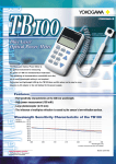
MT220 Series of Digital Manometers
– For Truly Efficient Field Calibration –
MT220
● High accuracy: ±0.01% of reading, with a maximum allowable input of 500 kPa (130 kPa-range model)
● Measurement with DCV and DCA
● Percent reading
● Error reading
● 24 V DC output
● Measurement data memory
● D/A conversion output, comparator output, and external trigger input (optional)
● GP-IB or RS-232 interfaces
● 12 V DC power supply
● Battery operation (optional)
The de facto standard of field calibrators for pressure
and differential pressure transmitters
www.yokogawa.com/tm/
... and subscribe to “Newswave,”
our free e-mail newsletter
Bulletin 7673-50E
The de Facto Standard of Field Calibrators for Pressure
and Differential Pressure Transmitters
High-Performance, High-Efficiency Field Calibration
Full Support for Higher Accuracy of Pressure/Differential Pressure Transmitters
In electric power, gas, nuclear power, oil refinery, petrochemical and pharmaceutical plants, numerous sensors
are used to measure such variables as pressure, temperature and flow rate, and to automate the process. These
sensors must be calibrated periodically to maintain product quality. However, because there are typically so many
pressure/differential pressure transmitters out in the field, the transmitters are usually calibrated in-situ. This
calibration accounts for much of plant maintenance work. Efficiency is therefore crucial to maintain uptime of
equipment and facilities.
The MT220 is a precision digital manometer for use with pressure/differential pressure transmitters and is designed
to maximize the efficiency of field calibration work.
The accuracy of pressure/differential pressure transmitters has continued to improve, from ±0.25% to ±0.1%, and
now to ±0.075%. That means the accuracy and stability of the manometers used to calibrate these transmitters
must keep pace.
The MT220 employs Yokogawa’s original silicon resonant sensor—a high precision pressure sensing device.
We’ve also set up an advanced calibration environment, including a tightly-controlled traceability system. As a
result, our calibrators feature basic accuracy as high as ±0.01%, and excellent stability. With the MT220, you can
verify the performance of even the most accurate of pressure/differential pressure transmitters, i.e. ±0.075%.
Functions Tailored to Your Calibration Work
Calibration involves inputting the same pressure level to both a calibrator and a transmitter and comparing the
transmitter output with a value measured by the calibrator. The MT220 comes with all the functions you need for
such calibration work in the plant or field. Practical functions include measuring transmitter output (1-5 V or 4-20
mA), outputting 24 V DC for driving the transmitter, and indicating the transmitter output error as a percent value.
The MT220 even has a pressure range pre-adjusted to that of transmitters.
Years of Experience in Precision Pressure Measuring Instruments
Yokogawa, a leading company with a proven track record in the field of industrial instruments and instrumentation,
also has decades of experience in pressure measurement. We’ve been developing digital manometers for more
than 20 years and have won a great many loyal customers. Our wide range of pressure measuring instruments
offer unrivalled functionality and performance.
Assured Compatibility with Earlier Models
The specifications of the MT220 are based on the earlier series of MT120 manometers to ensure compatibility;
both series also share the same communications commands.
Other Major Functions
Many other functions help you implement your specific applications successfully.
● Front Panel
Backlight key
Comparator output LED
indicator (optional)
Pressure unit selector key
Used to select from up to seven units; factory-set to kPa.
Error readout key
(%ERROR function)
Shows an error in the volt-DC or
ampere-DC reading of a pressure
measurement (transmitter output)
as a percent value.
LCD for 5.5-digit readings
(pressure measurement) and
4.5-digit readings
(measurement with DCV and
DCA functions); 4.5-digit and
3.5-digit readings, respectively,
for Model 767355.
The EL-backlight LCD presents
a clear, sharp view even in dark
places.
Parameter setting keys
Sets the measurement
conditions, communication
interface, etc.
DC power supply input terminal
Output terminal (optional)
AC power supply fuse
AC power
supply input
terminal
Communication interface
Selected from GP-IB and
RS-232.
Power line switch
D/A conversion output terminal
(optional)
Data storage keys
Up to 2,000 data items can be
stored in the internal memory.
Zero calibration key
Adjusts the zero reading to the
atmospheric pressure or
vacuum.
Pressure input connection
You can choose from three
choices of connector
configuration. The same
connection is found on the rear
panel.
Power switch
Data hold key
Trigger key
24 V DC output ON/OFF key and terminals
Used as a power supply for operating a transmitter
during field calibration work.
22
● Rear Panel
Readout digits selector keys
Turns off the LSD of a pressure
reading from the display to
avoid difficulty in reading the
value due to fluctuations in the
LSD.
Relative key
Shows the deviation from a
specified pressure
measurement.
DCV/DCA functions keys
Turn on or off the DCV/DCA
functions, or toggle between
the functions.
Percent input readout keys
• Pressure: Can be displayed as a percent with reference
to your desired full scale set point. In addition, you can
define selected pressure readings as the upper and
lower limits of a full scale.
• Volt and ampere DC: Can be displayed as a percent by
defining the 1-5 V or 4-20 mA range as the 0-100% range.
DCV/DCA measurement terminals
Greatly help reduce the field calibration work required
for pressure/differential pressure transmitters. The
current (A) terminal is protected by a built-in fuse
against overrange input levels.
Pressure input connection
3
High-Performance Products Built on Sound Technology
Automation of Pressure Measurement
D/A Conversion Output (Optional)
32.5kPa
Outputs a D/A-converted signal through the external terminal.
This feature lets you easily send measurement data to a
measuring system or a recorder.
50ms
Example of D/A Conversion Output Waveform
Comparator Output and External Trigger Input (Optional)
The comparator output provides the result of comparing an input level with preset upper and lower limits through the external
terminal. You can also apply a start-of-measurement trigger using the rising edge of an external trigger signal supplied through
the external trigger input. These features help automate your production/inspection lines of pressure-related products.
GP-IB (or RS-232) Interface—Choose When Ordering
This feature lets you read measured values into your PC or set measurement conditions from the PC. Communication is still
possible even when the MT210/210F series are operated on batteries or the DC power source.
Yokogawa Traceability System for Ensuring Top Reliability of Pressure
measurement by customers
The company is committed to controlling and maintaining the accuracy of standards installed in the standards room of its Kofu
plant.
Traceability System Chart
Japanese national standards
National Institute of Advanced Industrial
Science and Technology
Reference standards
Pressure balances
(Dead-weight pressure gauge)
Reference weights
Calibration standards
Working Standards (Digital manometers)
Products: MT220
4
Geographical Survey Institute
Acceleration of gravity
Standards room under stringent control
within the Kofu plant of Yokogawa
A Proven Track Record of Field Applications
Field Calibration of Pressure/Differential Pressure Transmitters
The MT220 can measure pressure with outstanding accuracy,
high resolution, minimal tempco, and excellent stability. It
offers a wealth of functions for field calibration, including
transmitter output measurement (DCV/DCA functions), 24-V
DC output, percent error readout, measurement data memory,
and Ni-Cd battery operation. The D/A conversion output
makes it simple to output data to a recorder or other
equipment. And of course, data output through a GP-IB or
RS-232 interface is also possible—including data output
during operation on a 12 V DC power supply or Ni-Cd batteries.
MT220
+ –
Pressure source
(e.g., handheld pump)
Pressure/differential pressure transmitter
Example of Calibration Work
Hook-up Example
Calibration System Configuration Using a Combination of MT220 and
Instrument being
Standard Pressure Source
MT220
Calibrating transmitters, pressure sensors and manometers
is easy. Simply combine the MT220 with a standard pressure
source (e.g., MC100 series) or a handheld pump (e.g., Model
BA-11). You can also automate your calibration system by
integrating your PC and relevant equipment with the system,
making it ideal for a calibration laboratory, for example.
calibrated
PC
GP-IB
24VDC
4-20 mA
or
1-5 V
Printer
Pressure-reducing
MC100-series
valve
standard pressure source
Hook-up Example
Example of System Configuration
Major Users of Yokogawa Digital Manometers (for Reference Only)
National standards institutions in Japan and abroad; institutions related to nuclear power generation; national and public
research institutions; electric-power companies; automakers and their affiliates; electric home appliances manufacturers;
precision instruments manufacturers; semiconductor and electronic components manufacturers; pharmaceutical
manufacturers; heavy electrical machinery builders; oil refinery companies and chemical and petrochemical companies;
and engineering companies.
5
Technical Data
■ Pressure-Measurement Specifications
Model
767351
Pressure type
Measurement range
(with guaranteed accuracy)
Readout range
Accuracy*6 *7
(Six months after calibration)
(Tested at 23 ±3°C, after zero calibration)
Measurement accuracy one year after
calibration (add each value to the accuracy
six months after calibration)
(Tested at 23 ±3°C, after zero calibration)
Positive pressure: 0 to 10 kPa
Negative pressure: -10 to 0 kPa
767353
-12.0000 to 12.0000 kPa
Positive pressure:
±(0.01% of reading
+0.015% of full scale)
Negative pressure:
±(0.2% of reading
+0.1% of full scale)
767355
Up to 156.000 kPa
Positive pressure:
±(0.01% of reading+3
digits) for 20 to 130 kPa
±5digits for 0 to 20 kPa
Negative pressure:
±(0.2% of reading
+0.1% of full scale)
Positive pressure:
±(0.01% of reading
+0.005% of full scale)
Negative pressure:
±(0.2% of reading
+0.1% of full scale)
Positive pressure:
±(0.01% of reading
+0.005% of full scale)
Negative pressure:
±(0.2% of reading
+0.1% of full scale)
0 to 130 kPa abs
Up to 156.000 kPa abs
±(0.01% of reading+0.005% of
full scale)
±(0.005% of full scale)
250 ms
Response time*2
Allowable input
Positive pressure: 0 to 3000 kPa
Negative pressure: -80 to 0 kPa
Up to 3600.00 kPa
±(0.01% of full scale)
767357
Absolute
Up to 840.000 kPa
Readout update interval*1
Resolution
767356
Gauge
Positive pressure: 0 to 130 kPa
Positive pressure: 0 to 700 kPa
Negative pressure: -80 to 0 kPa
Negative pressure: -80 to 0 kPa
2.5 s max.
0.0001 kPa
0.001 kPa
2.7 kPa abs to 500 kPa gaug
2.7 kPa abs to 500 kPa gauge
0.01 kPa
0.01 kPa
2.7 kPa abs to 3000 kPa gauge 2.7 kPa abs to 4500 kPa gauge
0.001 kPa
1 Pa abs to 500 kPa abs
Approx. 10 cm3
Internal volume
Zero point: ±0.0015% of full scale/°C
Zero point: ±0.001% of full scale/°C
Temperature effect
Span: ±0.001% of full scale/°C
Span: ±0.001% of full scale/°C
Effect of attitude • 90° tilt, forward or backward Zero point: ±0.1% of full scale Zero point: ±0.01% of full scale Zero point: ±0.01% of full scale Zero point: ±0.01% of full scale Zero point: ±0.01% of full scale
Span: ±2.5% of full scale
Span: ±0.2% of full scale
Span: ±0.05% of full scale
Span: ±0.01% of full scale
Span: ±0.2% of full scale
• 30° tilt, right or left
10–5cm3/s
Leak rate
Weight (main unit)
Approx. 8.5 kg
Approx. 7.0 kg
Approx. 8.5 kg
Approx. 7.0 kg
Approx. 7.0 kg
Gases and liquids (non-flammable, non-explosive, non-toxic and non-corrosive fluids)
Applicable fluids
5 to 50°C
Fluid temperature
Liquid viscosity
5 × 10⁻⁶ m2/s max.
Pressure sensor
Silicon resonant sensor
Diaphragm
Pressure sensing element
kPa only, or selection from a group consisting of kPa, kgf/cm2, mmHg and mmH2O or a group consisting of kPa, psi, inHg, inH2O, kgf/cm2, mmHg and mmH2O; specify when ordering*3)
Readout unit
Pressure input connector
Rc1/4 or NPT1/4 female-threaded or VCO1/4 male-threaded*4 (specify when ordering), located on both front and rear panels; however, simultaneous input to connections on both sides is prohibited)
Material of measurement section
Diaphragm: Hastelloy C276; flange of measurement chamber: stainless steel (JIS SUS316), Internal piping: stainless steel (JIS SUS316); O-ring: fluororubber; input connector: stainless steel (JIS SUS316)
■ Reference Information
Yokogawa’s Original Silicon Resonant Sensor (Winner of the Ohkochi Grand
Technology Prize and the Chairman's Award of the Japan Federation of Economic
Organizations (Keidanren))
Excitation terminal
Thanks to Yokogawa’s award-winning sensor, the MT220
boasts a basic accuracy as high as ±0.01%, and high
resolution. The silicon resonant sensor is also practically
immune to external effects such as temperature
variations.
Magnetic field
Detector terminal
Vibrator
Vacuum cell
Diaphragm
Vibrators
Excitation
terminal
Pressure
Detector terminal
Diaphragm chip
Structural View of Silicon Resonant Sensor
■ Pressure Unit Conversion Table
6
Pa
bar
kgf/cm2
atm
mmH2O or mmAq
mmHg or Torr
1
1 × 10⁵
9.806 65 × 104
1.013 25 × 105
9.806 65
1.333 22 × 102
1 × 10⁻⁵
1
9.806 65 × 10–1
1.013 25
9.806 65 × 10–5
1.333 22 × 10–3
1.019 72 × 10–5
1.019 72
1
1.033 23
1 × 10⁻⁴
1.359 51 × 10–3
9.869 23 × 10–6
9.869 23 × 10–1
9.678 41 × 10–1
1
9.678 41 × 10–5
1.315 79 × 10–3
1.019 72 × 10–1
1.019 72 × 104
1 × 10⁴
1.033 23 × 104
1
1.359 51 × 10
7.500 62 × 10–3
7.500 62 × 102
7.355 59 × 102
7.600 00 × 102
7.355 59 × 10–2
1
■ Common Specifications
■ DCV/DCA Function Specifications
Measurement range (with guaranteed accuracy)
Voltage
Current
0 to ±5.25 V
0 to ±21 mA
±(0.01% of reading + 2 digits) 30 days after calibration
±(0.03% of reading + 2 digits) 90 days after calibration
Accuracy
(Tested at 23 ±3°C)
±(0.05% of reading + 3 digits) 6 months after calibration
±(0.07% of reading + 3 digits) 1 year after calibration
Readout range
0 to ±6.0000 V
0 to ±24.000 mA
Maximum allowable input
30VDC
100mA
Readout unit
V
mA
Input impedance
Approx. 10 MΩ
Approx. 20 MΩ
CMRR
120 dB min.
(50/60 Hz; Rs = 1 kΩ)
—
—
NMRR
60 dB min.
(50/60 Hz)
—
—
Temperature effect
±(0.01% of reading + 2 digits) /10°C
Display
LCD (with backlight); number of readout digits: 5.5 or 4.5*5 digits
for pressure measurement and 4.5 digits for measurement with
DCV/DCA functions
Warm-up time
Approx. 5 minutes
Operating temperature/humidity ranges 5 to 40°C/20 to 80% RH (no condensation)
Altitude of operation
2000 m max.
Storage temperature range
-20°C to 60°C
Power Supply
Three-way power (AC or DC supply, or optional Ni-Cd batteries)
AC power rating
100 to 120/200 to 240 V AC, at 50/60 Hz
Allowable supply voltage range
90 to 132 V/180 to 264 V AC
Allowable supply frequency range 47 to 63 Hz
DC power rating
10 to 15 V DC
Battery pack (optional)
Ni-Cd batteries: Last approximately 6 hours in continuous
operation mode when fully charged (tested with the backlight,
DCV/DCA functions and 24-V DC output turned on).
Battery charger: Built into the MT220 main unit
Recharge time: Approx. 12 hours
Power consumption
When in pressure measurement mode: 25 VA max. for 100-V
power line; 40 VA max. for 200-V power line
When in recharge mode: 45 VA max. for 100-V power line; 65 VA
max. for 200-V power line
When in DC-powered operation: 10 VA max.
Note: The maximum allowable potential difference between any measuring terminal and the grounding
terminal is 42 Vpeak.
■ 24 V DC Output Specifications
Output voltage
24 ±1 V DC (fixed)
Output current
30 mA max. (with limiter)
Insulation resistance
20 MΩ min. at 500 V DC, between AC power supply and casing
Note: The maximum allowable potential difference between any measuring terminal and the grounding
terminal is 42 Vpeak.
Withstanding voltage
1500 V AC (50/60 Hz) for 1 minute, between AC power supply and casing
■ Data Memory Specifications
External dimensions
Main unit:
Approx. 132 mm × 213 mm × 350 mm, excluding protrusions
Battery pack (optional):
Approx. 33 mm × 182 mm × 260 mm, excluding protrusions
Weight
Main unit: See the Pressure-measurement Specifications section.
Battery pack: Approx. 2.7 kg
Accessories
Connector for DC power supply (1), rubber pads for rear foot (2),
labels for indicating measurement object, test lead (1), power
cord (1), and user's manual (1)
Memory capacity
2000 data items
■ Specifications of Communication Interfaces (choose one)
GP-IB interface
Electrical and mechanical specifications Conforms to IEEE Standard 488-1978
Functional specifications
SH1, AH1, T5, L4, SR1, RL1, PP0, DC1, DT1, C0
RS-232 interface
Transmission method
Start-stop synchronization
Transfer ratea
1200, 2400, 4800, 9600 bits/s
■ Specifications of "/DA" Option
D/A Conversion Output
Output voltage
Switchable between 0 to ±2 V and 0 to ±5 V to reflect the readout
of pressure measurement
Example of corresponding output voltages when measured with a
130-kPa gauge-pressure model set to the ±2 V range:
0 kPa = 0 V
65 kPa = 1 V
130 kPa = 2 V
156 kPa = 2.4 V
-80 kPa = -1.230 V
Output resolution
16 bits, where full scale is approximately ±125% of range
Output accuracy
(Tested at 23 ±3°C, after zero
calibration, using the D/A
conversion output terminal)
Add ±0.05% of full scale to accuracy in the Pressuremeasurement Specifications section.
Temperature effect
±(0.005% of full scale)/°C
*1 The interval of outputting data via communication is the same as the readout update interval.
*2 Conditions of response time measurement
• The response time is defined as the interval from the start of change to the time the readout
settles to within ±1% of its final value.
• The manometer under test is made open to the atmospheric pressure when it is at its full-scale
value, where the input section is under no load. In the case of absolute-pressure models, the
manometer under test is made open to the atmospheric pressure at a scale value of 0.
• Measurement is performed using the D/A conversion output.
*3 All models are factory-set to kPa.
*4 VCO is a registered trademark of Swagelok Company. A conversion connector is attached.
*5 4.5/3.5 digits for Model 767355.
*6 Yokogawa’s pressure standards accuracy is excluded.
*7 Long term stability of zero point is excluded.
■ External Dimensions
Main unit
Unit: mm
Rear View
(Equipped with RS-232 connector)
Output update interval
Approx. 2 ms
Response time
Same as the response time specified in the Pressure-measurement Specifications section.
Output resistance
0.1 Ω max.
Load resistance
1 kΩ min.
13
213
13
327
23
(Equipped with GP-IB connector)
27
Operation
HIGH = 1, if measured value > upper limit
IN = 1, if upper limit ≥ measured value ≥ lower limit
LOW = 1, if measured value < lower limit
BUSY = 1, if there is a transition in the output signal
An LED lamp on the display corresponding to HIGH, LOW or IN
comes on.
Signal level
TTL
21
HIGH, IN, LOW, BUSY
Battery pack
33.5
Output signal
132
Comparator Output
183
260
Input level
TTL
Operation
A start-of-measurement trigger is applied at a falling edge when
the high-state level of an external signal is input with the HOLD
function enabled. At the moment of triggering, the LED lamp on
the front panel comes on.
10.3
External Trigger
Unless otherwise specified, the tolerance is ±3%; for dimensions smaller than 10 mm, however,
the tolerance is ±0.3 mm.
7
Models and Suffix Codes
Related Products
■ Main Units
MT210/210F Digital Manometers
Product
Model Suffix Code
767351
———
MT220
767353
———
series of
767355
———
digital
———
manometers 767356
767357
———
–U1
–U2
kPa,
switchable to kgf/cm2, mmHg or mmH2O
–U3
kPa, switchable to psi, inHg, inH2O,
kgf/cm2, mmHg or mmH2O
Pressure unit
Communication interface
Pressure I/O connection
Power cord
Remarks
10 kPa-range, gauge-pressure model
130 kPa-range, gauge-pressure model
700 kPa-range, gauge-pressure model
3000 kPa-range, gauge-pressure model
130 kPa-range, absolute-pressure model
kPa
–C1
–C2
–P1
–P2
–P3
–D
–F
–H
–R
–Q
Option
/DA
GP-IB
RS-232
Rc 1/4
NPT1/4 female-threaded
VCO 1/4 male-threaded*
UL/CSA standard
VDE standard
GB standard
AS standard
BS standard
■ Optional Accessories
Model Suffix Code
269913
——
269914
——
B9320ND ——
B9984BY
——
B9984BW ——
B9310ZH
——
G9612BG ——
G9612BJ
——
G9612BW ——
Remarks
Ni-Cd batteries for MT210/220 series
A kit of three Ni-Cd batteries for the 269913 battery pack
For use with MT210/220 series
For use with φ4 × φ6 PVC tubing (for “-P1” option)
For use with φ4 × φ6 PVC tubing (for “-P2” option)
For use with φ4 × φ6 PVC tubing
JIS; R1/4-to-Rc1/8
ANSI; R1/4-to-NPT1/4 female thread
ANSI; R1/4-to-NPT1/8 female thread
■ Carrying Case
Picture of B9320ND carrying case
■ Adapting Connectors for Input Section
Connector assembly kit
B9984BW
MT10 Mini-manometer
● Highly reliable design based on silicon resonant
sensor
● Compact
● High accuracy: ±(0.04% of reading + 0.03% of full
scale) for 130 kPa-range model
● Three choices of pressure range: 130, 700 and
3000 kPa
● Simple operation
● Data hold function
● RS-232 interface
D/A conversion output, comparator output
and external trigger input
* VCO is a registered trademark of Swagelok Company.
Product
Battery pack
Ni-Cd batteries
Carrying case
Connector assembly kit
Connector assembly kit
Simplified connector assembly kit
Adapting connector
Adapting connector
Adapting connector
● High accuracy: ±0.01% of reading
● Maximum allowable input: 500 kPa
(130 kPa-range model)
● A wide range of pressures, from low
differential pressure of 1 kPa to high
gauge pressure of 3000 kPa
● Selection from three measurement
modes: normal speed, medium speed
and high speed (MT210F series)
● D/A conversion output, comparator
output, and external trigger input
(optional)
● GP-IB and RS-232 interfaces
● 12-V DC power supply
● Battery operation (optional)
MC100 Pressure Standard
● High accuracy: ±(0.05% of full scale)
● Excellent stability of operation based
on silicon resonant sensor
● Two choices of pressure ranges: 25
and 200 kPa
● Output divider function for generating
fractions of a pressure setpoint, to a
maximum resolution of 1/20
● Output autostep function
● Output sweep function
● Offset monitor function
CA71 Handy Calibrators
● Source and measure operations at the
same time. DC Voltage, DC Current,
Resistance, Thermocouple (TC),
Resistance Temperature Detector (RTD),
Frequency, Pulse).
● AC voltages, including supply voltage,
can be measured.
● Includes a wide array of additional
functions.
● Easy operation.
● Compact size and Lightweight.
Simplified connector
assembly kit
B9310ZH
Adapting connector (JIS) Adapting connector (ANSI) Adapting connector (ANSI)
G9612BG
G9612BW
G9612BJ
NOTICE
● Before operating the product, read the instruction manual thoroughly for
proper and safe operation.
● If this product is for use with a system requiring safeguards that directly
involve personnel safety, please contact the Yokogawa sales offices.
YOKOGAWA ELECTRIC CORPORATION
Communication & Measurement Business Headquarters /Phone: (81)-422-52-6768, Fax: (81)-422-52-6624
E-mail: [email protected]
YOKOGAWA CORPORATION OF AMERICA Phone: (1)-770-253-7000, Fax: (1)-770-251-6427
YOKOGAWA EUROPE B.V.
Phone: (31)-88-4641000, Fax: (31)-88-4641111
YOKOGAWA ENGINEERING ASIA PTE. LTD. Phone: (65)-62419933, Fax: (65)-62412606
Subject to change without notice.
[Ed : 03/b] Copyright ©2001
Printed in Japan, 906(KP)
MS-17E