1
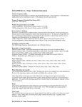
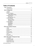
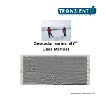
MINI SOUNDER
USER MANUAL
D101-04917
Revision 1.01
May 2009
Knudsen Engineering Limited
10 Industrial Road
Perth, Ontario, Canada
K7H 3P2
Phone: 613-267-1165
Fax: 613-267-7085
www.knudsenengineering.com
[email protected]
CONTENTS
1
INTRODUCTION . . . . . . . . . . . . . . . . . . . . . . . . . . . . . . . . . . . . . . . . . . . . . . . . . . . . . . . . . . . . . . . . .
1.1
About this manual . . . . . . . . . . . . . . . . . . . . . . . . . . . . . . . . . . . . . . . . . . . . . . . . . . . . . . . . . .
1.2
Technical Support . . . . . . . . . . . . . . . . . . . . . . . . . . . . . . . . . . . . . . . . . . . . . . . . . . . . . . . . . .
1.3
Unpacking Shipment . . . . . . . . . . . . . . . . . . . . . . . . . . . . . . . . . . . . . . . . . . . . . . . . . . . . . . . .
2
DESCRIPTION . . . . . . . . . . . . . . . . . . . . . . . . . . . . . . . . . . . . . . . . . . . . . . . . . . . . . . . . . . . . . . . . . . . 4
2.1
System Overview . . . . . . . . . . . . . . . . . . . . . . . . . . . . . . . . . . . . . . . . . . . . . . . . . . . . . . . . . . . 4
2.2
Physical Characteristics . . . . . . . . . . . . . . . . . . . . . . . . . . . . . . . . . . . . . . . . . . . . . . . . . . . . . . 4
3
INSTALLATION . . . . . . . . . . . . . . . . . . . . . . . . . . . . . . . . . . . . . . . . . . . . . . . . . . . . . . . . . . . . . . . . .
3.1
System Overview . . . . . . . . . . . . . . . . . . . . . . . . . . . . . . . . . . . . . . . . . . . . . . . . . . . . . . . . . . .
3.2
Software Installation . . . . . . . . . . . . . . . . . . . . . . . . . . . . . . . . . . . . . . . . . . . . . . . . . . . . . . . .
3.3
Connector Panel Overview . . . . . . . . . . . . . . . . . . . . . . . . . . . . . . . . . . . . . . . . . . . . . . . . . . . .
3.3.1
Input Power . . . . . . . . . . . . . . . . . . . . . . . . . . . . . . . . . . . . . . . . . . . . . . . . . . . . . . . .
3.3.2
Power Switch . . . . . . . . . . . . . . . . . . . . . . . . . . . . . . . . . . . . . . . . . . . . . . . . . . . . . . .
3.3.3
Power Indicator . . . . . . . . . . . . . . . . . . . . . . . . . . . . . . . . . . . . . . . . . . . . . . . . . . . . .
3.3.4
Transmit (TX) Output . . . . . . . . . . . . . . . . . . . . . . . . . . . . . . . . . . . . . . . . . . . . . . . .
3.3.5
USB Interface . . . . . . . . . . . . . . . . . . . . . . . . . . . . . . . . . . . . . . . . . . . . . . . . . . . . . . .
3.4
System Connection . . . . . . . . . . . . . . . . . . . . . . . . . . . . . . . . . . . . . . . . . . . . . . . . . . . . . . . . . .
3.4.1
Peripherals . . . . . . . . . . . . . . . . . . . . . . . . . . . . . . . . . . . . . . . . . . . . . . . . . . . . . . . . .
3.4.2
Data Logging . . . . . . . . . . . . . . . . . . . . . . . . . . . . . . . . . . . . . . . . . . . . . . . . . . . . . . .
3.5
Transducer Installation . . . . . . . . . . . . . . . . . . . . . . . . . . . . . . . . . . . . . . . . . . . . . . . . . . . . . .
3.5.1
Over-the-Side . . . . . . . . . . . . . . . . . . . . . . . . . . . . . . . . . . . . . . . . . . . . . . . . . . . . . . .
3.5.2
Through Hull . . . . . . . . . . . . . . . . . . . . . . . . . . . . . . . . . . . . . . . . . . . . . . . . . . . . . . .
3.5.3
Sea Chest . . . . . . . . . . . . . . . . . . . . . . . . . . . . . . . . . . . . . . . . . . . . . . . . . . . . . . . . . .
5
5
5
5
5
5
5
6
6
6
6
6
6
6
7
7
4
SYSTEM OPERATION . . . . . . . . . . . . . . . . . . . . . . . . . . . . . . . . . . . . . . . . . . . . . . . . . . . . . . . . . . . .
4.1
Factory Setup . . . . . . . . . . . . . . . . . . . . . . . . . . . . . . . . . . . . . . . . . . . . . . . . . . . . . . . . . . . . . .
4.2
Basic Controls . . . . . . . . . . . . . . . . . . . . . . . . . . . . . . . . . . . . . . . . . . . . . . . . . . . . . . . . . . . . .
4.2.1
Shallow Water Hints . . . . . . . . . . . . . . . . . . . . . . . . . . . . . . . . . . . . . . . . . . . . . . . . .
4.2.2
Deep Water Hints . . . . . . . . . . . . . . . . . . . . . . . . . . . . . . . . . . . . . . . . . . . . . . . . . . . .
8
8
8
8
8
5
TROUBLESHOOTING . . . . . . . . . . . . . . . . . . . . . . . . . . . . . . . . . . . . . . . . . . . . . . . . . . . . . . . . . . . . .
5.1
Power Indicator is Off . . . . . . . . . . . . . . . . . . . . . . . . . . . . . . . . . . . . . . . . . . . . . . . . . . . . . . .
5.2
No Output to Transducer . . . . . . . . . . . . . . . . . . . . . . . . . . . . . . . . . . . . . . . . . . . . . . . . . . . . .
5.3
No Connection to PC . . . . . . . . . . . . . . . . . . . . . . . . . . . . . . . . . . . . . . . . . . . . . . . . . . . . . . . .
9
9
9
9
D101-04917-Rev1.01
May 2009
3
3
3
3
2 of 10
1
INTRODUCTION
1.1
About this manual
This manual describes the basic setup and operation of the Mini Sounder.
1.2
Technical Support
For technical support or to report problems please contact your local representative or:
Technical Support
Knudsen Engineering Limited
10 Industrial Road
Perth, Ontario
K7H 3P2
Voice:
Fax:
E-Mail:
WebSite:
1.3
(613) 267-1165 8:30 am to 5:00 pm E.S.T. Core Hours
(613) 267-7085
[email protected]
http://knudsenengineering.com/
Unpacking Shipment
The Mini Sounder is securely packed in a plastic shipping/storage case. In the standard shipment will be the
following items:
!
!
!
!
!
Mini Sounder Echosounder
DC power cable
Transducer cable connector(unless already installed on transducer)
Waterproof USB cable
SounderSuite Software CD-ROM
D101-04917-Rev1.01
May 2009
3 of 10
2
DESCRIPTION
2.1
System Overview
The Mini Sounder is a portable, low cost, entry level system ideal for shallow water to mid-depth surveys. It is a
single channel system that the user can configure to any frequency between 24kHz and 210kHz allowing water
depths from 15cm up to 1000M (transducer dependant).
Multiple Mini Sounder systems allow the user the flexibility of having a dual channel system (ex 28/200kHz) on
one day for sub bottom tracking and two single channels systems the next day for multiple vessel surveys.
2.2
Physical Characteristics
Outline drawings showing external dimensions, locations of connectors and controls, and location and
specification of mounting points are located later in this manual. A summary of significant dimensions and
weights of the Echosounder follows:
Length
Width
Height
Weight
D101-04917-Rev1.01
257 mm
158 mm
89 mm
less than 3kg
May 2009
4 of 10
3
INSTALLATION
3.1
System Overview
The Mini Sounder is a “black box” echosounder that utilizes a PC to allow the user to control all system
parameters, manage peripherals, record entire echogram data, as well as internal and external data logging. The
communication link from the Mini Sounder to the PC is via USB (full speed 2.0).
3.2
Software Installation
Once installed in the CD-ROM drive of your PC the SounderSuite-USB installation wizard will guide the user
through the installation. For a more detailed explanation of the entire software installation please refer to the
following manual:
SounderSuite - USB Windows Installation and Firmware Upgrades (part number D101-04383)
3.3
Connector Panel Overview
3.3.1
Input Power
The Mini Sounder needs to be powered from a DC source. The input voltage range is 12-30 VDC (nominal
24VDC). The power consumption of the Mini Sounder at startup is 20W with an average operating consumption
between 15W and 18W.
3.3.2
Power Switch
When the power switch is placed in the “1" position it will pass the input voltage to the internal modules. When it
is placed in the “0" position, power to the internal modules will be terminated. The power switch also has a built in
circuit breaker for protection.
3.3.3
Power Indicator
This green indicator LED will illuminate when the proper input voltage has been applied to the Mini Sounder and
transferred to the internal modules.
D101-04917-Rev1.01
May 2009
5 of 10
3.3.4
Transmit (TX) Output
The TX Output connection transfers the high voltage transmit output signal to the transducer as well as the return
echo to the echosounder. CAUTION: Make sure that the Mini Sounder is not transmitting while connecting or
disconnecting the transducer to the Tx Output connection.
3.3.5
USB Interface
The USB interface provides communication from the Mini Sounder to the PC. It is a full speed 2.0 (12Mbps)
connection. The connection is a waterproof IP68 “B” type but will mate with any standard USB cable.
3.4
System Connection
3.4.1
Peripherals
All peripherals are connected directly to the PC and the setup for each is via the EchoControl Client software
application.
3.4.2
Data Logging
Same as the peripherals, any connection to an external data logger is done through the PC. There also is the
capability to run the data logging package on the same PC that your EchoControl software is operating on.
3.5
Transducer Installation
The correct transducer installation is essential to maintain good system performance. Three are three common
types of transducer installations:
1) Over-the-side
2) Through Hull
3) Sea Chest
3.5.1
Over-the-Side
D101-04917-Rev1.01
May 2009
6 of 10
The method of mounting the transducer over the side of the boat is primarily used for temporary installations. This
usually entails the transducer mounted to the end of a pole that is fastened to the side of the boat. The majority of
the transducers that are sold by Knudsen Engineering Limited have the option to be purchased with a mounting
adapter. The adapter provides a small mounting stem made of a 1-1/4" aluminum pipe with a standard pipe thread.
The longer pipe and the means to fasten it to the boat are not provided as they change with every installation. It is
very important that the transducer will be completely submerged below the water surface at all times.
3.5.2
Through Hull
A more permanent means of mounting the transducer is through the hull. This will require modifications to be
made to the hull of the boat. The face of the transducer will become the “wet end” in direct contact with the water
and the cable end of the transducer will become the “dry end” inside the hull of the boat. The location of where the
transducer goes through the hull has to be selected to prevent any type of aeration coming in contact with the
transducer face. Any modifications that are to be done to the boat to install the transducer through the hull should
be made by a qualified individual.
3.5.3
Sea Chest
Another permanent means of transducer installation in using a sea chest. The chest is located on the inside of the
hull and the transducer transmits and receives either through the hull itself or through an acoustic window. The sea
chest will need to be filled with water and may need a stand pipe to provide proper pressure to the transducer to
avoid cavitation. The following illustration is an example of a sea chest transducer installation.
D101-04917-Rev1.01
May 2009
7 of 10
4
SYSTEM OPERATION
Your PC will automatically recognize the Mini Sounder upon power up. The SounderSuite installation CD will
have installed applications shortcuts to the desktop of the PC. The EchoControl Server application needs to be
started first and once running a “K” will appear in the task bar. After the EchoControl Server is running the
EchoControl Client application can be started. NOTE : Running EchoControl Client will auto-run EchoControl
Server. For a complete explanation on the operation of the EchoControl Server and EchoControl Client please
refer to the following manual:
SounderSuite - USB EchoControl Client (part number D101-04380)
4.1
Factory Setup
The Mini Sounder features a frequency agile channel that the user can configure to any frequency between 24 and
210kHz. The Mini Sounder’s operating frequency will be preset at the factory to match a specific transducer, either
supplied with purchase or requested by purchaser.
4.2
Basic Controls
For a complete explanation of all EchoControl Client controls please refer to the following manual:
SounderSuite - USB EchoControl Client (part number D101-04380)
Some of the basic controls that the user will need to understand to operate the Mini Sounder are Tx Power, Gain,
Pulse Length, Range, Phase, and Tx Blanking.
The Tx Power, Gain, and Pulse Length directly affect the strength of the output signal and thus the return echo.
There are four power settings each approximately 25% of the configured total output power. The Gain can be
selected manually or automatically (recommended). Shorter pulse lengths are to be used in shallow waters and
longer pulse lengths in deeper water. Longer pulse lengths may be used in shallow water if the user is sub-bottom
profiling.
The Range and Phase settings will tell the echosounder what the extents of the search window are. The Range
determines the size of the search window and the Phase determines where in the water column to search. For
example: (assuming Meters as units) Range 100 Phase 1
The search window will be from 0 to 100M. If the Phase changes to 2 the search window will shift down the water
column and now be 50-150M. The same amount of information (100M) remains as the Range did not change.
There is an AutoPhase control that will allow the echosounder to change to the proper phase as the bottom
approaches either extent of the search window.
The Tx Blanking setting allows the user to block out any transducer ringing near the surface that may appear as a
return and possibly confuse the system’s bottom tracking. The Tx Blanking can be set by observing the amount of
ringing present on your data when in a primary search window (0-10, 0-50, etc).
4.2.1
Shallow Water Hints
For operation in shallow water set the Power setting to 1 or 2. Set the Gain to AGC (Automatic Gain Control) and
set the pulse length to its lowest setting. Make sure that the Tx Blanking settings is at a level that will function in
your desired water depth. Set your Phase to 1 and your range to a level just larger than your desired water depth.
4.2.2
Deep Water Hints
D101-04917-Rev1.01
May 2009
8 of 10
For operation in deeper water you need to increase your Power to a level of 3 or 4. Leave the Gain set to AGC and
increase your pulse length. The Tx Blanking setting should also be increased as the higher power and longer pulse
lengths will increase the transducer ringing.
5
TROUBLESHOOTING
5.1
Power Indicator is Off
Confirm proper input voltage applied to echosounder. If the input is okay then connect to PC to confirm operation.
It may be that the LED has failed. If problem continues, contact Knudsen Engineering Limited.
5.2
No Output to Transducer
Confirm that the proper transducer has been connected to the echosounder. Then check the transducer cable
for any bends, breaks, or other visible damage.
5.3
No Connection to PC
The Mini Sounder will be automatically recognized by Windows upon successful communication. If the Power
Indicator is ON but the system is not recognized by the PC then first try changing USB cables and then try a
different USB port on the PC. If the problem continues, contact Knudsen Engineering Limited.
6
CABLE CONNECTIONS
Input Power
Pin A: + Vdc
Pin B: - Vdc
Mating Cable End
Manufacturer: LEMO
Part Number: FGG.2B.302
Bulkhead front view
Transmit Output
Pin A: Out +
Pin B: Out Pin C: Shield
Mating Cable End
Manufacturer: LEMO
Part Number: FGG.3B.303
Bulkhead front view
D101-04917-Rev1.01
May 2009
9 of 10
USB
Pin 1: Power
Pin 2: Data +
Pin 3: Data Pin 4: Shield
Mating Cable End
Manufacturer: Bulgin
Part Number: PX0840
D101-04917-Rev1.01
May 2009
10 of 10