1
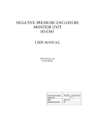
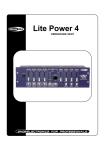
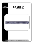
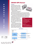
Commercial and Residential Turntables
Motion Control User Manual
Model MC-1
Introduction
The control system for the Carousel Turntables offers four modes of operation:
1. Manual
2. Camera
3. Preset
4. Program
These functions can be accessed via a built-in HTML (web) server using a standard web browser
such as Internet Explorer or Netscape Navigator, from user-supplied buttons and switches via an
accessory port, or using an optional built-in touchscreen terminal.
The main menu of the system is shown below:
In addition to selecting one of the four available operation modes, the main menu also offers the
Setup menu, where system parameters such as the current date and time, and the network
address of the system can be monitored and adjusted.
Buttons are displayed along the left side of the HTML and touch screen versions allowing quick
jumps to each mode (top-to-bottom: Manual, Camera, Preset, Program) or back to this main
screen via the lower “Menu” or “M” button.
Control Systems User Manual V1.0
Carousel USA
2
Manual Mode
Manual mode offers the user the ability to simply rotate the table at a speed of their choosing.
The system will begin to rotate the table when the right or left arrow is pressed on the screen
below. This screen is available via HTML, or will be shown on the touchscreen if that option was
chosen. The “X” button appears as soon as a move is started, and will cause the table to stop
rotating when it is pressed.
The speed graph in the lower right-hand corner of the screen adjusts the rotational speed during
manual mode.
If a digital input has been assigned to the jog left or jog right function, those inputs will take priority
over any other action and will cause this page to be displayed and the table to rotate until the
inputs switch off.
The “Mark” button will teach the system that the current position of the table is zero, which is used
as a reference for preset and programmed moves.
NOTE: Changing the zero position of the table will change all preset and programmed positions.
Control Systems User Manual V1.0
Carousel USA
3
Camera Mode
Camera Mode operates much like Jog Mode except that the user may specify how often to provide
a signal to an external camera or other device.
As shown below, the Camera Mode screen has “Go”, “Stop” and speed controls as well as a field
for the Shutter Interval. Use this field to enter the number of degrees desired between shutter
triggers. For instance, if the value of 3 was entered here, the system will send a shutter signal to
the camera every three degrees.
There is no built-in stop for this function—it will continue to run and issue shutter commands until
stopped.
Digital inputs may be assigned to start and stop camera mode, in which case these inputs will take
precedence over any screen-selected function.
The shutter command signal is given on the red and orange wires of connector J4. This is a
transistor capable of switching 5-30VDC @ 12W.
Control Systems User Manual V1.0
Carousel USA
4
Preset Mode
Preset Mode is used to position the turntable in one of five preset positions. These positions may
be chosen or edited via HTML or the touchscreen. The user may also assign digital inputs to any or
all of these preset positions. A signal on an assigned digital input will supersede any choices made
over HTML or on the touchscreen.
Pressing the Edit Preset button opens a screen that allows each of these five presets to be
defined.
On the Edit Presets screen, five tabs are
presented, each representing one of the five
presets. For each, the user may specify
whether the turn is to the right or to the left, the
size and speed of the move and whether the
measurement of the turn is relative to the
staring position or in absolute terms.
A relative move of 30° will increment the
turntable that amount every time the command
is issued.
An absolute move of 30° will move the table 30° from the zero position. If multiple commands of
this type are issued, no further action after the first will be seen as the turntable will already be at
30°.
Control Systems User Manual V1.0
Carousel USA
5
Program Mode
Program Mode provides a way for the user to have up to five moves start automatically based on
the day of the week and the time of the day. These moves could be as simple as rotating 90°
every half hour, or turning 180 degrees every day at midnight. Multiple programs can be set to
overlap to create a wide variety of move profiles.
The Program Mode Screen shows the settings for all the programs at a glance. Pressing the Edit
Program button opens a screen that allows each of the five programs to be edited.
On the Edit Timer Programs screen, four tabs
are presented each representing one of the four
programs. For each, the user may specify the
days of the week and the times that the program
should run, the repeat interval during that time,
and the move profile.
Selecting “Once” will cause the program to run
only once… it will not be repeated.
Selecting “Repeat” will cause the program to run
any time the current system time is between the
Start and Stop times.
The “Repeat Every” field specifies how often during the interval defined by the Start Time and Stop
Time the program should run. For example, a car showroom might program a move to occur every
15 minutes between 11 AM and 9 PM. Eleven AM would be the start time, nine PM the stop time,
and the “Repeat Every” field would be set to 15 minutes. If the user wanted the turntable to run
continuously, program 360º move repeating every 00:00:00 seconds.
Control Systems User Manual V1.0
Carousel USA
6
Setup
The Setup Area is divided into three tabs: System, Network and Inputs.
The System Tab allows you to set the day of the week and the time of day. For your convenience,
you can use the Mark button to set the current position of the table to zero. This is the same
function as that found on the Manual Mode screen. Keep in mind that changing the zero point will
change all programmed absolute moves and presets.
The Network Tab shows the MAC ID of your
unique controller. Your systems administrator
can use this MAC ID to help determine the IP
address of a HTML-only controller if the default
address is changed and then lost.
The IP, Netmask, and Gateway fields can all
be adjusted to suit the requirements of any
network. No changes are accepted here until
the Commit button is pressed. Keep in mind
that if you are accessing the unit over the
network, you will have to enter the new
address into your browser after you make this
change!
Control Systems User Manual V1.0
The factory default network settings are shown above.
Carousel USA
7
Setup- Cont.
The final tab of the Setup Area allows you to define the functions you wish associated with the
available digital inputs.
The Carousel controller provides up to five inputs that can be defined as shown. Once an input is
defined, when it is “true” that function will be performed regardless of any other activity being
commanded from the screen.
The inputs for Cam On and Cam Off will cause camera mode to start and stop, respectively.
Turn Left and Turn Right initiate jog mode at the speed commanded on the Jog Screen.
Presets 1 – 5 will cause the turntable to move to that specific preset position.
An input on the Mark 0 command will reset the current position indicator to zero.
Control Systems User Manual V1.0
Carousel USA
8
Physical Interface
There are six connections to the Carousel Turntable Controls: Power, Ethernet, Encoder, Utility
I/O, Proximity Switch, and VFD.
The incoming power is factory configured for 115VAC with a US-standard 3-pin straight plug. The
controls themselves will accept 100-230VAC power, and will draw under 3 amps at 115VAC.
The Ethernet connection is provided via sealed RJ45 connector. This is a standard 10 Base T/100
BASE-TX Ethernet connection where the RJ45 is wired as a NIC (network interface card). A
crossover cable will be required to connect this directly to a personal computer, or it may be
connected to a router via a straight cable. If the controls will be placed in a damp location,
purchase the sealed mating connector from Bulgin (PN: PX0837).
The Encoder cable connects to the supplied sensor. This sensor reports the current table position
back to the control system.
The Utility connector provides auxiliary power, digital inputs and camera trigger outputs. A 24VDC
power source is provided on pin 2 (brown - positive) and pin 7 (blue-common) of connector J4. Up
to ½ amp may be drawn from this connector for input switching, shutter control, and any other
auxiliary functions that the user may desire. Digital inputs are made by routing the 24VDC from pin
2 back into pin 1, 3, 4, 5, and 6:
User Input 1
Pin 1
White
User Input 2
Pin 3
Green
User Input 3
Pin 4
Yellow
User Input 4
Pin 5
Grey
User Input 5
Pin 6
Pink
Take care not to short the positive dc supply on pin 2 to ground. If this occurs, the internal circuit
breaker will have to be reset in the controller.
There are also digital outputs on connector J4 to serve as the camera trigger. Pin 8 (red) connects
to the common power line feeding all four outputs. These are sourcing outputs capable of switching
5-30VDC at up to 12W. If your remote shutter trigger supplies its own power that is within this
range, connect the positive side to Pin 8. If you would like the system to provide a 24VDC signal to
activate the trigger, jumper pin 2 of connector J4 to pin 8. Although there are four unique outputs
on the controller, they are factory programmed to all act simultaneously for shutter control. These
outputs will be found on pins 9-12 (orange, tan, black and violet) on connector J4.
Here is a comprehensive description of connector J4:
Pin
Color
Function
Pin
Color
Function
1
White
User Input 1
7
Blue
Auxiliary Power Common
2
Brown
Auxiliary Power, +24VDC
8
Red
Shutter Power In
3
Green
User Input 2
9
Orange
Shutter Output
4
Yellow
User Input 3
10
Tan
Shutter Output
5
Grey
User Input 4
11
Black
Shutter Output
6
Pink
User Input 5
12
Violet
Shutter Output
Control Systems User Manual V1.0
Carousel USA
9
Physical Interface- Cont.
The Proximity Switch input is used for automatically zeroing the turntable in some applications.
The VFD connection allows the system controller to issue move commands to the motor controller.
The ten circuits of this connector are shown below:
Pin 1
White
VFD Faulted
Pin 2
Brown
VFD OK
Pin 3
Green
System ground
Pin 4
Yellow
VFD Running
Pin 5
Grey
DC control circuit common
Pin 6
Pink
Run Forward
Pin 7
Blue
Run Reverse
Pin 8
Red
Reset Fault
Pin 9
Orange
Analog speed command 0-10VDC
Pin 10 Tan
Analog speed command common
Control Systems User Manual V1.0
Carousel USA
10
Electrical Schematics
Control Systems User Manual V1.0
Carousel USA
11
Electrical Schematics – Cont.
Control Systems User Manual V1.0
Carousel USA
12
Physical Layout
Control Systems User Manual V1.0
Carousel USA
13
Physical Dimensions
Control Systems User Manual V1.0
Carousel USA
14
2135 Huntington Drive, Suite 101
San Marino, California 91108
Toll Free (866) 796-5975