1
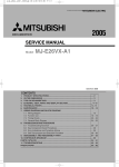
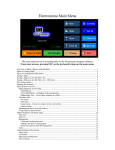
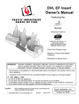
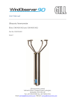
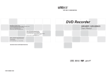
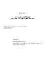
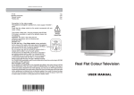
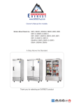
PCB0001C-01-BHP-PDII0914
Comfort Window™
Electronic Digital Thermostat
Comfort Control System
USER MANUAL &
QUICK-START GUIDE
I. Feature Summary
•
ComfortWindow Technology
•
Internet control with compatible WiFi™
network & Webpage/Smart-Phone App
•
Save on Electricity w/ Hidden Comfort
Regions and Economizer Control
•
Extra Comfort System (“Free Cooling /
Heating” w/ Economizer)
•
Convenient Interface (1-Touch Overrides
& Graphical Program Schedule)
•
Humidifier Control, Auto-Dehumidification
•
Built-in Ventilation Controls
•
High Resolution Color Touch-screen LCD
(18 bit color, 320x240, 3.5”)
•
Compatible with most HVAC Systems
•
Remote Indoor Temp Measurement
•
Outdoor Temp/Humidity Sensor &
Display
•
Armchair Programming Option
Table of Contents:
I. Feature Summary ........................1
II. Introduction...................................1
III. Compliance Information................2
IV. Quick-start Guide.........................8
V. Feature Description....................21
VI. Wiring Guide.............................29
Figure 1: Comfort Window
II. Introduction
Comfort Window is the next generation in smart
thermostat design. With innovative energy
efficient technology, Comfort Window saves in
electricity costs; and with a full color touchscreen LCD, Comfort Window presents a
modern and elegant look to fit in with any décor.
Comfort Window not only controls temperature,
it also controls humidity. With ComfortWindow
technology, users can see at a glance whether
their home is within their own personalized
window of comfort, taking into account humidity.
Comfort Window can also cool or heat their
home even further into their window of comfort
for free by utilizing outdoor air to cool or heat the
home when it is possible to do so. Not only
does this create a more comfortable
environment, it also lowers total compressor runtime significantly, thus reducing electric bills and
lowering the home's total carbon footprint.
With a comprehensive array of output controls,
internet control via smart-phone apps, and
outdoor temperature and humidity measurement
capability, Comfort Window is truly versatile.
www.yourcomfortwindow.com
[email protected]
Copyright © 2014
1 of 29
PCB0001C-01-BHP-PDII0614
► Using the provided screws and drywall anchors,
III. Quickstart Guide
mount the wall-plate to the wall.
► Adjust the angle of the wall-plate utilizing the
1. Record current wiring colors/functions
slack given in each of the holes for each screw.
► In order to properly connect wires from a preexisting thermostat to Comfort Window's screw
3. Connect thermostat wire to wall-plate
terminals, it is important to know what color
wires were connected to what functions on your
► For single compressor, single heater
existing thermostat. If the wiring colors are not
installations (non-Heat Pump), wire the
easily distinguishable, label each wire with its
thermostat as shown in Figure 3, according to
current function.
Chart 1. For any other HVAC configuration,
please refer to the Wiring Guide (Section 5).
► While there are some industry-wide coloring
► If a ground wire has not already been pulled to
conventions, some thermostat makers do not
follow these conventions; it is also possible that
the thermostat's location, first see if there are
whoever installed any previous wiring may not
any unused thermostat wires that you can use
have followed these conventions.
for Common (C). Otherwise, it will be necessary
to run an 18 GUAGE ONLY wire down the wall
*
*Caution! It is very important to be careful
that the existing wires do not fall down into the
hole in the wall.
and feed it through the hole to the wall-plate.
Chart 1: Wiring Configuration for Single
Compressor, Single Heater Installations
2. Turn off Electricity & Install Wall-plate
Screw
Terminal
Number
0
1
2
3
► ALWAYS turn off electricity to the HVAC system
at the breaker box before connecting wiring and
before connecting thermostat to the baseplate.
4
5
6
7
15
Connect To
Jumper to 1
Jumper to 4
Jumper to 3
Jumper to 4
Compressor
Transformer
+24VAC
Compressor Control
Fan Control
Heat Control
-24VAC (Ground)
Std.
Function Wire Color*
PWR
RC2
RH2
RH1
N/A
Red
Red
Red
RC1
Red
Y
G
W
C
Yellow
Green
White
Brown/Black**
**Note: Brown or Black are the most common
colors for 24VAC ground; however, white and
blue are also frequently used.
*
*Caution! While there are some industry-wide
color-coding conventions, some thermostat makers
do not follow these conventions, so it is imperative to
record the previous configuration (both color and
function) so the correct wire can be connected to the
appropriate location on Comfort Window's wall-plate.
Figure 2: Wallplate
3 of 24
PCB0001C-01-BHP-PDII0614
and black wires coming from the RITS sleeve
rather than the red, yellow, and black wires that
may be in the wall already for thermostat
control. Connecting the red, black or yellow
thermostat wire to pins 16, 17, or 19 can
permanently damage the thermostat and/or
remote temperature sensor.
*
*Caution! Only AFTER connecting
thermostat to baseplate should you
reconnect electricity to the HVAC system and
thermostat.
Figure 3: Single Compressor, Single Heater Wiring
5. Install Thermostat onto Wall-plate
► Slide thermostat through the keyed slots on
each side of the wall-plate, mating the pins with
the receptors until it rests flush with the wall *
4. Install Remote Indoor Sensor
► First, you must install the remote indoor sensor.
Drill a 3/16th inch hole ~5 inches below the
thermostat. Feed the stripped end of the indoor
temperature sensor wire through the hole,
angling upwards, and fish the wires out of the
hole in the wall-plate*. Or, route the remote
indoor sensor to the location in the house you
Figure 4: Thermostat to Wall-plate Installation
wish to measure temperature. Connect sensor
*
wires to wallplate according to Chart 2 and
Figure 3.
*Note: If you are unable to fish the indoor
sensor wire out of the hole in the wall under the
wall-plate, connect the sensor wires to the wallplate and simply drop the remote sensor into
the wall cavity to measure your home's internal
temperature.
Chart 2: Wiring Configuration for Remote
Indoor Temperature Sensor
*Caution! Incorrectly mating the thermostat
to the baseplate can potentially cause
permanent damage to the thermostat or to the
remote temperature sensor.
Only AFTER
thermostat is connected should you reconnect electricity to the HVAC system &
thermostat.
6. Re-Apply Power & Configure Thermostat
► Reconnect electricity at the breaker box. If your
system is something other than a Single
Compressor / Single Gas Heater * system or if
you have any extra outputs other than those
Screw
Std.
Terminal
Connect To
Function
Wire
Number
Color*
16
Remote Temp Sense 1 T1in
Black**
17
Remote Temp Sense 2 T2in
Yellow**
19
Remote Temp Sense 3 T3in
Red**
shown in Chart 1, it is critical to first configure
the settings for the thermostat, the Regular vs
Heat Pump mode setting, and the Gas/Electric
Heater setting. Touch the settings icon, scroll
**Note: The remote indoor temperature sensor
(RITS) wires are contained within an insulating
sleeve. Take care to connect the red, yellow,
4 of 24
to the second page, and configure the
Equipment Control settings appropriately.
PCB0001C-01-BHP-PDII0614
► Next, set the Date/Time and set your Comfort
Window Settings. To reach the settings page,
follow the touch diagrams sequence below.
► Set Date/Time: Touch the Settings icon
and select the Set Date/Time selection, and set
the date and time appropriately. Note that
Comfort Window automatically adjusts for
Daylight savings time.ext, set the Date/Time and
set your Comfort
Figure 5: Equipment Controls Page
Figure 6: Set Date/Time Page
5 of 24
PCB0001C-01-BHP-PDII0614
► Set Your ComfortWindow Settings: Set your
personalized comfort window settings by
pressing the Settings icon on the Home Screen
and then pressing the Set Comfort Window
Settings button. Adjust each setting to your
comfort preferences.*
*Note: The Comfort Settings will be the default
settings for the thermostat when there are no
program entries scheduled to run. Also, it is
recommended to maintain the Relative
Humidity settings between 20% and 55% RH to
reduce potential for mold or mildew growth.
Figure 7: Program Comfort Window Settings
7. Configure Thermostat Program
Figure 8: Configuring Program Schedule
► Touch the calendar icon in the icon menu bar at
the bottom of the home screen. You may need
first select the entry in the calendar, and then
to scroll over to see all of the available icons by
edit by touching the Edit button. In the screen
using the arrows to the sides of the icons.
that appears, specify the start and end times,
the high and low temperature settings, and
► A sample program schedule for a typical work
week will be loaded by default. If you wish to
which days for which the setting applies.
start from a different starting point, load a
*Note: With the Comfort Window, there is no
need to ensure that all of the program settings
align end to end as is necessary with other
programmable thermostats. Whenever a
program setting expires, Comfort Window will
automatically revert the temperature and
humidity settings back to your personalized
ComfortWindow settings. If you desire to have
the program control the settings at all times
without reverting back to the ComfortWindow
different sample program schedule using the
internet controls online or on your smartphone.
► Add as many or as few entries into the program
as you desire* by touching the Add button on
the calendar home screen. To edit any entry,
6 of 24
PCB0001C-01-BHP-PDII0614
settings, simply create as many or as few
settings for each day as you would like and
align the settings so that they do align end to
end. Also note that it is typical to only have 3-4
entries total since each entry can be associated
with multiple days. This makes it very easy to
set up a program schedule from scratch.
7. Override
► If you desire to temporarily override the
thermostat's temperature setting, simply touch
the up or down arrow on the home screen. In
the screen that appears, set the temperature to
the desired level. Specify the duration of the
override by adding or decrementing the override
time.
Figure 9: Performing Manual Override
7 of 24
PCB0001C-01-BHP-PDII0614
IV. Feature Description
Comfort Window provides true comfort control,
saves electricity costs, and gives you a
convenient and elegant user interface.
Figure 10: Home Screen
Comfort Control
Comfort Window builds on the traditional
model of a programmable thermostat, adding
a crucial layer for comfort control.
With
ComfortWindow technology, the Comfort
Window not only eases the programming
difficulties of most programmable thermostats,
it also provides baseline comfort settings used
when there are no program entries set to run.
Additionally, with humidity/ temperature
compensation, you won't feel clammy or
sweaty when your thermostat is supposedly
within the appropriate temperature range, but
instead Comfort Window will compensate the
temperature to accommodate what humidity
levels are in your home. As such, users will
feel less variation in comfort when they set
their thermostat to any given value.
To
help
you
visualize how the
temperature and
humidity levels in
your
home
correspond to your
personalized
comfort settings,
Comfort
Window
also Figure 11: ComfortWindow
provides a quick
way to view
your home's current conditions.
The
ComfortWindow technology on the home
screen will show the current conditions in
graphical format, with temperature on the
vertical axis and humidity on the horizontal
axis. As long as the dot is within the window
on your home screen, you can know that your
home is within your personal window of
comfort. ComfortWindow technology not only
provides a quick and easy way to view if your
home is within your window of comfort, it also
provides a way to make sure your thermostat
is doing its job to save you money for times
when the current condition point should be
outside of your ComfortWindow settings (ie:
during a program entry).
To change your ComfortWindow settings,
simply touch the ComfortWindow quickview
graph or go into the settings and touch
Comfort Window Settings.
Comfort Window does the hard work for you
by calculating things like heat enthalpy which
take into account the humidity within the air
rather than relying solely on a raw temperature
reading. This will enable you to concentrate
on more important things in life, rather than
being bothered by changing your thermostat
every time the humidity levels change within
your home.
8 of 24
Figure 12: ComfortWindow Settings
PCB0001C-01-BHP-PDII0614
Electricity Savings
According to Energy Star, “as much as half of
the energy used in your home goes to heating
and cooling.” With this much energy being
spent on heating and cooling, it is essential to
install a thermostat that will think wisely about
when to turn on the furnace and AC.
Comfort Window uses an innovative method,
with our Economizer feature, to bring outdoor
air indoors to heat or cool a home whenever it
is possible and advantageous to do so. This is
especially useful in the evenings in the Spring
and Fall months where the air outdoors has
dropped in temperature quickly while the air
inside your home is still hot and stuffy. The
reason that the outdoor air temperature may
quickly fall while the air inside is still hot is that
your walls and furniture hold the heat from the
middle of the day much longer than the quickly
moving air outdoors, and this thermal mass
continues to radiate off this heat into your
living space well into the evening. These
evening hours are significant in terms of time
that we spend awake and active inside of our
homes, and so it is important that we can
condition our homes during this time of day.
much humidity you could be allowing into your
home – opening yourself up to potential indoor
air quality issues, letting uncomfortable air
inside, and even problems due to mold or
mildew growth. Comfort Window constantly
measures the outdoor humidity, taking out the
guesswork as to when to actually open the
windows, and computes the enthalpy to be
sure that only the air that should be let in is let
in. Also, manually opening windows will only
solve the problem when you are able and
willing to go and open your windows. Comfort
Window is constantly thinking about when to
bring the outdoor air inside, thus significantly
reducing your compressor/furnace run-time.
With initial estimates, a user could expect to
see 10-15% savings on the heating/cooling
portion of his or her electric bill during the
Spring and Fall months.
Traditional thermostats will run the compressor
during these evening times to try to bring this
temperature down, using valuable energy that
does not need to be used. Instead, Comfort
Window will save that money by simply
bringing outdoor air inside. In fact, there
should be no more reason to manually open a
window in order to drop the temperature in
your home ever again as this process is
completely automated. Comfort Window not
only automates this process, but it carefully
evaluates the outdoor air before bringing it
indoors.
It is important to measure the
humidity of the outdoor air to make sure that
only air that doesn't contain too much humidity
is allowed indoors. This is important because
it is potentially dangerous to allow too much
moisture into your home. If you manually
open windows, you never really know how
9 of 24
Figure 13: Economizer in Operation
Figure 14: Economizer Closed Off
PCB0001C-01-BHP-PDII0614
In order to implement something that will
cause such as significant change in energy
savings must be difficult or expensive to have
installed, right?
Actually, with our
recommended method for installation, there
are simply two additional ducts, three
additional dampers, and the outdoor sensor
compatible with Comfort Window that must be
installed in order to enable this feature.
Comfort Window does the rest.
Comfort Window also allows the Economizer
feature to use either your system fan
(controlled by the G output) or to use a
separately installed fan (controlled by the ECD
outptut). Depending on how the Economizer
is installed, it is important to direct the
operation of the system fan with this setting.
Figure 15: Economizer Controls
Extra Comfort...For Free
Comfort Window not only provides a quick and
easy basis for comfort control and significantly
lowers your heating/cooling costs, but it also
allows for more comfort than you would be
able to get with a traditional thermostat, for
free!
On a traditional thermostat, in the
summer, the thermostat's temperature setting
is normally the maximum temperature you are
willing to tolerate for the price that you are
expecting to pay. Normally, this means that
your home's temperature always oscillates
around that setting – keeping you on the edge
of being uncomfortable. Comfort Window, on
the other hand, will bring your home's
temperature deeper into your window of
comfort when it can – virtually for free. By
utilizing outdoor air to heat or cool the inside of
the home, Comfort Window can bring you
more comfort without turning on the
compressor or the furnace. For the minimal
cost of running your system fan, Comfort
Window
brings
your
home's
temperature/humidity point close to the center
of your window of comfort before shutting off
the outdoor air feature.
Program Schedule
Comfort Window builds on the classical
programmable thermostat design utilizing an
easy to use user interface to make the setup
experience easy and hassle-free.
While
traditional programmable thermostats require
the user to program in every temperature
setpoint for every section of time of each day
of the week, Comfort Window is uniquely set
up to revert back to the baseline Comfort
Window settings whenever a program setting
expires and there is no other program setting
scheduled to start afterward. In this way, the
user is only required to input as many or as
few program settings as he or she desires, for
times when he or she will be away from the
home.
Additionally, each entry can be
associated with multiple days of the week,
further reducing the complexity involved in
setting up the program schedule. Instead of
entering a separate entry for each 8-5 shift on
each day of the work-week, a user is only
required to enter a single entry for this
10 of 24
Figure 16: Program Schedule User Interface
PCB0001C-01-BHP-PDII0614
repeating activity.
Comfort Window also gives the user the option
to set Heating (winter-time) and Cooling
(summer-time) schedules up front, so that
there is no need to re-program the schedules
twice per year. The program schedules also
work when Comfort Window is operating in
Auto mode as Comfort Window will simply use
both the Heating and Cooling schedules at the
same time.
This page is intentionally left blank.
Figure 17: Add/Edit Program Entry
Finally, Comfort Window adds the capability to
save multiple program schedules online to be
used at various times. One example would be
for multiple users who wish to have separate
program schedules used on the thermostat.
Another example is someone who may have a
schedule that does not follow a weekly pattern,
such as 2 weeks working followed by 2 weeks
off.
For these cases, Comfort Window
provides a Save Schedule to Profile control
and a Load Schedule Profile control.
To save the current Program Schedule to a
given Profile, use the Program Profiles feature
online and create a new profile entry by
clicking the “+” symbol. To load a saved
program schedule to the active program
schedule, simply click the Set to Active
Program Schedule button below the profile
that was previously saved.
11 of 24
PCB0001C-01-BHP-PDII0614
Internet Control (Smart Phone / Computer)
Comfort Window provides connectivity via a
compatible WiFi LAN network to SmartPhone/Tablet Applications on the iPhone/iPad
(Apple), Android-based (Google) phones and
tablets, and any internet-connected computer
or device. Internet control and connectivity is
available through a web/mobile web interface
designed with a responsive design to
automatically
fit
your
device's
width
appropriately.
To pair your smart phone or your tablet with
your thermostat, simply create an online user
account using either your Smart-Phone App
on your mobile device or by logging onto
www.yourcomfortwindow.com and clicking the
“My Login” link in the upper right-hand corner.
Follow that page and then click the “New
Account” link at the bottom of the page to set
up a new account. Once you have created
your account and verified your email address,
then enter your username and password into
Comfort Window's Device Pairing setup page
and push the Pair button.
By connecting to your Smart-Phone, Tablet, or
computer, Comfort Window can not only be
controlled via the Internet, but historical data
can also be analyzed anywhere by enabling
the Analyze Anywhere feature.
Your
temperature history and run-time history will
be stored on the cloud to be accessed by any
internet-connected device of your choosing.
By enabling the Analyze Anywhere feature,
you agree to our standard terms and
conditions.
Wireless settings are easy to set up and work
out of the box. Comfort Window supports
many
different
over-the-air
encryption
protocols, including WEP-128, WPA-PSK
(TKIP), and WPA2-PSK (AES); and Comfort
Window automatically determines which
encryption method your wireless access point
is set up with and automatically encrypts
communication using the appropriate protocol.
Also, as an added layer of security, above and
Figure 18: Wireless Settings and Pairing
beyond
the
wireless
encryption,
all
communication sent over the internet is
encrypted again using secure private
encryption keys.
Remote Access Center
Comfort Window comes with access to our
internet portal called the Remote Access
Center. This internet portal is made available
both through our iPhone App (which can be
downloaded from the Apple App Store) and
also through our responsively designed
website (which can be accessed using the “My
Login” link at www.yourcomfortwindow.com).
Since
responsively
designed
websites
automatically adjust to the width of the device
they are loaded onto, this website works nicely
on mobile devices, tablets, and computers.
The Remote Access Center enables you to set
or change your program schedule, mode,
override
temperature,
comfort
window
settings, and much more. It is easy to perform
12 of 24
PCB0001C-01-BHP-PDII0614
device to work with. Each device is defaulted
to automatically set the device time based on
the zip code that you initially set up, so even
after a power failure, your thermostat's date
and time will recover automatically.
Figure 19: Remote Access Center's
Responsively Designed Website
an override on the thermostat from anywhere
in the world or simply to view your current
condition point relative to your custom
ComfortWindow settings.
There are many applications where it is very
convenient to utilize the Remote Access
Center while setting your temperature/humidity
settings. For example, if you are on your way
out of town and you forgot to put the Comfort
Window into Vacation Mode, simply log in
using your smart-phone to put it into Vacation
Mode. Or, if you are simply watching TV, it
can be very convenient to use your tablet to
change the temperature rather than walking
over to the thermostat. There are countless
applications for using this useful feature!
In general, the Remote Access Center website
is designed using separate Panels for each
type of operation. The home screen for your
Remote Access Center can be populated with
as many or as few panels as you desire. This
can be accessed using the My Profile →
Panels link in the menu bar. Each panel can
also be accessed separately through the menu
bar links.
It is possible to work with more than 1
thermostat using the same profile. Simply
connect as many thermostats as you need
using the Pair feature described above. Then,
all of your registered devices will appear under
the Devices link, and you can pick which
The Remote Access Center also enables a
remote firmware update feature through the
Devices → Edit → Check for Firmware
Updates link. If you enable the latest firmware
updates to automatically be downloaded to the
device, you can rest assured that your
thermostat's firmware will always be up to
date.
The History feature within the Remote Access
Center is (under Devices → History) can
provide unique and interesting insights into
your Home's performance regarding its current
temperature/humidity relative to when the
cooling and heating equipment turn on. All of
this information is made available as long as
the Enable Anywhere Feature has been
enabled on the Comfort Window Pairing page.
More detailed help information is available
online through the Support → Help link in the
Remote Access Center.
Firmware Update / Failsafe Mode
Comfort Window comes with the ability to be
upgraded remotely over-the-air using our
firmware update feature. It is important to
maintain power at the thermostat while
performing a remote update. If, however,
power is lost during this process, Comfort
Window comes equipped with a failsafe
software mode that keeps the thermostat
operational. The failsafe mode contains a
copy of the software that was originally
shipped with the thermostat. In this way, you
can retry the firmware update or simply run the
thermostat from the failsafe mode as normal.
The failsafe software copy is never
overwritten, so no matter how many times the
update is tried, the thermostat will always be
able to recover.
13 of 24
PCB0001C-01-BHP-PDII0614
Easy to Use Interface
Comfort Window comes standard with a 3.5”
color touchscreen LCD. With the flexibility of a
touchscreen and the convenience of color,
Comfort Window couples elegance with
ingenuity. With soft colors that will blend into
your home's décor, Comfort Window is sure to
impress guests. It is also a little nicer to look
at, and it might just brighten your day.
Along with a sophisticated look and feel,
Comfort Window's online interface also
provides detailed graphs showing historical
temperature/humidity data that can be very
useful and interesting to view. These graphs
contain historical data of both temperature and
humidity data viewed every 5 minutes.
Modes of Operation
Comfort Window supports all of the standard
modes of operation, including Heating,
Cooling, Auto, Emergency Heat, and Off. In
addition, Comfort Window supports an
independent set of modes for the economizer,
such as On, Off, and Auto. These extra
modes run independently of the standard
modes of operation. The fan is also operated
independently of each of the different modes,
supporting On and Auto.
In Heating mode, only the heater will be turned
on if the temperature reaches the Heating
setpoint.
If the temperature reaches the
Cooling setpoint, the house is allowed to
continue to heat up without turning on the air
conditioner. For the purposes of overriding the
current setpoint temperature, only the Heating
setpoint is visible to the user. Cooling mode is
similar to Heating mode with only the air
conditioner being allowed to turn on when the
temperature reaches the Cooling setpoint.
Again, if the home reaches the Heating
setpoint, the furnace will not turn on, and only
the Cooling setpoint is visible to the user for
the puposes of setting the temperature.
Figure 20: Override in Cooling Mode
In Auto mode, Comfort Window actively drives
both the Heater and the Air Conditioner,
depending on the Heating and Cooling
setpoints
and
the
current
temperature/humidity.
When setting the
temperature, both the Heating and Cooling
setpoints are presented to the user. In this
way, a temperature can be specified for when
the heater should turn on and when the air
conditioner should be turned on. Depending
on the proximity of the current temperature to
either the Heating Setpoint or the Cooling
Setpoint, one or the other setpoint will be
defaulted and more prominently displayed on
the setpoint set screen, while both are visible
and available for changing. Please note that
whenever setting the temperature using an
override setting, the override will only last as
long as the duration specified for the override.
It is possible to set both Heating and Cooling
setpoints using the Program Settings of the
thermostat. Simply select the appropriate type
while programming (Heating or Cooling
Figure 21: Override in Auto Mode
14 of 24
PCB0001C-01-BHP-PDII0614
setpoint).
on the Settings page.
Both of these types of Program entries are
available to be set in one configuration so that
it is not necessary to re-program the
thermostat for each change in the season
(twice a year). Instead, you may program the
thermostat once with both a summer-time
program and a winter-time program. In fact,
Comfort Window comes with both a typical
summer-time
program
and
winter-time
program pre-programmed, ready to use out-ofthe-box. No programming, no
settings
needed.
Vacation Mode
Comfort Window provides a one-touch way to
put your thermostat into Vacation Mode by
pressing the Vacation button on the home
screen. In this mode, Comfort Window's high
and low temperature settings will be set to the
Vacation Mode settings as defined previously
Figure 22: Predefined Vacation Settings
Figure 24: Vacation Mode
Built-In Ventilation Controls
Comfort Window provides built-in controls for
automatic ventilation. In lieu of adding extra
ventilation control equipment (such as a fresh
air timer), the Comfort Window provides the
same level of system fan timing control built-in.
The Ventilation Controls provide options to use
either a separate duct controlled by the system
fan (a fresh air damper system) or to share the
duct-work used by the Economizer feature
(which itself is either controlled by the system
fan or by the ECD output). Then, by setting
the minimum number of minutes per hour to
run the ventilation controls, Comfort Window
will optimize the amount of outdoor air that is
allowed into the home.
It does this by
ensuring that any time the system fan runs, it
is logged in the ventilation control timer. Other
fresh air timers are unable to do this as they
do not know when the system fan is being told
to run for other reasons (such as for cooling).
Figure 23: One-Touch Vacation Mode Icon
Figure 25: Ventiliation Controls
15 of 24
PCB0001C-01-BHP-PDII0614
Humidifier Controls
Comfort Window provides built-in controls for a
whole house humidifier. By watching closely
the humidity levels in the home, Comfort
Window can determine when it is appropriate
to turn on and off a whole house humidifier. In
fact, homes with a humidifier installed will see
better results with the ComfortWindow
technology than those without a humidifier.
This is because the Comfort Window will be
able to keep the current condition point inside
of the ComfortWindow region much better
during the cold-weather months due to low
humidity levels during these time periods.
The humidifier controls provide the option to
either connect the humidifier to the system fan
or to use an additional fan just for the
humidifier itself. In the first case, the system
fan output G will be driven whenever a call for
humidification is required. In the latter case,
the humidifier output will drive the extra fan
and the system fan output G will remain
unaffected. Regardless of whether there is a
humidifier connected or not, the humidifier
output will still be energized. If this output is
not required, simply do not connect any wires
to it.
relay to the system fan output. If the gas
heater is running the fan, only then will the
humidifier come on.
This is because
thermostats do not drive the system fan in the
case of a gas heater. The gas heaters
themselves run the system fan. And so, since
the Comfort Window is unaware of when the
system fan is running, by forcing the power
source for the humidifier to only be active
when the system fan is running, we can
assure that the humidifier only runs when
there will be adequate air movement to enable
the humidifier to work properly. Please note
that this limitation is not limited to the Comfort
Window – this is inherent to the conventional
gas heater design. One technique to use to
ensure that the system fan does run for a
minimum amount of time is to enable the
Ventilation feature using the Fresh Air Damper
System option (with or without an actual duct
run to the outside) for a minimum number of
minutes per hour. This will ensure that the
system fan will run regardless of whether the
system being used is a gas heater system,
which in turn ensures that the humidifier will
have a chance to run if it needs to run. Be
sure to consult the humidifier's documentation
as well to ensure that these instructions work
with your particular humidifier.
Auto-Dehumidification
Figure 26: Humidifier Output Controls
NOTE: For the case of a regular system (nonheat pump) with a gas heater, it is important to
connect a relay between the humidifier's
power source and the humidifier's power input.
Then, connect the energizing coil for this new
Comfort Window provides built-in autodehumidification. This feature runs the air
conditioning unit if the humidity level within the
house is greater than the high humidity
setpoint in the Comfort Window Settings and if
the current temperature is greater than the
midpoint of the Comfort Window region. This
feature utilizes the idea that compressors will
dehumidify as they run. By balancing the
need to dehumidify a humid house, but also
not over-cool the home past what is
reasonable (half way into the user's pre-set
comfort window settings), the Comfort Window
keeps you more comfortable than ever before.
16 of 24
PCB0001C-01-BHP-PDII0614
HVAC System Support
Units
Comfort Window supports most standard
HVAC systems on the market. The following
is a list of system types that Comfort Window
supports:
•
Heat Pump with Double transformer (1
for Heat Pump and 1 for secondary
Heating Unit), with 2 separate Heating
Units, with 2-stages
•
Standard 4-wire
Compressor/Furnace/Fan system
•
Standard 4-wire Compressor/Electric
Heat/Fan system
*For a complete description of how to wire
each type of system supported by Comfort
Window, please refer to Section V: Wiring
Guide.
•
Single transformer, 2-stage Heat,
Compressor/Furnace/Fan system
Equipment Controls
•
Single transformer, 3-stage Heat,
Compressor/Furnace/Fan system
•
Double transformer (1 for Compressor,
1 for Heater), standard
Compressor/Furnace/Fan system
Comfort Window supports different settings
relating to Gas and Electric heaters, along with
settings for different actions for Heat Pump
change-over (B/O signal).
Gas heaters typically drive the system fan
during heating time periods, while Electric
Heaters or Heat Pumps typically expect the
thermostat to control the system fan during
heating. Comfort Window provides an option
to stop driving the system fan during heating
time periods to allow the Gas Heater to drive
the fan*. Alternatively, Comfort Window can
also be set up to drive the system fan during
heating time periods for Electric Heaters.
•
Double transformer (1 for Compressor,
1 for Heater), standard
Compressor/Furnace/Fan system, with
2-stage Heat
•
Double transformer (1 for Compressor,
1 for both Heating Units),
Compressor/Furnace/Fan system, with
2 separate Heating Units
•
Double transformer (1 for Compressor
and first Heating Unit, 1 for second
Heating Unit),
Compressor/Furnace/Fan system, with
2 separate Heating Units
•
Triple transformer (1 for Compressor, 1
for first Heating Unit, and 1 for second
Heating Unit),
Compressor/Furnace/Fan system, with
2 separate Heating Units
•
Heat Pump with Single Transformer
•
Heat Pump with Single Transformer,
with 2 Stages for the Compressor Cycle
(either for Heating or Cooling)
•
Heat Pump with Double transformer (1
for Heat Pump and 1 for secondary
Heating Unit), with 2 separate Heating
*
*Caution! Please note that it is very important to set up
your system properly – especially if you have an Electric
Heater or if your Gas Heater does not drive the system fan
automatically. If Comfort Window is not set up to drive the
system fan and your system is of this type, it is possible that
your heater will overheat because no air is moving through it.
Comfort Window provides a setting to control
the change-over control signal (B/O) used in
Heat Pump systems. In certain heat pump
systems, the B/O signal energizes during
cooling while other systems expect that the
B/O signal will energize during heating.
Comfort Window is compatible with either type
of system.
Simply navigate through the
settings icon to the Equipment Controls
settings page. Select the appropriate option in
each of the selections available.
17 of 24
PCB0001C-01-BHP-PDII0614
then be located where it needs to be to take
the appropriate temperature measurement.
So, instead of needing to walk into the hallway to change your temperature setting or to
view your current temperature conditions, this
can be done right in your living room.
Figure 27: Equipment Control Settings
Armchair Programming
When you first set up Comfort Window, it is
convenient to take a few minutes to think
through and modify the program schedules for
both the winter-time and summer-time.
Instead of standing next to the thermostat to
go through this process, Comfort Window
supports Armchair Programming. By simply
plugging the DC output of the optional
Armchair Programming transformer into the
DC jack on the back of the thermostat and
plugging the three prong plug into an electrical
outlet, you can sit down and relax while
configuring your new thermostat.*
*
*Caution! Please note that after armchair
programming is complete, the thermostat will receive its
power from the wall-plate and not from the DC jack input.
Therefore, it is imperative to remove the DC jack input prior to
installing the thermostat on the wall. Do not force the plug
between the wall and the thermostat, and do not cut a hole in
the wall to allow the DC jack input to fit while the thermostat is
installed on the wall.
Figure 28: Remote Indoor Temp Sensor
Historical Temp & Humidity Graphs
In order to view historical information
regarding your home's temperature and
humidity, Comfort Window provides a full
graphical interface for viewing both Indoor and
Outdoor temperature and humidity. Points
taken every 5 minutes provide a unique
perspective into how the home's temperature
varies with the program settings and the usual
cyclical cycles of the AC unit. This feature is
available through the online Remote Access
Center or through the iPhone App.
Remote Indoor Temperature Measurement
Output Controls
For a traditional thermostat, the thermostat
must be located near the center of the home,
where the indoor temperature is characteristic
of the home's temperature. With Comfort
Window's Remote Indoor Temperature
Measurement probe, the thermostat itself can
be located somewhere that is more convenient
for viewing and controlling the temperature.
The remote indoor temperature probe can
Comfort Window offers a comprehensive array
of output controls, including:
18 of 24
•
Compressor
•
Heater
•
Emergency Heat
•
Fan
•
Change-over
PCB0001C-01-BHP-PDII0614
•
Compressor Stage 2
•
Heat Pump Compressor/Heater Stage 2
•
Heater Stage 2
•
Heater Stage 3 / Secondary Heating
Unit
•
Free Heat/Free Cool Damper
(Economizer Output)
•
Humidifier
date/time feature. If the thermostat has been
paired with an online user account and
communicating over Wifi, the date/time are set
automatically by the server.
Comfort Window is also capable of
automatically adjusting for daylight savings
time to keep your program settings in line with
the current time. This is accessible through
the settings by touching the Settings Icon.
Transformer Configurations
Comfort Window also offers a number of
different configurations for transformer setup.
Depending on how your HVAC system is
designed, Comfort Window can work with up
to 3 separate transformers with 3 separate
ground planes.
For example, if your
compressor is powered off of a separate
transformer from your furnace, or if your heat
pump is powered off of a separate transformer
from a secondary heating unit, Comfort
Window works seamlessly to provide the
correct energizing signals to all of your
equipment.
Set Date/Time
Comfort Window contains a self-contained
real-time clock which maintains local calendar
time. In order to use the program settings, it is
Figure 30: Auto-Adjust Daylight Savings
Persistent Settings
Comfort Window includes a backup battery
that will maintain the current time if power is
lost. Also, Comfort Window will not lose any
settings that you have already programmed
into the device in the case of power failure so
it should never be necessary to re-program
any settings once it is initially set up. The
backup battery has ~10 years of battery life.
Fahrenheit or Celsius
Comfort Window has the option to display
temperatures in Fahrenheit or Celsius,
depending on your preference. Change this
setting by touching the Gear Icon and scrolling
to the Temperature Display setting. Touch set
and make your selection.
Figure 29: Setting Date/Time
important to set the local time using the set
19 of 24
PCB0001C-01-BHP-PDII0614
Status Icons
Figure 31: Fahrenheit or Celsius Display
Reset to Factory Defaults
It is possible to reset all of the settings on the
Comfort Window back to their factory default
states. To do this, simply touch the settings
icon, scroll over and select the Reset to
Factory Defaults setting, and push OK. Do not
unplug or reset the device during this process.
In the upper right-hand corner of the Home
Screen, status icons show when the
thermostat is actually cooling or heating, using
a snowflake or a small flame. When cooling in
stage 2, the snowflake turns into a snowflake
with a “2 superscript”. When heating in stage
2 or 3, the flame turns into 2 or 3 overlapping
flames. After a system stops cooling or
heating, at certain times a timer icon will be
shown.
This signifies that the minimum
compressor off-time has yet to expire.
Compressors must remain off for a minimum
of 5 minutes to ensure that the compressor is
not damaged. This minimum compressor offtime is automatically enforced when the mode
is set to Cool or Auto, or when in Heat mode
while the system is set up as a Heat Pump.
Please also note that minimum compressor
on-times are also enforced. This means that if
the system has been heating or cooling for a
short time and the user turns the mode to off,
the system will remain heating or cooling for at
least 3 minutes to maintain a minumum
compressor on-time. This ensures that the
compressor is not damaged due to short
cycling.
Emergency Heat Mode
Figure 32: Reset to Factory Default Settings
For thermostats configured for Heat Pump
operation, Comfort Window supports a special
mode called Emergency Heat Mode. This
mode is signified by “EmH!”. This mode is
useful if there is something wrong with the
Heat Pump compressor and the user wants to
have heat during the downtime. Note that this
mode will only run E which is typically
connected to the electric heat strips typically
used for supplemental heat. Since it is very
expensive to heat a home using electric heat
strips alone, it is recommended to only use
this mode in an emergency situation. Please
note that there are no minimum off or on times
in Emergency Heat mode.
20 of 24
PCB0001C-01-BHP-PDII0614
V. Wiring Guide
Chart 4: Optional Wiring for Single
Compressor, Single Heater Installations
1. Regular System, 1 Heating Unit
The first category of wiring configuration
schemes follows a single compressor, single
heating unit (non-Heat Pump) system, with
either a single shared transformer or two
separate transformers connected to RC1 and
RH1, respectively.
First, you will need to choose whether your
system has a separate transformer for the
Heating Unit and for the Compressor.
Optional outputs include Heating Stage 2,
Cooling Stage 2, Heating Stage 3, and
Economizer Damper Control. Refer to the
following chartswhile wiring up your system.
Chart 3: Required Wiring for Single
Compressor, Single Heater Installations
Screw
Terminal
Number
1
2
Connect To
RC2
RH2
Red
Red
RH1
Red
RC1
Red
5
6
7
Y
G
W
15
-24VAC (Ground)
C
16
17
19
Indoor Temp Probe
Indoor Temp Probe
Indoor Temp Probe
T1in
T2in
T3in
Yellow
Green
White
Brown/Black
**
Black*
Yellow*
Red*
3
4
**Note: Brown or Black are the most common
colors for 24VAC ground; however, white and
blue are also frequently used.
Std.
Function Wire Color*
Jumper to 4
Jumper to 3
*Either Jumper to 4
(Single Transformer)
OR
Heater Transformer
+24VAC (Dual
Transformer)
Compressor
Transformer
+24VAC
Compressor Control
Fan Control
Heat Control
Screw
Terminal
Connect To
Function Proprietary
Number
Wire Color
9
Heat Stage 2 Control
W2
N/A
Compressor Stage 2
10
Y2
N/A
Control
Outside
11
OT2in
Yellow
Temp/Humidity Probe
12
Heat Stage 3 Control
W3
N/A
Outside
13
OH1in
Green
Temp/Humidity Probe
Economizer Damper
14
ECD
N/A
Control
Outdoor
16
OT1in
Black
Temp/Humidity Probe
18
Humidifier Output
HUM
NA
Outdoor
19
OT3in
Red
Temp/Humidity Probe
*
*Caution! While there are some industry-wide
color-coding conventions, some thermostat makers do
not follow these conventions, so it is imperative to record
the previous configuration (both color and function) so the
correct wire can be connected to the appropriate location
on Comfort Window's wall-plate.
21 of 24
PCB0001C-01-BHP-PDII0614
2. Regular System, 2 Heating Units
The second category of wiring configuration
schemes follows a single compressor, dual
heating unit (non-Heat Pump) system, with
either a shared transformer between the
compressor and the first Heating Unit or
separate transformers connected to RC1 and
RH1. In either case, a separate (potentially
third) transformer is needed for RH2.
First, you will need to choose whether your
system has a separate transformer for Heating
Unit #1 than for the Compressor. Optional
outputs include Heating Stage 2, Cooling
Stage 2, Heating Stage 3, and Economizer
Damper Control. Refer to the following charts
while wiring up your system.
Chart 5: Required Wiring for Single
Compressor, Dual Heater Installations
Screw
Terminal
Number
1
Connect To
Function
RC2
RH2
Red
RH1
Red
RC1
Red
5
6
7
12
Jumper to 4
Heater 2 Transformer
+24VAC
*Either Jumper to 4
(Shared Transformer)
OR
Heater 1 Transformer
+24VAC (Separate
Transformer)
Compressor
Transformer
+24VAC
Compressor Control
Fan Control
Heat Control
Heater 2 Control
Std.
Wire
Color*
Red
Y
G
W
WH2
15
-24VAC (Ground)
C
16
17
19
Indoor Temp Probe
Indoor Temp Probe
Indoor Temp Probe
T1in
T2in
T3in
Yellow
Green
White
Dark Purple
Brown/Black
**
Black*
Yellow*
Red*
2
3
4
Chart 6: Optional Wiring for Single
Compressor, Single Dual Installations
Screw
Terminal
Number
9
10
11
13
14
16
18
19
Connect To
Heater 1 Stage 2
Control
Compressor Stage 2
Control
Outside
Temp/Humidity Probe
Outside
Temp/Humidity Probe
Economizer Damper
Control
Outdoor
Temp/Humidity Probe
Humidifier Output
Outdoor
Temp/Humidity Probe
Function Proprietary
Wire Color
W2
NA
Y2
NA
OT2in
Yellow
OH1in
Green
ECD
NA
OT1in
Black
HUM
NA
OT3in
Red
**Note: Brown or Black are the most common
colors for 24VAC ground; however, white and
blue are also frequently used.
*
*Caution! While there are some industry-wide
color-coding conventions, some thermostat makers do
not follow these conventions, so it is imperative to record
the previous configuration (both color and function) so
the correct wire can be connected to the appropriate
location on Comfort Window's wall-plate.
22 of 24
PCB0001C-01-BHP-PDII0614
3. Single Heat Pump System
The third category of wiring configuration
schemes follows a single heat pump system,
with by definition a single shared transformer
connected to RC1 and RH1.
Optional outputs include Cool/Heat Stage 2,
Heat Stage 3, and Economizer Damper
Control. Refer to the following charts while
wiring up your system.
Chart 7: Required Wiring for Single Heat
Pump Installations
Screw
Terminal
Number
1
2
3
Function
RC2
RH2
RH1
RC1
Red
Y
G
Yellow
Green
E
White
8
Jumper to 4
Jumper to 3
Jumper to 4
Compressor
Transformer
+24VAC
Compressor Control
Fan Control
Emergency Heat
Control
Change-Over Control
Std.
Wire
Color*
Red
Red
Red
B/O
15
-24VAC (Ground)
C
16
17
19
Indoor Temp Probe
Indoor Temp Probe
Indoor Temp Probe
T1in
T2in
T3in
Blue
Brown/Black
**
Black*
Yellow*
Red*
4
Note that E should not be connected to
compressor controls as there are not any
minimum compressor on-times built into the
controls for E. Typically, E is connected to the
electric heat strips used for Emergency Heat
and for supplemental heat when the Heat
Pump is unable to keep up with the heating
demands of the current situation.
Please also note that it is important to record
how the reversing valve was wired up on your
previous thermostat. This is controlled using
either B (typically blue), O (typically orange),
O/B, or B/O. If B was wired up, this typically
means that the reversing valve is being
energized during heating mode. If O was
wired up, the reversing valve is being
energized during cooling mode. If O/B or B/O
was wired up, it is important to check your
existing thermostat to see if there is a jumper
or a setting which specifies how the reversing
valve was being energized (during cooling or
heating). This setting must be applied to the
Comfort Window on the Equipment Control
page.
Connect To
5
6
7
*
*Caution! While there are some industry-wide
color-coding conventions, some thermostat makers do
not follow these conventions, so it is imperative to record
the previous configuration (both color and function) so
the correct wire can be connected to the appropriate
location on Comfort Window's wall-plate.
Chart 8: Optional Wiring for Single Heat
Pump Installations
Screw
Terminal
Number
10
11
12
13
14
16
18
19
Connect To
Cool/Heat Stage 2
Control
Outside
Temp/Humidity Probe
Heat Stage 3 Control
Outside
Temp/Humidity Probe
Economizer Damper
Control
Outdoor
Temp/Humidity Probe
Humidifier Output
Outdoor
Temp/Humidity Probe
Function Proprietary
Wire Color
Y2
NA
OT2in
Yellow
W3
NA
OH1in
Green
ECD
NA
OT1in
Black
HUM
NA
OT3in
Red
**Note: Brown or Black are the most common
colors for 24VAC ground; however, white and
blue are also frequently used.
23 of 24
PCB0001C-01-BHP-PDII0614
4. Single Heat Pump w/ 1 Additional Heater
The fourth category of wiring configuration
schemes follows a single heat pump system,
with 1 additional heater in the system. By
definition, a single transformer is shared
between the RC1 and RH1 of the heat pump,
while
an additional transformer (and
transformer connection) is required for the
additional heater.
Chart 9: Required Wiring for Single Heat
Pump w/ 1 Additional Heater Installations
Screw
Terminal
Number
1
Please also note that it is important to record
how the reversing valve was wired up on your
previous thermostat. This is controlled using
either B (typically blue), O (typically orange),
O/B, or B/O. If B was wired up, this typically
means that the reversing valve is being
energized during heating mode. If O was
wired up, the reversing valve is being
energized during cooling mode. If O/B or B/O
was wired up, it is important to check your
existing thermostat to see if there is a jumper
or a setting which specifies how the reversing
valve was being energized (during cooling or
heating). This setting must be applied to the
Comfort Window on the Equipment Control
page.
8
12
15
-24VAC (Ground)
C
16
17
19
Indoor Temp Probe
Indoor Temp Probe
Indoor Temp Probe
T1in
T2in
T3in
3
4
5
6
Note that E should not be connected to
compressor controls as there are not any
minimum compressor on-times built into the
controls for E. Typically, E is connected to the
electric heat strips used for Emergency Heat
and for supplemental heat when the Heat
Pump is unable to keep up with the heating
demands of the current situation.
Std.
Function Wire Color*
Jumper to 4
Heater 2 Transformer
+24VAC
Jumper to 4
Compressor
Transformer
+24VAC
Compressor Control
Fan Control
Emergency Heat
Control
Change-Over Control
Heater 2 Control
2
Optional outputs include Cool/Heat Stage 2
and Economizer Damper Control. Refer to the
following charts while wiring up your system.
Connect To
7
RC2
Red
RH2
Red
RH1
Red
RC1
Red
Y
G
Yellow
Green
E
White
B/O
WH2
Blue
Dark Purple
Brown/Black
**
Black*
Yellow*
Red*
*
*Caution! While there are some industry-wide
color-coding conventions, some thermostat makers
do not follow these conventions, so it is imperative to
record the previous configuration (both color and
function) so the correct wire can be connected to the
appropriate location on Comfort Window's wall-plate.
Chart 10: Optional Wiring for Single Heat
Pump w/ 1 Additional Heater Installations
Screw
Terminal
Number
10
11
13
14
16
18
19
Connect To
Cool/Heat Stage 2
Control
Outside
Temp/Humidity Probe
Outside
Temp/Humidity Probe
Economizer Damper
Control
Outdoor
Temp/Humidity Probe
Humidifier Output
Outdoor
Temp/Humidity Probe
Function Proprietary
Wire Color
Y2
NA
OT2in
Yellow
OH1in
Green
ECD
NA
OT1in
Black
HUM
NA
OT3in
Red
**Note: Brown or Black are the most common
colors for 24VAC ground; however, white and
blue are also frequently used.
24 of 24