1
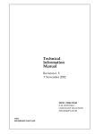
Technical Information Manual Revision n. 7 5 July 2011 MOD. N844/N844P/N845 8-16 CHANNEL LOW THRESHOLD DISCRIMINATOR NPO: 00103/00:844-5.MUTx/07 CAEN will repair or replace any product within the guarantee period if the Guarantor declares that the product is defective due to workmanship or materials and has not been caused by mishandling, negligence on behalf of the User, accident or any abnormal conditions or operations. CAEN declines all responsibility for damages or injuries caused by an improper use of the Modules due to negligence on behalf of the User. It is strongly recommended to read thoroughly the CAEN User's Manual before any kind of operation. CAEN reserves the right to change partially or entirely the contents of this Manual at any time and without giving any notice. Disposal of the Product The product must never be dumped in the Municipal Waste. Please check your local regulations for disposal of electronics products. MADE IN ITALY : We stress the fact that all the boards are made in Italy because in this globalized world, where getting the lowest possible price for products sometimes translates into poor pay and working conditions for the people who make them, at least you know that who made your board was reasonably paid and worked in a safe environment. (this obviously applies only to the boards marked "MADE IN ITALY", we can not attest to the manufacturing process of "third party" boards). Document type: User's Manual (MUT) Title: Mod. N844-N845 8-16 Channel Low Threshold Discriminator Revision date: 05/07/2011 Revision: 7 TABLE OF CONTENTS 1. 2. GENERAL DESCRIPTION.........................................................................................................................4 1.1. FUNCTIONAL DESCRIPTION .......................................................................................................................4 1.2. BLOCK DIAGRAM......................................................................................................................................5 TECHNICAL SPECIFICATIONS ..............................................................................................................6 2.1. PACKAGING ..............................................................................................................................................6 2.2. POWER REQUIREMENTS ............................................................................................................................6 2.3. FRONT AND BACK PANEL ..........................................................................................................................7 2.4. INPUT/OUTPUT CONNECTIONS ..................................................................................................................8 2.4.1. INPUT features................................................................................................................................8 2.4.2. OUTPUT features............................................................................................................................8 2.5. OTHER COMPONENTS ...............................................................................................................................9 2.5.1. Displays ...........................................................................................................................................9 2.5.2. Front panel switches........................................................................................................................9 2.5.3. Rotary handle ..................................................................................................................................9 2.6. 3. TECHNICAL SPECIFICATION TABLE .........................................................................................................10 OPERATING MODES ...............................................................................................................................11 3.1. POWER ON STATUS................................................................................................................................11 3.2. BACK PANEL SIGNALS ............................................................................................................................11 3.3. SETTING THE THRESHOLD AND DISABLING THE CHANNELS ....................................................................11 3.4. SETTING THE OUTPUT PULSE WIDTH .......................................................................................................12 LIST OF FIGURES FIG. 1.1: MOD. N845 BLOCK DIAGRAM (16 CHANNEL) ...........................................................................................5 FIG. 2.1: MOD. N845-N844 FRONT PANEL AND BACK PANEL ...................................................................................7 LIST OF TABLES TABLE 1.1: AVAILABLE ITEMS .................................................................................................................................4 TABLE 2.1: POWER REQUIREMENTS..........................................................................................................................6 TABLE 2.2: TECHNICAL SPECIFICATION TABLE .......................................................................................................10 NPO: 00103/00:844-5.MUTx/07 Filename: n844n845_rev7 Number of pages: 12 Page: 3 Document type: User's Manual (MUT) Title: Mod. N844-N845 8-16 Channel Low Threshold Discriminator Revision date: 05/07/2011 Revision: 7 1. General description 1.1. Functional description The CAEN Model N845 is a 16 CHANNEL LOW THRESHOLD DISCRIMINATOR housed in a single width NIM module. The module accepts 16 negative inputs and produces 16 NIM outputs + 16 /NIM outputs (complementary) on 48 front panel LEMO 00 connectors (NIM outputs are provided with a Fan-Out of two); a functional block diagram is shown in Fig. 1.1. A 8 Channel version, the CAEN Model N844, sharing the same functional features with the 16 Channel Model N845, is also available. The timing stage of the discriminator produces an output pulse whose width is adjustable in a range from 6 to 106 ns. The discriminator thresholds are individually settable in a range from -1 mV to -255 mV (1 mV step), via an 8-bit DAC. A 8 Channel positive input version (Model N844 P), with the thresholds settable in the 1 mV to 255 mV range, is also available. N844 boards can be converted into N844P (and N844P into N844 as well) by CAEN Personnel (module must be returned to CAEN); the Ordering Code of the customization is WN844POLEXCH. The back panel houses VETO and TEST inputs, the logical OR output (the relevant “OR” LED lights up if at least one channel is over threshold) and the Current Sum () output, which generates a current proportional to the input multiplicity, i.e. to the number of channels over threshold, at a rate of -1.0 mA per hit (-50 mV per hit into a 50 Ohm load) ± 20%. Table 1.1: Available items Code Item Description WN844POLEXCH N844 Polarity Exchange Polarity Exchange WN844PXAAAAA N844P 8 Ch Low Threshold Discriminator 50Ohm Positive Inputs WN844XAAAAAA N844 8 Ch Low Threshold Discriminator 50 Ohm Negative Inputs WN845XAAAAAA N845 16 Ch Low Threshold Discriminator 50 Ohm Negative Inputs NPO: 00103/00:844-5.MUTx/07 Filename: n844n845_rev7 Number of pages: 12 Page: 4 Document type: User's Manual (MUT) Title: Mod. N844-N845 8-16 Channel Low Threshold Discriminator Revision date: 05/07/2011 Revision: 7 1.2. Block diagram DACs, INHIBIT W LOGIC ........................ 8 bit 8 bit 8 bit 8 bit DAC W TH 0:7 DAC W TH 8:15 DAC DAC ch.0 ch.1 .................. 8 bit 8 bit DAC DAC ch14 ch.15 inhibit THRESHOLDS, W IDTH AND C.P.U. DEAD TIME INPUTS<0..15> discr. discr. ch.0 ch.1 ................. discr. ch.14 discr. ch.15 TEST OR LED VETO DISPLAY OUTPUTS<0..15> A, B OR OUT Fig. 1.1: Mod. N845 Block Diagram (16 Channel) NPO: 00103/00:844-5.MUTx/07 Filename: n844n845_rev7 Number of pages: 12 Page: 5 Document type: User's Manual (MUT) Title: Mod. N844-N845 8-16 Channel Low Threshold Discriminator Revision date: 05/07/2011 Revision: 7 2. Technical Specifications 2.1. Packaging The Model N844-N845 is housed in a 1U-wide NIM unit. 2.2. Power requirements The power requirements of the Mod. N844-N845 are as follows: Table 2.1: Power requirements Power Supply + 12 V - 12 V +6V - 6V NPO: 00103/00:844-5.MUTx/07 Filename: n844n845_rev7 N844/N844P N845 40 mA 30 mA 400 mA 1.85 A 60 mA 30 mA 800 mA 3.4 A Number of pages: 12 Page: 6 Document type: User's Manual (MUT) Title: Mod. N844-N845 8-16 Channel Low Threshold Discriminator Revision date: 05/07/2011 Revision: 7 2.3. Front and back panel Mod. N844 Mod. N845 16 CH LTD 8 CH LTD INPUT INPUT 0 1 2 3 4 5 6 7 8 9 12 10 13 14 0 1 2 3 4 5 6 7 11 15 OUTPUT 0 1 2 3 0 1 2 3 0 1 2 3 4 5 6 7 4 5 6 7 5 6 7 4 2 8 9 10 11 8 9 10 11 8 9 10 11 12 13 14 15 12 13 14 15 12 13 14 15 OUTPUT 0 1 0 1 2 3 2 3 4 5 4 5 6 7 6 7 OR THR THR WDT WDT SEL LCK T E S T O R OR SET V E T O SEL SET LCK Fig. 2.1: Mod. N845-N844 front panel and back panel NPO: 00103/00:844-5.MUTx/07 Filename: n844n845_rev7 Number of pages: 12 Page: 7 Document type: User's Manual (MUT) Title: Mod. N844-N845 8-16 Channel Low Threshold Discriminator Revision date: 05/07/2011 Revision: 7 2.4. Input/Output connections The location of the Mod. N844-N845 connectors is shown in Fig. 2.1. Their function and electromechanical specifications are listed in the following subsections and refer to the Mod. N845 (the Mod. N844 features specified between [ ]). 2.4.1. INPUT features INPUT CHANNELS: Mechanical specifications: 16 [8] LEMO 00 type connectors. Electrical specifications: Neg. polarity (pos. on N844 P), 50 Ohm impedance; DC coupling; maximum ratings: N844/N845: -0.4 V; (N844 P: 0.4 V); max. input frequency 60 MHz. Min. input: -3 mV (N844 and N845), +3 mV (N844 P). VETO INPUT: Mechanical specifications: 2 bridged LEMO 00 type connectors. Electrical specifications: standard NIM signal, high impedance, 15 ns minimum FWHM; leading edge of the VETO must precede of at least 12 ns the leading edge of the input and overlap completely the input signal; acts on all signals. TEST INPUT: Mechanical specifications: 2 bridged LEMO 00 type connectors. Electrical specifications: standard NIM signal, high impedance, 5 ns minimum FWHM, 70 MHz maximum input frequency. Test/Outptut delay: 10 ns. 2.4.2. OUTPUT features OUTPUT CHANNELS: Mechanical specifications: 48 [24] (32 [16] Fan-Out of two for OUT and 16 [8] single for /OUT) LEMO 00 connectors. Electrical specifications: NIM level on 50 Ohm impedance; pulse width adjustment from 6 ns to 106 ns; I/O delay: 9.5 ns. OR OUTPUT: Mechanical specifications: 2 LEMO 00 type connectors, Fan-Out of two. Electrical specifications: standard NIM signal, 50 impedance, 10 ns minimum FWHM, 50 MHz maximum frequency. OUTPUT: NPO: 00103/00:844-5.MUTx/07 Mechanical specifications: 2 bridged LEMO 00 type connectors. Electrical specifications: Filename: n844n845_rev7 Number of pages: 12 Page: 8 Document type: User's Manual (MUT) Title: Mod. N844-N845 8-16 Channel Low Threshold Discriminator Revision date: 05/07/2011 Revision: 7 current output (-1 mA 20% per hit), high impedance. 15 ns minimum FWHM, 30 MHz maximum frequency. 2.5. Other components 2.5.1. Displays The front panel hosts the following LEDs: INPUT Type: 16 [8] red LEDs Function: channel selected; they light up either when the channels are being programmed or when they are inhibited. OR Type: 1 green LED Function: it lights up if at least one output signal is present. 4 DIGIT DISPLAY Type: 4 digit red LED display Function: it indicates the channels’ status and programmed parameters’ values. 2.5.2. Front panel switches UPPER SWITCH Function: it allows to select the parameter which must be programmed. LOWER SWITCH Function: it allows to select the channel/block which must be programmed (SEL mode), and to “freeze” the programmed values (LCK mode). 2.5.3. Rotary handle Function: it allows to set the value of the parameter which is being programmed. NPO: 00103/00:844-5.MUTx/07 Filename: n844n845_rev7 Number of pages: 12 Page: 9 Document type: User's Manual (MUT) Title: Mod. N844-N845 8-16 Channel Low Threshold Discriminator Revision date: 05/07/2011 Revision: 7 2.6. Technical specification table Table 2.2: Technical specification table Features referred to Mod. N845 (Mod. N844/N844 P features specified between [ ] ) Packaging 1U-wide NIM unit Input channels Max. input voltage 16 [8] inputs (negative [N844:negative, N844 P:positive] polarity, 50 impedance, DC coupling) N844/N845 : -400 mV ; N844 P: +400 mV Min. detectable signal N844/N845 : -3 mV ; N844 P : +3 mV Max. input frequency 60 MHz Double pulse resolution 16 ns (8 ns output pulse width) Threshold range N844/N845: -1 mV to -255 mV (-1 mV step) N844 P: 1 mV to 255 mV (1 mV step) Output channels 32 [16] NIM (bridged) + 16 [8] /NIM (single) (50 ) Input/output delay Output width 10.5 1.5 ns Programmable from 6 ns to 106 ns Output rise/fall time Interchannel insulation OUT: 1.2 ns; /OUT: 2.5 ns 45 dB for 2.5 ns rise time input signals Control inputs NIM signals, high impedance: VETO: allows vetoing of all channels simultaneously TEST: triggers all the enabled channels at once Control outputs OR: standard NIM signal, 50 impedance; logic OR of outputs : current proportional to input multiplicity (-1 mA 20% per hit), high impedance INPUTS: 16 [8] red LEDs; they light up when the channel is being programmed or when it is inhibited 4-DIGIT DISPLAY: it indicates the channels’ status and programmed parameters’ values OR: green LED; it lights up if at least one output signal is present Displays NPO: 00103/00:844-5.MUTx/07 Filename: n844n845_rev7 Number of pages: 12 Page: 10 Document type: User's Manual (MUT) Title: Mod. N844-N845 8-16 Channel Low Threshold Discriminator Revision date: 05/07/2011 Revision: 7 3. Operating Modes 3.1. Power ON Status At Power ON the values of all the module’s parameters are those programmed before the last turning off. If one parameter’s value is meaningless, the unit sets it at half of its range. 3.2. Back panel signals Some operations can be performed via two external NIM signals: TEST: an input signal sent through this connector triggers all the enabled channels at once. This feature allows a complete test of the module without removing any input cable as well as it allows generation of a pattern of pulses suitable to test any following electronics. VETO: an input signal sent through this connector allows vetoing of all channels simultaneously. A veto pulse of width T will veto the input during this time T. Its leading edge must precede the output leading edge by at least 12 ns and overlap completely the input signal. VETO does not affect the TEST signal. Each one of these high impedance inputs is provided via two bridged connectors (placed on the board’s back panel) for daisy chaining. Note that since these are high impedance inputs, the chain has thus to be terminated on 50 on the last module; the same is needed whenever one module only is used, whose inputs have thus to be properly matched Moreover the back panel houses a Current Sum () output (on two bridged connectors) which generates a current proportional to the input signal multiplicity, i.e. to the number of channels over threshold, at a rate of -1.0 mA per hit (-50 mV per hit into a 50 load) ±20%. An OR output (with a Fan-Out of two) provides the logical OR of the output channels. 3.3. Setting the threshold and disabling the channels For each channel of the N844-N845 the discriminator threshold is set up via an 8 bit DAC. The threshold values can be programmed in a range from -1 mV to -255 mV with -1 mV steps (N844P: 1 mV to 255 mV with 1 mV steps). In order to set the threshold the Upper Switch (see § 2.5.2) must be placed on the THR position and the Lower Switch removed from the LCK position, then the channel that must be programmed is selected pulling up repeatedly the Lower Switch (the selected channel’s Led lights up). Note that after the last channel, by pulling up the lower switch, the Leds ligth up all together and, at this point, the threshold setting is performed over all the channels (this value must be confirmed by placing the Lower Switch on the LCK position, otherwise it is ignored). The NPO: 00103/00:844-5.MUTx/07 Filename: n844n845_rev7 Number of pages: 12 Page: 11 Document type: User's Manual (MUT) Title: Mod. N844-N845 8-16 Channel Low Threshold Discriminator Revision date: 05/07/2011 Revision: 7 threshold value is set via the front panel Rotary handle (see § 2.5.3) and shown on the 4-Digit Display: 1 leads to a –1mV and 255 to a –255 mV threshold value (reversed values for the N844 P); the step which follows 255 is four “*” appearing on the display (the relevant channel is inhibited), then again 0, 1, 2 etc; inhibited channels’ Leds are always lit when the lower switch is in lock (LCK) position. Once all the channels’ thresholds have been set to the desired value the Lower Switch must be placed on the LCK (lower) position and the word LOCK appears on the display. 3.4. Setting the output pulse width The output pulse width is adjustable on 8 bit from 6 to 106 ns and the chosen value is applied to a group of 8 channels each. The Mod. N845 has two groups (Ch. 0, 1, 4, 5, 8, 9, 12, 13 and Ch. 2, 3, 6, 7, 10, 11, 14, 15, respectively), the Mod. N844 has only one group. The Upper Switch must be placed on the WDT position and the Lower Switch removed from the LCK position, then the group is selected pulling up repeatedly the Lower Switch (the selected group’s Leds light up all together). The width’s value is set via the Rotary Handle and shown on the display (0 leads to a 6 ns and 255 to a 106 ns width with a non-linear relation for intermediate values); the step which follows 255 is again 0, then 1, 2 etc. Once the Pulse Widths have been programmed the Lower Switch must be placed on the LCK position and the word LOCK appears on the display. NPO: 00103/00:844-5.MUTx/07 Filename: n844n845_rev7 Number of pages: 12 Page: 12