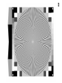
1
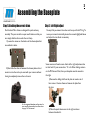
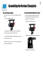
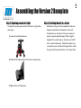
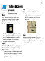
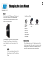
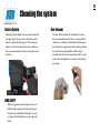
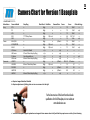
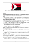
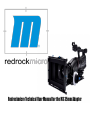
Redrockmicro Technical User Manual for the M3 35mm Adapter
Welcome!
Congratulations on your purchase of the M3 Cinema Lens Adapter!
Redrock Microsystems is committed to providing low cost, high quality cinema accessories to the independent
filmmaker.
This manual describes basic setup procedures and maintenance for your M3 system. We also have a set of
online video tutorials at start.redrockmicro.com that illustrate setup and configuration as well. We encourage
you to visit start.redrockmicro.com and view the video tutorials and access other resources to ensure your
Redrock equipment is set up properly and delivers optimal performance.
Visit http://start.redrockmicro.com to take advantage of setup tutorials, customer support forums, and a
number of other support resources
Redrock Microsystems, LLC
P.O Box: 271395
Flower Mound, TX 75027-1395
Redrock contact information
• Sales: [email protected]
• Support: [email protected]
• Order status: [email protected]
1
Table of Contents
1. M3 Features
Page 1. Features List
2. Assembling the unit
Page 3. Assembling the baseplate
Page 4. Assembling the baseplate
Page 6. Attaching the Camera
3. Set Up and Use
Page 7. What Lenses Should I
Choose?
Page 8. Setting back focus
Page 9. Power Information
4. Additional setup and Maintenance
Page 10. Changing the lens mount
Page 11. Collimating the Adapter
Page 12. Cleaning the Adapter
5.. Additional Documentation
Page 13. Camera Chart
Page 14. Warrantee Information
Page 15. Focus Chart
2
M3 Features List
M3 Features:
• Less than 1/2 stop light loss - best efficiency in industry, and superior color contrast when stopping down
• One step attachment to camera with breach-lock mount
• Completely reformulated optics eliminates distortion and vignetting
• Faster, easy setup
• New Uni-body design
• Collimating lens mount (new adapters come pre-collimated from the factory and adjustment is not necessary)
• Universal camera support, including Sony EX series cameras
• Interchangeable lens mounts without opening the adapter, including PL mount
• New, more powerful motor for silent operation, faster shutter speeds up to 1/500 and beyond
• Internal dust trap
• Easy access port for cleaning adapter’s internals
• Rechargeable battery system for 18+ hours of continuous level power
• Integrated battery charger: external sources power the adapter and charge internal batteries
• Works with external battery bricks such as V-mount and Anton Bauer
• Battery indicator status for charging, on, and low battery
• Legendary Redrock Bokeh from cinescreen II with cineLux
• Intelligent power (Internal Power Regulation, built-in battery charger, power management and fault protection, diagnostic status indicator)
• Shock mounted motor to reduce vibrations and to protect the motor and cinescreen
• Full rubber gaskets in all seals for silent operation and light leak prevention
• Works with existing Redrock microSupport system, Baseplate and microRods
• Aircraft-grade machined aluminum construction
• 100% glue-free assembly
Assembly
Assembling the Baseplate
Assembling the V.2 Baseplate
Attaching the Camera
Attaching the PL ring
Attaching the M3 to Camera
3
Assembling the Baseplate
Step 1. Attaching the correct shims
Our Redrock Micro shims are designed for quick and easy
assembly. They are cut with an open mouth feature so that you
can simply slide the shims under the rod clamp.
1) Loosen the screws on the bottom of the cheese plate that
are outlined in white.
2) Next slide the shims in between the cheese plate and rod
mount to raise the rods up to meet with your camera without
having to completely remove the rod mount.
Step 2. Left-Right adjust
You may find you camera’s lens does not line up with the M3 rig. To
move your camera horizontally, loosen the screws highlighted below
and adjust the riser block as necessary
Some cameras will need a more drastic left or right adjustment due
to their build. If your camera has a “d” in it’s Other Settings column
on the M3 Camera Chart, than your baseplate must be moved to
the right.
1) Remove the sliding sled from the plate to reveal a set of
four screws. Unscrew these and remove the plate from
the riser.
For the suggested baseplate configuration for
your camera, please review the camera chart
on page 13 of this manual.
2) Move the quick release over to the right as shown
below and reattach it.
4
Assembling the Version 2 Baseplate
Step 1. Attaching the camera
To attach your camera to the Version 2 baseplate follow these
steps:
1) Loosen circled thumbscrew:
Step 2. Adjusting the height of the camera
The Version 2 Baseplate is designed to allow you to
both raise and lower the camera so that you can
quickly achieve the correct height
1) Loosen the circled thumbscrew:
2) Completely remove the riser section, that includes the
camera plate and the two attached vertical rods.
3) Use a flathead screwdriver to tightly attach the screw into
the bottom of your camera.
2) Adjust the height of the camera as appropriate
4) Once the camera is secured on the riser, slide the rods back
into the top of the baseplate.
3) Tighten down the thumbscrew.
5
Assembling the Version 2 Baseplate
Step 3. Adjusting camera left-right
To adjust the cameras position either further left or right follow
these steps:
1) Loosen the circled thumbscrew:
2) Adjust the left-right position of the camera as appropriate
3) Tighten down the thumbscrew.
Step 4. Attaching the unit to a tripod
A difference that you will notice between the Version 1
baseplate and the Version 2 baseplate is the lack of
threaded holes on the bottom. This was necessary to
keep it's compact adjustable design. When using the
baseplate V2, use the threads on the bottom of the M3
unit to create a balanced rig. Many 35mm adapter rigs
can easily become front heavy, this design feature centers
the rig and reduces potential stress on the tripod head.
6
Attaching the Camera
Step 1. Attaching the PL Ring
The PL ring that is provided with the M3 is built with a 72mm
diameter. To attach the PL ring to a camera that is not built with
a 72mm diameter lens you'll need to attach a step ring between
the camera and the PL ring. Consult the camera chart to see if a
step up ring is necessary.
2) Choose the appropriate screw for your camera and remove
all the others.
3) Attach the base plate to your camera making sure the gold
locating pin is pointed forward. Once you have attached the
baseplate to your camera, you must make sure the baseplate is
in the unlocked position via the thumbscrew, than slide the
camera into place from the back.
Step 3. Putting it all together
1) Unscrew the PL breach-lock on the M3 until it is almost
completely unthreaded.
Step 2. Attaching the Camera to the V.1 baseplate
Our baseplate comes complete with a Bogen© manufactured quick
release base. This means that it uses the standard Bogen Rapid
Connect Sliding Plate. To attach your camera to the quick release base
you will:
1) Pull the quick release plate off of the base by loosening it. To
release the plate you must first loosen the thumbscrew on the
left side of the unit by rotating it counter clockwise. You will
than hold the button on the right side of the base as you
simultaneously pull out the plate.
2) Slide the camera into the adapter and tighten down the
breach-lock on the adapter. Also, be sure to lock down the
Bogen sliding plate on the baseplate.
Set Up and Use
What Lens Should I Use?
Setting Back Focus
Battery Information
7
Lens Choice
Things to watch for:
Aperture
f/1:X.X
Focal Length
XXmm
Auto-Focus
VS
Manual-Focus
Zoom
VS
Prime
A low maximum aperture means better low light performance and often
higher quality glasswork. It is also important to acquire lenses that have
manual aperture control as opposed to digital contacts that only allow it
to be controlled by a camera. The only exception to this is the Canon
EF mount. With the Redrock LiveLens controller mount, you can control
these lenses' apertures even though they are digital.
Depending on what purpose you intend the lens for, know whether it's a
wide or telephoto lens. Wide lenses are considered anything below
50mm, such as 28mm and 21mm, and telephoto lenses are known as
anything above 85mm for example 135mm and 200mm.
On all 35mm Adapter systems, focus will need to be pulled manually. This
makes auto-focus lenses unnecessary. Not only are they unnecessary, but
they often have a more "plastic" feel to them and can be more difficult to pull
focus on as opposed to their manual focus counter parts.
A zoom lens is a lens that covers a range of focal lengths, such as a
24mm-70mm or 70mm-200mm. While a prime lens is a lens that only covers
a single focal length, such as a 50mm or 35mm. While both these lenses have
their benefits, prime lenses often have a lower maximum aperture.
8
Setting Backfocus
BEFORE YOU START:
Step 1.
Turn off autofocus, auto iris, and
image stabilization before following
the below procedure.
Turn on your camera and zoom all the way out. Make sure
you are pointed at something bright such as a window or a
light. Also, make sure your M3 motor is OFF and the
ground glass is not rotating.
You will see something like the image above, do not worry
if your image is not centered, the M3 system is designed
with larger then necessary optics and it is not necessary
to for the image to be clear of the adapters interiors
simultaneously when performing step 2.
Step 2.
Attach a lens to the M3 and stop down the aperture of your
35mm lens. Then rotate the focus ring to the closest distance
marker on the barrel.
Zoom into the image until all sides of your image are clear of
any adapter interiors, or you have reached the recommended
setting for your camera from the camera setup chart at
start.redrockmicro.com.
Step 3.
Once zoomed in properly, focus on the texture of the
groundglass.
Tip: Use your camera’s focus assist or magnification to
help you get optimal focus, as well as your camera’s
peaking filter
Step 4.
Use the provided Focus Stop strap to keep the focus ring on
your camera from being altered once you completed this setup.
You will not need to adjust your camera’s zoom or focus once
your backfocus has been set.
9
Power Information
The battery door of the M3 is now conveniently located on the right side of the unit for easy access when the batteries need to be
changed, as shown below. The M3 uses an intelligent power system and rechargeable NiMH AA batteries. Fully charged batteries last
for about 18 hours. Normally when the unit is on, the LED indicator pulses off and on. The unit will begin blinking when you have 20
minutes of power remaining. Any AA NiMH rechargeable batteries will work in the system. We ship the M3 with two 2000mAh
batteries.
The M3 has an additional two auxiliary ports
located above the power button. These are
available for both loop through power and later
expansion.
LED Pattern
State
Description
Solid
On
Unit is running normally.
1 blink
On
The batteries are low and about 20 minutes of power remain.
Fade in/out
Charging
M2e is charging. !When M2e is recharged, LED will turn off.
3 blinks
On or
Charging
M2e has shut off due to components overheating. !Unplug unit and confirm voltage
going to unit is 9V-18V. !If problem persists contact [email protected].
4 blinks
Charging
M2e is preparing new batteries and a new charge cycle needs to be run. !Unplug
and plug in power to the unit to continue charge. !NEVER do this more than once.
5 blinks
On or
Charging
Batteries are missing or dead. !If unit is new or replacing batteries does not change
message, contact [email protected].
10
Changing the Lens Mount
Step 1:
On the front of the M3 flange you will find two sets
of set screws. One set of three will be located
closest to the unit, and than another set of three
farther out, as shown below.
Available Lens Mount:
Pentax S
Nikon
Pentax K
Canon EF Live
Lens
PL Cinema
Canon EF
Canon FD
Olympus OM
Minolta MD
The set farthest out is used to change lens mounts.
Unscrew all three of them, and remove the lens
mount. Replace the current lens mount with the
new one.
NOTE:
The PL mount replaces the entire front
threaded section of the M3 collimating
flange.
Optional Step:
After changing a lens mount, it is highly recommended to
collimate your adapter with a new lens to assure your lens
markings match up. To learn how to collimate your new
lens mount, review the next section of this manual.
11
Collimating the lens mount
WHAT AND WHY DO I NEED TO COLLIMATE
When you collimate the M3, you adjust the Flange
Focal Length – the distance between the cinescreen
and the rear element of your 35mm lens. All M3
units are collimated at the factory, though there are
some situations where you would want to collimate
the unit:
-When changing lens mounts-all lens types have a
different FFL.
-When your lens markings do not match up to
actual focus distances or you are unable to reach
infinity focus.
BEFORE YOU START
To collimate the M3 you’ll need a focus chart. We
include a focus chart in every M3 manual on Page
13, so if you do not already own one, feel free to
use the one included in this manual.
Step 1:
Attach the chart to a stand or wall and make sure it is evenly
lit.
Step 2:
Place the camera on a tripod and make sure the film plane line
of the adapter is exactly 3 feet away from the focus chart.
Properly set your backfocus and turn on your M3 system.
Step 3:
Loosen the three set screws on the collimating flange closest
to the M3 body.
Step 4:
Use the widest lens you have available, as wider lenses are
more sensitive to flange focal length. Open the aperture of the
35mm lens all the way and set the focus ring on your 35mm
lens to 3 feet.
Step 5:
Twist the collimating ring until the focus chart is as sharp as
possible.
Note: Using an external monitor with a
magnification filter assures the most
accurate collimation.
Step 6:
Tighten the 3 set screws on the flange as in Step 3.
12
Cleaning the system
Interior System
Cleaning a 35mm adapter has never been easier. On
the right side of the unit next to the battery door
there is a skinny tall cleaning port. To remove any
specks or dust in the adapter, open the small door
and use pressurized air to blow out any obstructive
particles.
LENS SAFETY
When using compressed air, always be sure to
hold the bottle upright at all times and spray it
once off to the side before allowing it to come
in contact with the adapter port, same goes for
lenses.
Rear Element
To clean off the backside of the adapter first use a
form of pressurized air, be it from a compressed air
container or a blower as shown below. Next spray a
lens cloth with a single spray of lens cleaning solution
and clean the rear element. Be careful if using a
reusable cloth, as if there are particles of dirt or dust
on the cloth already, there is a chance of scratching
your optics.
13
Camera Chart for Version 1 Baseplate
!"#$%"&'()
!"#$
I1#"#
O1#1N"#)C
*"+()",!-.(/
%&'
%2
6-'
783
G82
8(;J-AK8L3//A8L3/2
8(;((L;!=M)=N
(K;!=M)=N
L!;!=M)=N
(6;!=M)=N
(O8-&/
(68://
?68-//
(0I-2/
(0IE/
0'(1,23#4
#
#
#
&&9&:;!<=>;?"@#
#
#
#
#
61M)=N;O=M;0"P=Q
3&HHR&:HH;!<=>;'>;S)#*
G"#9<+M=1P=P;T=#N
E3HHR&:HH;!<=>;'>;S)#*
#
B:HH9&:HH;!<=>;?"@#
#
#
E3HHR&:HH;!<=>;'>;S)#*
235(),6/-&7 2-.,083+
*"+()",083+ 9--+
:-&$5
;'8(),0(''3#45
()*+
#
#
&,
-./0
1
()*+
#
#
&3
.,0
145
()*+
#
#
&2
-./0
1
()*+
-AB;)#C+
#
DE
/.,F-./
1
()*+
#
#
&2
-./H
145
()*+
#
-AB)#C+
&3
-./0
1
()*+
-AB;)#C+
#
F:2
-./0
1
()*+
-AB;)#C+
#
&.,;0
145
#A1
#
#A1
#
#
C
#A1
#
#A1
#
#
C
#A1
#
#A1
#
#
#A1
#A1
#
#A1
#
#
C
()*+
#
-AB)#C+
:293-., .,&H=<=MN
1
()*+
-AB;)#C+
#
&2
3&
1
()*+
#
-AB)#C+
B2
EB
1
()*+
#
-AB)#C+
B,
3E
1
#A1
#
#A1
#
#
C
!"#$%&'()%*#+,!-%#./!0!1(2%)#3(*!01%4
0"#$%&'()%*#!45'*/,%6/#78#*1(4(6-#91!/%#76#)(*%)#76%#*:)%;#*%/#/7#/<%#)(-</
For the latest version of this chart that also includes
specifications for the V2 Baseplate, visit our website at
start.redrockmicro.com
:"#=<%#:'))%6/#0!*%91!/%#*'997)/#*>*/%,#47%*#67/#*'997)/#/<%*%#:!,%)!*#4'%#/7#/<%#8!:/#/<!/#/<%>#)%&'()%#7?%)#!6#(6:<#78#)(*%)#*<(,,(6-
14
Warranty Information
WARRANTY
Redrock Microsystems LLC (REDROCK MICRO) warrants that its accessories, when installed in accordance with REDROCK MICRO
installation instructions, will perform in accordance with the REDROCK MICRO specifications current as of the date of shipment,
and will be free from defects in material and workmanship for a period of one (1) month on new accessories as defined below and
thirty (30) days on repaired accessories and/or components. Specifically excluded from this Warranty is any physical damage caused
by abuse, accident, or improper operation, and any lack of performance attributable to such abuse, accident, or improper operation,
as determined by REDROCK MICRO. REDROCK MICRO shall not be liable for any incidental or consequential damages, including loss
of production time or money, regardless whether the accessory functioned properly or improperly for any reason, including those for
which REDROCK MICRO bears liability under this Warranty. The one (1) month warranty period for new accessories shall be the one
(1) month period beginning with the date of the accessories receipt by the customer, except that in no instance shall the warranty
period extend beyond three (3) months from the date of shipment as established with the serial number as identified on the
accessory, its date of manufacture and its date of shipment. Where an accessory consists of multiple components, the warranty
period for all the components shall commence on the receiptdate of the last component, providing that such date shall be no later
than sixty (60) days from the earliest date of shipment of a component for the purchased accessory. For repaired or replaced
accessories, the repaired or replaced component is warranted to be free of material and workmanship defects, and to perform its
function in accord with REDROCK MICRO specifications for a period of thirty (30) days from its date of shipment, or its original new
accessory Warranty period, whichever is the latter. All claims under this Warranty shall be immediately submitted to REDROCK
MICRO in writing and are subject to confirmation by REDROCK MICRO. Should REDROCK MICRO deem it appropriate to return the
accessory or a component thereof to an REDROCK MICRO-designated location, it will issue the Buyer a Return Material
Authorization (RMA), which must accompany all returns. The returned accessory or component thereof shall remain the property of
the Buyer who shall ship it freight prepaid to the designated REDROCK MICRO location with the RMA number clearly displayed on
the packaging exterior and all accompanying paperwork. REDROCK MICRO, upon receipt and subsequent confirmation of a
Warranty defect, at its sole option, shall repair or replace the accessory or its component and return it freight prepaid to the Buyer
within thirty (30) days from date of its receipt. On otherequipment such as a video camera and/or other peripheral equipment, its
original manufacturer warrants such equipment separately, and warranty claims should be addressed to that respective
manufacturer. This Warranty is made in lieu of all other warranties whatsoever, express, implied and statutory, including, without
limitation, the implied warranties of merchantability and fitness. The acceptance of any order with REDROCK MICRO is expressly
made subject to the Buyer’s agreement to this Warranty.
15