1
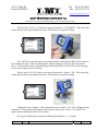
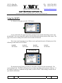
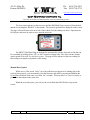
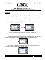
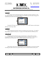
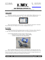
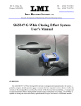
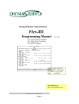
101 N. Alloy Dr. Fenton, MI 48430 Ph (810) 714-5811 Fax (810) 714-5711 [email protected] Research, Development and Manufacturing of Precision Measuring Systems SK5475 Half Shaft User’s Manual OVERVIEW: The LMI SK5475 Half Shaft Measurement Gage is designed and manufactured to be used as a portable, compact, durable, and precision electronic linear measurement instrument that delivers deviation measurements from a set nominal reference point of 7.33mm of the half shaft assembly. Any and all “Good” readings are then automatically sent to the AIS Box for data collection purpose. 101 N. Alloy Dr. Fenton, MI 48430 Ph (810) 714-5811 Fax (810) 714-5711 [email protected] Research, Development and Manufacturing of Precision Measuring Systems Warranty Information In the USA, this unit is warranted by LMI against defects in materials and workmanship for 1 year from date of original purchase. If you transfer ownership, the warranty is automatically transferred to the new owner and remains in effect for the original 1 year period. During the warranty period we will repair, or at our option, replace at no charge, product that proves to be defective, provided it is returned, shipping prepaid to LMI. This warranty does not apply if the product has been damaged by accident or misuse or as a result of service or modification by other than LMI, or by hardware, software, interfacing or peripherals not provided by LMI. Please retain this document for your records. No other express warranty is given. The repair or replacement of a product is your exclusive remedy. Any implied warranty of merchantability or fitness is limited to the 1 year duration of this written warranty. Some States do not allow the exclusion or limitations of incidental or consequential damages, so the above exclusion or limitations may not apply to you. LMI Customer Service LMI Customer Service can be reached at (810) 714-5811 Monday through Friday between 8:00 a.m. and 5:00 p.m. Eastern Standard Time. Call LMI Customer Service to: Place orders Return LMI equipment for service Inquire about the status of an order or repair Form: CA 175 12/07/12 R:\Quality\Calibration Instructions\CA 175 SK5475 Half Shaft Manual.doc Rev: A Page 2 of 14 101 N. Alloy Dr. Fenton, MI 48430 Ph (810) 714-5811 Fax (810) 714-5711 [email protected] Research, Development and Manufacturing of Precision Measuring Systems Returns for Service Contact Customer Service for a Return Material Authorization (RMA) number. Include a detailed description of the problem. Pack the equipment properly. Use the original shipping container, if possible. LMI cannot assume responsibility for damage caused by improper packaging. Send the equipment to the following address: LMI Corporation Attn: Repair Department 101 N. Alloy Drive Fenton, MI 48430 LMI Technical Support LMI Technical Support experts are only a phone call away. Contact Technical Support at 810-714-5811 Monday through Friday between 8:00 a.m. and 5:00 p.m. Eastern Standard Time for the following reasons: To assist in setup and configuring LMI equipment To help implement data collection applications To troubleshoot LMI equipment You and also reach LMI Technical Support by Email at [email protected]. You can email your questions anytime. Please include your name, phone number, and a detailed description of the problem. LMI On-Site Training LMI Technical Support provides on-site training for all LMI products. Contact LMI Support Services at 810-714-5811 for pricing & scheduling information. Schedule a day at your facility or at LMI in Fenton, Michigan. LMI Website Please visit us on the web at www.lmicorporation.com for more information. Form: CA 175 12/07/12 R:\Quality\Calibration Instructions\CA 175 SK5475 Half Shaft Manual.doc Rev: A Page 3 of 14 101 N. Alloy Dr. Fenton, MI 48430 Ph (810) 714-5811 Fax (810) 714-5711 [email protected] Research, Development and Manufacturing of Precision Measuring Systems Gage Overview Contact Tip verifies half shaft position UP, PB, DOWN BUTTONS Battery Icon Shows level of battery charge Moves through Routine, menu screen, and accepts changes in menu UP PB Hub Contact Base DOWN SCREEN Displays Test Routine, Readings, Mode, etc. Charging Port Status LED Will Blink RED or GREEN depending on test result Measuring Half Shaft using the SK5475 Half Shaft Gage: Gage Tip makes contact with end of Half Shaft Display shows, Pass/Fail and which reading is next Form: CA 175 12/07/12 Gage Base pilots shoulder of Hub These 2 buttons must make contact with hub in order for a reading to be taken and sent. If they do not make contact, the display will read “No Contact”. R:\Quality\Calibration Instructions\CA 175 SK5475 Half Shaft Manual.doc Rev: A Page 4 of 14 101 N. Alloy Dr. Fenton, MI 48430 Ph (810) 714-5811 Fax (810) 714-5711 [email protected] Research, Development and Manufacturing of Precision Measuring Systems Getting started “Wake up” the gage by pressing the “PB” button (center round button) on display. If the SK5457 half shaft gage is not associated with the base being used, continue with the steps below, otherwise skip down to “Using the SK5457” section on page 8. Note: Once an SK5475 Gage is Associated to a Base Station, these steps are not necessary. Update Mode Enter the “Update Mode” by pressing and holding the “PB” button down 15 seconds until a menu appears on the screen. Using the Arrow buttons, move the cursor down to “Update Mode” and press the “PB” button. Selecting this mode starts the green LED flashing. This mode is only used to associate a gage with a base, as well as reference the firmware version number. Press and hold the PB for 15 seconds to exit this mode. Form: CA 175 12/07/12 R:\Quality\Calibration Instructions\CA 175 SK5475 Half Shaft Manual.doc Rev: A Page 5 of 14 101 N. Alloy Dr. Fenton, MI 48430 Ph (810) 714-5811 Fax (810) 714-5711 [email protected] Research, Development and Manufacturing of Precision Measuring Systems Association to a Base While in the update mode press the reset button on the back of your base unit. The Green, Yellow, and Red LEDs will flash on for 15 seconds. At this time press and release the PB button on the gage to associate the tester to the base. If the gage associated with the base correctly, you will see between 1 and 3 Green LED’s (depends on signal strength) on the base station flash on then off. Auto Shutdown If a half shaft is not measured and a reading sent to the AIS Box for a period of 5 minutes, the unit will go into a low power mode and the screen will go blank, to conserve battery power. To “Wake up” the gage, press the PB button. Form: CA 175 12/07/12 R:\Quality\Calibration Instructions\CA 175 SK5475 Half Shaft Manual.doc Rev: A Page 6 of 14 101 N. Alloy Dr. Fenton, MI 48430 Ph (810) 714-5811 Fax (810) 714-5711 [email protected] Research, Development and Manufacturing of Precision Measuring Systems Calibration Calibration is done from the factory, and is not necessary, but if the user wishes to calibrate: Enter the “Calibration” by pressing and holding the “PB” button down 4-5 seconds until a menu appears on the screen. Using the Arrow buttons, move the cursor down to “Calibrate” and press the “PB” button. Using the SK5476 Master Block, place the gage onto the block to calibrate “LO”, verify the tip is fully extended, and press the “PB” button to accept this reading: NO CONTACT means the tester is not making contact with the Master Block. When it does a live reading will appear. Push the PB to calibrate low. Form: CA 175 12/07/12 R:\Quality\Calibration Instructions\CA 175 SK5475 Half Shaft Manual.doc Rev: A Page 7 of 14 101 N. Alloy Dr. Fenton, MI 48430 Ph (810) 714-5811 Fax (810) 714-5711 [email protected] Research, Development and Manufacturing of Precision Measuring Systems When a good “CAL LO” is done, the screen will advance to “Cal High-PB”. Fully retract the contact tip with your finger and then press the “PB” Button to accept this reading. NO CONTACT means the gage is not making contact with the Master Block. When it does a live reading will appear. This can easily happen when pressing up on the tip while in the master block. User must be careful to not lift the gage off the master block, which will lose allow the gage to lose contact and not record a reading. When a good “CAL HI” is done, the screen will advance to “Master – PB”. Fully retract the contact tip with your finger and then press the “PB” Button to accept this reading. Calibration is now complete. If the calibration was successful a “CAL OK” will appear and a reading of 7.33mm (nominal) will appear at the bottom of the screen. If not a “CAL BAD” will appear and the calibration will have to be redone. Exit a good calibration by pressing and holding the PB button 2 – 3 seconds. Form: CA 175 12/07/12 R:\Quality\Calibration Instructions\CA 175 SK5475 Half Shaft Manual.doc Rev: A Page 8 of 14 101 N. Alloy Dr. Fenton, MI 48430 Ph (810) 714-5811 Fax (810) 714-5711 [email protected] Research, Development and Manufacturing of Precision Measuring Systems Using the SK5475 To “Wake Up” the gage, press the “PB” Button. A test is initiated by the gage being firmly positioned onto the hub and making contact with the half shaft. The circuit senses the contact to the steel hub and reads the position of the sensor. The gage will not send a reading if all contacts are not made with the hub. This is the normal operating screen. When a test is performed the unit will display one of the following on the bottom two LCD lines: PASSDS XX.XXmm FAILDS XX.XXmm PASSPS XX.XXmm FAILPS XX.XXmm DS = Driver Side PS = Passenger Side The displayed string (Passxx or Failxx) is sent to the wireless base unit automatically. The actual reading is not. The LED will Display Green or Red, depending on the outcome of the test. If the reading is equal to or within the set spec limits, it will be Green. If the reading is outside the set spec limits it will be Red. Form: CA 175 12/07/12 R:\Quality\Calibration Instructions\CA 175 SK5475 Half Shaft Manual.doc Rev: A Page 9 of 14 101 N. Alloy Dr. Fenton, MI 48430 Ph (810) 714-5811 Fax (810) 714-5711 [email protected] Research, Development and Manufacturing of Precision Measuring Systems The user can not advance to the next test, until the Half Shaft Gage is removed from the hub, and the screen displays “READY” at the bottom. The test to be performed is displayed on the screen. The gage will not advance to the next side of the vehicle if a bad reading was taken. Operator must fix bad part, and retest in order to move onto the next side. The SK5475 Half Shaft Gage is defaulted to automatically advance from side to side but can be overridden by holding in the “UP” or “DN” buttons to change sides. The Auto Advance feature can be turned off as well. See the Menu section. The gage will not advance to the next reading if a bad reading was sampled, regardless of this setting. Manual Reset Option While in use, if the screen “locks” up or the radio does not appear to be sending data to the wireless base properly, you can manually reset the firmware and radio by pressing and holding the Up and Down buttons at the same exact time, for 3 seconds. This may take 2 or 3 tries as you try to press down the buttons at the same time. When the reset takes place, you will see the screen flash the LMI Wireless Logo on the screen. Form: CA 175 12/07/12 R:\Quality\Calibration Instructions\CA 175 SK5475 Half Shaft Manual.doc Rev: A Page 10 of 14 101 N. Alloy Dr. Fenton, MI 48430 Ph (810) 714-5811 Fax (810) 714-5711 [email protected] Research, Development and Manufacturing of Precision Measuring Systems MENU Pushing and holding in the “PB” button for 15 seconds, will display the Menu Screen: The UP and DN buttons will move the arrow to the various selections and press the Center Button (PB) to select any option in the menu. Adjust DWL/BBL The Dwell (DWL) is the time allowed to determine whether or not a reading is stable, during a test. The Bobble “BBL” is the allowed movement between consecutive readings when the test is underway, which tells the gage when the plunger has stopped moving and a reading can be taken. After a reading is taken, the gage must move past this threshold in order to change sides and begin another test. This option eliminates the chance of sending more than one response to the AIS Box for a given test. Form: CA 175 12/07/12 R:\Quality\Calibration Instructions\CA 175 SK5475 Half Shaft Manual.doc Rev: A Page 11 of 14 101 N. Alloy Dr. Fenton, MI 48430 Ph (810) 714-5811 Fax (810) 714-5711 [email protected] Research, Development and Manufacturing of Precision Measuring Systems Limits/Delays The upper and lower limits are the spec limits determined by the user, and recognized by the gage as to what is a good reading and what is a bad reading. The LED response as well as the output to the AIS Box will depend on these settings. The Default Limits are: Lower Limit is set to – 5.23 and the Upper Limit is set to – 9.25 Any readings greater than or equal to the Lower Limit, and less than or equal to the upper limit will present a “Pass” result part and the LED will blink Green. Anything outside these limits will present a “Fail” result and the LED will blink Red. Pressing the UP or DN buttons will adjust the test limits by .01mm per press. ADJ Test Delay This setting will adjust the length of time it takes the gage to send a reading, after it has made electrical contact with the HUB and the reading has stabilized. The Default delay is set to 7. Pressing the UP or DN buttons will change the test delay by 1 second per press. Press the “PB” button to exit this option and return to the testing window. Form: CA 175 12/07/12 R:\Quality\Calibration Instructions\CA 175 SK5475 Half Shaft Manual.doc Rev: A Page 12 of 14 101 N. Alloy Dr. Fenton, MI 48430 Ph (810) 714-5811 Fax (810) 714-5711 [email protected] Research, Development and Manufacturing of Precision Measuring Systems Set Start Side Some routines will start on the Passenger Door, while others will start on the Driver’s door. This option will allow you to select which routine you would like to start with, and so the gage will automatically start at the correct position each time. Pressing the UP button will change the start routine. Press the “PB” button to exit this option and return to the testing window. CALIBRATE Allows calibration of the SK5475 when user/company policy feels necessary. The SK5476 Master Block is required for this process. See pages 7 & 8 of this manual for calibration process. AUTO ADV OFF This option will either allow the gage to automatically move between Diver side and Passenger Side readings, once a previous reading has been taken, if turned ON. If this option is turned off, the user must press the “UP” or “Down” buttons to advance to the next test. When testing, and no matter which option this is set to, holding the up or down arrow buttons will change what side is done next to go back to the previous test and re-do that test if they wish. Form: CA 175 12/07/12 R:\Quality\Calibration Instructions\CA 175 SK5475 Half Shaft Manual.doc Rev: A Page 13 of 14 101 N. Alloy Dr. Fenton, MI 48430 Ph (810) 714-5811 Fax (810) 714-5711 [email protected] Research, Development and Manufacturing of Precision Measuring Systems UPDATE MODE This option is needed to associate the SK5475 with a MobileColllect USB Base Station. See page 5 of this manual for information on this. When in this mode, the LED will blink Green. This screen will also show you the firmware version and date/time of the build. To Exit this menu, hold down the “PB” Button, for 15 seconds, as displayed on the screen. BATTERY For maximum battery life keep charged whenever possible. The battery will say charged for 4 -5 days under normal operating conditions, but this is very dependent upon overall use. Use the supplied LMI Wireless Gauge Charger to charge the gage. - A RED LED on the Charger indicates a charging Battery - A GREEN LED indicates a fully charged battery. Note: The SK5475 Hub Gage does not have an On/Off button. The gage will go into a low power “sleep” mode after 5 minutes of no activity, but will continue to draw a minimal current. Due to this low current draw, gages not used for a period of time or not left on a charger when not in use, will draw the battery down & require a full charge before being used. Form: CA 175 12/07/12 R:\Quality\Calibration Instructions\CA 175 SK5475 Half Shaft Manual.doc Rev: A Page 14 of 14