1
1.375 - 2.000 in.
Split Shot Cutters®
1.0 Assembly of Split Shot Cutters - except SSC-2000-311,
SSC-2000-321 and SSC-2000-341
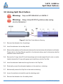
Figure 1: Split Shot Cutter Assembly with Trough - Exploded View
1.1
Unpack the hardware and explosive Segments. The Segments will be numbered in sequential
order for assembly.
1.2 Remove the Screw (item #6) securing the Housing (item #1) to the Bottom Sub (item #2).
Remove the Bottom Sub and attached assembly from Housing.
1.3
Remove the Cap Screw (item #9) and Washer (item #10) from the detonator Sub (item #4).
Note: Skip this step if you are using the 48” system as these parts are
not present.
1.4
Remove the Screws (item #6) that secure the Charge Trough (item #3) to the Bottom Sub.
1.5
Remove the O-rings (item #7) from their package and visually inspect them for cuts or cracks.
Lightly lubricate the O-rings with grease and install them onto the Bottom Sub (item #2).
1.6
Re-install the Charge Trough onto the Bottom Sub and secure it in place with the screws.
4 I MAN-REC-SSC (R09)
©2007, 2015 Owen Oil Tools All rights reserved