1
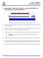
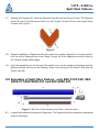
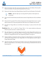
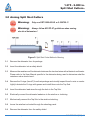
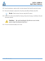
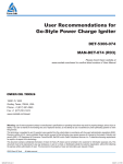
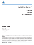
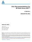
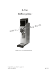
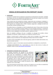
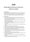
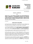
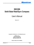
Split Shot Cutters®
1.375 inch
2.000 inch
MAN-REC-SSC (R09)
12001 Cr 1000
Godley, Texas, 76044, USA
Phone: +1 (817) 551-0540
Fax: +1 (817) 551-1674
www.corelab.com/owen
Warning: use of owen equipment contrary to manufacturer’s specifications or operating instructions may result in property damage, serious injury or
fatality. If you are not trained in the handling and use of explosive devices, do not attempt to use or assemble any owen perforating systems or owen
firing devices.
This technology is regulated by and, if exported, was exported from the united states in accordance with the export administration regulations (EAR).
Diversion contrary to U.S. Law is prohibited. Export and/or re-export of this technology may require issuance of a license by the bureau of industry and
security (BIS), U.S. Department of Commerce. Consult the BIS, the EAR, and/or Owen Compliance Services, Inc. To determine licensing requirements
for export or re-export of this technology.
This document contains confidential information of Owen Oil Tools LP (Owen) and is furnished to the customer for information purposes only. This
document must not be reproduced in any way whatsoever, in part or in whole, or distributed outside the customer organization, without first obtaining
the express written authorization of owen. This document is the property of owen and returnable upon request of Owen.
©2007, 2015 Owen Oil Tools
All rights reserved
1.375 - 2.000 in.
Split Shot Cutters®
Description:
Owen’s Split Shot® Cutter was designed for use where traditional jet cutters were not effective
or could not be used. The Split Shot® Cutter is run in a linear configuration adjacent to any collar
or connection and positioned by inline magnets. After detonation the collar or connection is split
allowing the pipe to be freed for easy removal.
Benefits / Capabilities:
• “Air shippable” at Class 1.4S
• Conforms to API RP-67
• Can be run through heavy mud, paraffin, collapsed tubing, and reduced restrictions.
• Can be run 4X faster than conventional jet cutters.
• Must be run decentralized to maximize effectiveness of tool.
• If shooting in a connection with a premium thread, (i.e. VAM, Hydril, etc.), please contact your
local Owen representative for recommendations.
Patents:
United States Patent 5,720,344: Method of longitudinally splitting a pipe coupling within a wellbore.
Specifications:
TOOL
Tool Diameter
1-3/8 IN.
1-3/8 in.
34.9 mm
2 IN.
1.375 in.
Housing Material
34.9 mm
2.000 in.
50.8 mm
2.000 in.
Explosive Length
18, 24, 48 in.
18, 24, 48 in.
45.7, 70.0 cm
45.7, 70.0 cm
45.7, 70.0, 122.0 cm
Explosive Load
Minimum Running
Restriction
Recommended
Tubing / Casing
Applications
50.8 mm
Aluminum
600 grain/ft
1.775 in.
45.1 mm
900 grain/ft
1.775 in.
45.1 mm
1200 grain/ft
2.625 in.
66.7 mm
2000 grain/ft
2.625 in.
66.7 mm
2.375 to 2.875 in.
2.875 to 4.500 in.
3.500 to 7.000 in.
5.500 to 16.000 in.
60.3 to 73.0 mm
73.0 to 114.3 mm
88.9 to 177.8 mm
139.7 to 406.4 mm
Maximum Pressure
psi
MPa
psi
MPa
psi
MPa
psi
MPa
up to 200°F (93°C)
14,000
96.5
14,000
96.5
11,700
80.7
11,700
80.7
13,250
91.4
13,250
91.4
11,000
75.8
11,000
75.8
11,800
81.4
11,800
81.4
9,850
67.9
9,850
67.9
200°F to 325°F
(93°C to 163°C)
325°F to 400°F
(163°C to 200°C)
Pressure Ratings are based on 1 hour exposure. For durations exceeding 1 hour please contact Owen
Engineering. Refer to the “Time vs Temperature Chart for Explosives” for allowable operating temperatures.
2 I MAN-REC-SSC (R09)
©2007, 2015 Owen Oil Tools All rights reserved
1.375 - 2.000 in.
Split Shot Cutters®
ITEM
1
DESCRIPTION
MAGNETIC TOP SUB
1 3/8” OD (600gr/ft)
SSC-1375-005
1 3/8” OD (900gr/ft)
SSC-1375-005
2” OD (1200gr/ft)
SSC-2000-010
2” OD (2000gr/ft)
SSC-2000-010
D
C
C
C
48” LONG ASSY
DETONATOR
18” LONG ASSY
24” LONG ASSY
DET-3050-009LS
SSC-1375-311
SSC-1375-321
or 2-300750-1
(3 - 6” Segments)
(4 - 6” Segments)
--
DET-3050-009LS
SSC-1375-312
SSC-1375-322
SSC-1375-342
or 2-300750-1
(6 - 3” Segments)
(8 - 3” Segments)
(16-3” Segments)
DET-3050-009LS
SSC-2000-312
SSC-2000-322
SSC-2000-342
or 2-300750-1
(6 - 3” Segments)
(8 - 3” Segments)
(16 - 3” Segments)
DET-3050-009LS
SSC-2000-311
SSC-2000-321
SSC-2000-341
or 2-300750-1
(9 - 2” Segments)
(12 - 2” Segments)
(24 - 2” Segments)
• Top Sub and Detonator must be ordered separately from Split Shot® Assembly.
• Magnetic Top Sub may be used more than once.
• HMX Split Shots are available by special order. Parts should be ordered by replacing the
3 with a 4, ie. SSC-XXXX-4XX
NOTE: Split Shots can be run using Safe Detonator System or Owen Green DET™ as
a replacement to the DET-3050-009LS. Please Reference Safe Ignition Systems
Section.
WARNING
Use of Owen equipment contrary to manufacturer’s
specifications may result in property damage, serious
injury or fatality. If you are not trained in the handling and
use of explosive devices, do not attempt to assemble any
Owen Perforating Systems or Owen Firing Devices.
For Technical Assistance, Please Contact:
Owen Oil Tools
12001 County Road 1000
Godley, TX. 76044
Tel: (817) 551-0540 Fax: (817) 551-0795
http://www.corelab.com/owen
©2007, 2015 Owen Oil Tools All rights reserved
MAN-REC-SSC (R09) I 3
1.375 - 2.000 in.
Split Shot Cutters®
1.0 Assembly of Split Shot Cutters - except SSC-2000-311,
SSC-2000-321 and SSC-2000-341
Figure 1: Split Shot Cutter Assembly with Trough - Exploded View
1.1
Unpack the hardware and explosive Segments. The Segments will be numbered in sequential
order for assembly.
1.2 Remove the Screw (item #6) securing the Housing (item #1) to the Bottom Sub (item #2).
Remove the Bottom Sub and attached assembly from Housing.
1.3
Remove the Cap Screw (item #9) and Washer (item #10) from the detonator Sub (item #4).
Note: Skip this step if you are using the 48” system as these parts are
not present.
1.4
Remove the Screws (item #6) that secure the Charge Trough (item #3) to the Bottom Sub.
1.5
Remove the O-rings (item #7) from their package and visually inspect them for cuts or cracks.
Lightly lubricate the O-rings with grease and install them onto the Bottom Sub (item #2).
1.6
Re-install the Charge Trough onto the Bottom Sub and secure it in place with the screws.
4 I MAN-REC-SSC (R09)
©2007, 2015 Owen Oil Tools All rights reserved
1.375 - 2.000 in.
Split Shot Cutters®
1.7
Starting with Segment #1, install the Segment (item #5) into the Charge Trough. The Segment
should fit next to the Spring and down into the Charge Trough with the inner angle facing
outward, see Figure 2.
Figure 2
1.8
Repeat installation of Segments with the consecutive number Segment in a linear direction
until the all the Segments are in the Charge Trough. All of the Segments should fit tightly in
the Charge Trough without gaps.
1.9
Insert the assembly into the Housing. Be careful to line up the explosive Segments with the
different colored window on the Housing. Secure the Housing to the Bottom Sub with the
Screw (item #6).
2.0 Assembly of Split Shot Cutters - only SSC-1375-322, SSC2000-311,SSC-2000-321 and SSC-2000-341
Figure 3: Split Shot Cutter Assembly with Rails - Exploded View.
2.1
Unpack the hardware and explosive Segments. The Segments will be numbered in sequential
order for assembly.
©2007, 2015 Owen Oil Tools All rights reserved
MAN-REC-SSC (R09) I 5
1.375 - 2.000 in.
Split Shot Cutters®
2.2
Remove the Screw (item #6) securing the Housing (item #1) to the Bottom Sub (item #2).
Remove the Bottom Sub and attached assembly from Housing.
2.3
Remove the Cap Screw (item #9) and Washer (item #10) from the Detonator Sub (item #4).
Note: Skip this step if you are using the 48” system as these parts are
not present.
2.4
Remove the Flat Head Screws (item #8) that secure the Charge Rails (item #3) to the Bottom
Sub.
2.5
Remove the O-rings (item #7) from their package and visually inspect them for cuts or cracks.
Lightly lubricate the O-rings with grease and install them onto the Bottom Sub (item #2).
2.6 Re-install the Charge Rails onto the Bottom Sub securing it in place with the Flat Head
Screws.
Caution: Make sure to install the Charge Rails in the same orientation as they were
before they were removed or a misfire could result!
2.7 Start with Segment #1; install the Segment (item #5) into the Charge Rails with the inner
angle first until it contacts the internal step. The Segment should fit next to the Spring and
between the Charge Rails with the inner angle facing outward, see Figure 4.
2.8
Repeat installation of Segments with the consecutive number Segment in a linear direction
until the all the Segments are in the Charge Rails. All of the Segments should fit tightly in
Charge Rails without gaps.
2.9
Insert the assembly into the Housing. Be careful to line up the explosive Segments with the
different colored window on the Housing. Secure the Housing to the Bottom Sub with the
Screw (item #6).
Figure 4
6 I MAN-REC-SSC (R09)
©2007, 2015 Owen Oil Tools All rights reserved
1.375 - 2.000 in.
Split Shot Cutters®
3.0 Arming Split Shot Cutters
Warning: Only use DET-3050-009LS or 2-300750-1!
Warning: Always follow API RP-67 guidelines when arming
electrical detonators!
Figure 5: Split Shot Cutter Method of Arming
3.1
Remove the detonator from its package.
3.2
Insert the detonator into a safety shield.
3.3
Measure the resistance of the detonator between the two lead wires with a blaster’s multimeter.
Please refer to the User Manual specific to the detonator being used to determine what the
resistance value should read..
3.4
Remove the O-rings (item #7) from their package and visually inspect them for cuts or cracks.
Lightly lubricate the O-rings with grease and install them onto the Top Sub.
3.5
Insert the detonator lead wires through the hole in the Top Sub.
3.6
Electrically connect the detonator leadwires to the wireline or toolstring.
3.7
Mechanically connect the Top Sub to the wireline toolstring.
3.8
Insure the wireline is shunted through the shooting panel.
3.9 Remove the detonator from the safety shield.
©2007, 2015 Owen Oil Tools All rights reserved
MAN-REC-SSC (R09) I 7
1.375 - 2.000 in.
Split Shot Cutters®
3.10 Insert the detonator, output end first, into the detonator Sub (item #4) inside the Housing.
3.11 Secure the detonator in place with a Cap Screw (item #9) and Washer (item #10).
Note: Skip this step if you are using the 48” system.
3.12 Insert the Top Sub into the Split Shot Housing. Secure the Housing to the Bottom Sub with
the Screw (item #6).
Caution:
Be careful installing the Top Sub so as not to chafe,
pinch or break the detonator lead wires!
3.13 The tool is armed and ready to run in hole.
8 I MAN-REC-SSC (R09)
©2007, 2015 Owen Oil Tools All rights reserved