1
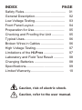
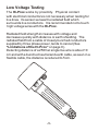
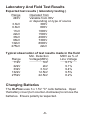
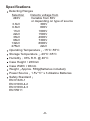
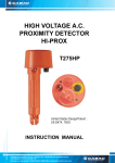
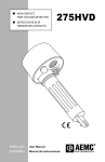
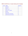
HIGH VOLTAGE A.C.
PROXIMITY DETECTOR
HI-PROX
T175HP
6.
6k
V
k
11
0V
24
3.3kV
Te
st
V
22kV
V
6 6k
kV
275
132kV
V
United States Design Patent : US D474, 705 S
33k
OFF
INDEX
PAGE
Safety Rules.............................................
General Description.................................
Low Voltage Testing.................................
Front Panel Layout..................................
Preparation for Use.................................
Checking and Proofing the Unit .............
Typical Uses...........................................
Broken Wires in Cables .........................
High Voltage Testing...............................
Limitations of the Hi-Prox ......................
Laboratory and Field Test Result ...........
Changing Batteries ................................
Specifications.........................................
Limited Warranty.....................................
01
02
03
04
05
05
06
06
07
07
08
08
09
10
Caution, risk of electric shock.
Caution, refer to the user manual.
Safety Rules
The Hi-Prox has been designed with safety in mind.
However, no design can completely protect against
incorrect use.
Electrical circuits are dangerous and lethal through
lack of caution or poor safety practice. The following
rules should reduce the danger:
Read the user manual carefully and completely before
using the tester. Fully understand the instructions before
using this product. Follow the instructions for every test.
Take all the necessary precautions. Do not exceed the
limits of this instrument.
The Hi-Prox must never be in physical contact
with any conductor higher than 1kV. This is a proximity
detector, not a detector which works by contact.
Always use a fiber glass rod or any authorized stick.
A high voltage test is carried out with the tester attached to
an operating stick, sometimes called "links stick".
Verify the rotary switch setting before measuring. Make
sure it is on the correct setting for your application.
Always check that the Hi-Prox is working before
and after the test.
Do not touch any exposed wiring, connections, or other
"live" parts of an electrical circuit.
This instrument should only be used by a competent,
suitably trained person who understands this test
procedure fully. Personnel working with high voltage
should be trained regularly.
-1-
General Description
The Hi-Prox consists of an internal pickup sensor
plate, a rotary switch as sensitivity selector, a sound
annunciator (high pitch, high power buzzer), a visual
indicator (high bright LEDs), and three "C" size batteries.
The Hi-Prox detects AC voltages using the sensor
plate. The sensor plate collects part of the radiated electric
field (V/M). The electric field is seen by the internal circuitry
and triggers the input of a CMOS integrated circuit. The
integrated circuit charges a capacitor via a diode. Once that
capacitor reaches a certain level, the buzzer and LEDs
annunciator are turned "ON".
The trigger level is fixed (CMOS logical level change). The
"self-test" inserts a voltage on the sensor plate, just like if the
sensor would pick up a voltage. The Hi-Prox allows
identification of AC voltages from 220Vac to 275kVac. The
enclosure is made out of industrial grade polyurethane. The
enclosure can be attached to a link stick. The small cylinder
part of the Hi-Prox fits into most link stick adaptors.
-2-
Low Voltage Testing
The Hi-Prox works by proximity. Physical contact
with electrical conductors is not necessary when testing for
live lines. Its sensor senses the radiated field which
surrounds live conductors. It is recommended not to touch
high voltage wires with the Hi-Prox.
Radiated field strength increases with voltage and
decreases quickly with distance or earth shielding. The
radiated field from a cable of closely bunched conductors
supplied by three phase power, tends to cancel (See
"Limitations of the Hi-Prox" on page 9 ).
Detecting distance of a 250Vac single live wire is about 10
cm and with a bunched neutral and earth cable, as seen in a
flexible cable, the distance is reduced to 5 cm.
-3-
Front Panel Layout
OFF
Self-Test
240Vac
3.3kV
6.6kV
11kV
22kV
33kV
66kV
132kV
275kV
Buzzer
LEDs
Battery Holder
- Turn the pick-up sensor off
- Check if the entire circuitry is working
- 240Vac selection
- 3.3kVac selection
- 6.6kVac selection
- 11kVac selection
- 22kVac selection
- 33kVac selection
- 66kVac selection
- 132kVac selection
- 275kVac selection
- High noise level buzzer
- High bright low current LEDs
Buzzer
Rotary Selector
LEDs
V
k
11
0V
6.
6k
24
3.3kV
V
22kV
V
66 k
kV
2 75
-4-
132kV
V
Battery Holder
3 3k
Te
st
OFF
Preparation for Use
When unpacked, the tester should be inspected for any
visible signs of damage, and the preliminary checks
described in the user manual should be performed to ensure
that it is operating correctly. If there is any sign of damage,
or if the instrument does not operate correctly, return it to
your nearest supplier.
This instrument is powered by three "C" type batteries.
Checking And Proofing The Tester
Switch the sensitivity to "SELF-TEST". The buzzer of the
Hi-Prox should beep and the LEDs should light.
This indicates that the Hi-Prox is operational.
Verify the working of this unit by selecting 240Vac and place
the dome against a low voltage live conductor or rub the
dome with a cloth or against an item of clothing as this
generates a static DC which triggers the detection of circuit.
The light and beeper should go "on" as if a live wire is being
approached.
6.
6k
V
V
t
k
11
0V
22kV
OFF
V
66k
132kV
275
kV
V
-5-
33k
Te
s
3.3kV
24
Approaching the dome near a
computer screen or a TV screen
(not liquid crystal display type)
should also trigger the tester
while on the 240V selection.
Typical Uses
Identify and check live cables
Check and detect live high voltage cables (using
extension hot stick)
Find fault in flexible cables
Check earth equipment
Service neon lighting
Trace live wires
Check high frequency radiation
Detect residual or induced voltages
Broken Wires In Cables
Faults in damaged flexible cables are found by applying
low voltage to each conductor. Earthing the remainder
(the wires that do not need to be traced. Do not earth the
live wire, so that they can be detected by the Hi-Prox.)
and moving the tester along the cable until the change in
condition is obtained. (Flexible cables, as used in mining
and building industries, are readily repairable when the
break in the cable is located).
-6-
High Voltage Testing
The rotary switch (attenuator) is used to identify and
differentiate various HV live cables. The tester must be
used in conjunction with a long and insulating rod when
measuring high voltage (kV).
Non-Contact
It is advised that the tester should never come into contact
with cables (kV) as this tester is merely a non-contact AC
Proximity tester.
Limitations On The Hi-Prox
It is recommended that this tester is not used in HV
yards of mixed voltages. In the presence of mixed
voltages, the tester can become unreliable.
Problems can arise when the tertiary circuit
of a 275/133/11kV transformer is tested. The
electric field of the HV and MV bus bars can
trigger the detector when it is about 3m above
the ground. This is common with most of the
electric field voltage detectors. Users should
be aware of it. The tester can pick up
adjacent circuit to the one being tested and
Indicates the wrong information to the user.
-7-
Laboratory And Field Test Results
Expected test results ( laboratory testing )
Range
Operated from
240V
Variable from 80V
or depending on type of source
3.3kV
300V
6.6kV
800V
11kV
1000V
22kV
1500V
33kV
4000V
66kV
7300V
132kV
8000V
275kV
22kV
Typical observation of test results made in the field
Min. Detection
MDV as % of
Range
Voltage(MDV)
Line Voltage
11kV
1kV
9.1%
22kV
2kV
9.1%
33kV
3.1kV
9.4%
132kV
12.5kV
9.5%
275kV
22.5kV
8.2%
Changing Batteries
The Hi-Prox uses 3 x 1.5V "C" cells batteries. Open
the battery cover (turn counter-clockwise) to remove the
batteries. Ensure polarity is respected.
-8-
Specifications
Detecting Ranges
Selection
Detects voltage from
240V
Variable from 80V
or depending on type of source
3.3kV
300V
6.6kV
800V
11kV
1000V
22kV
1500V
33kV
4000V
66kV
7300V
132kV
8000V
275kV
22kV
Operating Temperature -15°C~55°C
Storage Temperature -20°C~65°C
Humidity 93% R.H. @ 40°C
Case Height 260mm
Case Width 96mm
Weight Approx. 550g(Batteries included)
Power Source 1.5V "C" x 3 Alkaline Batteries
Safety Standard
EN 61326-1
EN 61000-4-2
EN 61000-4-3
EN 55011
-9-
Limited Warranty
We warrant the product to be free from defective materials or
factory workmanship. We agree to repair or replace this product
with no charge for parts and service, if used under normal
operation and is a result of manufacturer defects. If we are unable
to repair or replace this product, we will make a full refund of the
purchase price. Consult the user manual for proper instruction
regarding use of this instrument. Our obligation under this
warranty is limited to repairing, replacing or making refund of this
test equipment which proves to be defective within 36 months from
the date of purchase.
This warranty does not apply to any of our products which have
been repaired or altered by unauthorized persons in any way. In
our sole judgement, if the stability or reliability of products are
injured, or which have been subject to misuse, abuse,
misapplication, negligence or accident, or the serial numbers have
been altered, defaced or removed, this warranty will not apply.
All warranties implied by law are hereby limited to a period of 36
months, and the provisions of the warranty are expressed in lieu of
any other warranties expressed or implied.
The purchaser agrees to assume all liability for any damages or
bodily injury which may result from the use or misuse of the product
by the purchaser, or its user, his employees, or others, and the
remedies provided by this warranty are expressed in lieu of any
other liability we may have included in incidental or consequential
damages.
We reserve the right to discontinue models at any time, or change
specification, price or design, without notice and without incurring
any obligation.
-10-